CHEVROLET CORVETTE 2003 5.G Owners Manual
Manufacturer: CHEVROLET, Model Year: 2003, Model line: CORVETTE, Model: CHEVROLET CORVETTE 2003 5.GPages: 368, PDF Size: 2.55 MB
Page 311 of 368

Vehicle Identi®cation
Vehicle Identi®cation Number (VIN)
This is the legal identi®er for your vehicle. It appears on
a plate in the front corner of the instrument panel, on
the driver's side. You can see it if you look through the
windshield from outside your vehicle. The VIN also
appears on the Vehicle Certi®cation and Service Parts
labels and the certi®cates of title and registration.
Engine Identi®cation
The 8th character in your VIN is the engine code. This
code will help you identify your engine, speci®cations
and replacement parts.
Service Parts Identi®cation Label
You'll ®nd this label located inside the glovebox. It's
very helpful if you ever need to order parts. On this
label is:
·your VIN,
·the model designation,
·paint information and
·a list of all production options and special equipment
Be sure that this label is not removed from the
vehicle.
5-83
Page 312 of 368

Electrical System
Add-On Electrical Equipment
Notice:Don't add anything electrical to your
vehicle unless you check with your dealer ®rst.
Some electrical equipment can damage your vehicle
and the damage wouldn't be covered by your
warranty. Some add-on electrical equipment can
keep other components from working as they
should.
Your vehicle has an air bag system. Before attempting
to add anything electrical to your vehicle, see
Servicing Your Air Bag-Equipped Vehicle on page 1-47.
Accessory Power Plug
The accessory power plug can be used to connect
electrical equipment such as a cellular phone or
CB radio. It is located behind the carpeting, on the
passenger's side toe-board, at the top left corner near
the body control module. Be sure to follow the
installation instructions included with the equipment.To use the accessory power plug, do the following:
1. Remove the toe-board panel by pulling at the top of
each corner of the panel.
2. Locate the black connector at the top left corner of
the compartment near the body control module
above the two white diagnostic connectors.
3. Disconnect the connector pigtail by pulling forward
on the plastic locking tab and pull the connection
apart from the wire harness.
The plug has the following three separate wires:
·The orange wire connects to battery power.
·The yellow wire connects to ignition power. (Power
is only available when the ignition is in ON.)
·The black wire connects to ground.
5-84
Page 313 of 368

Notice:When using the accessory power plug:
·Do NOT splice wires directly into the vehicle
electrical wire harness. If done incorrectly,
spicing may cause damage to your electrical
system and would not be covered by the
vehicle's warranty.
·The maximum load of any electrical equipment
should not exceed 20 amps.
·Be sure to turn off any electrical equipment
when not in use. Leaving electrical equipment
on for extended periods of time can drain
your battery.
·DO NOT use this plug if the electrical equipment
requires frequent connecting and disconnecting.
This may cause excessive wear on the
accessory power plug and damage your
electrical system and the damage would not be
covered by your warranty.
Headlamp Wiring
The headlamp wiring is protected by a circuit breaker.
An electrical overload will cause the lamps to go on and
off, or in some cases to remain off. If this happens,
have your headlamp wiring checked right away.
Windshield Wiper Fuses
The windshield wiper motor is protected by a fuse and
an internal circuit breaker. If the motor overheats
due to heavy snow, etc., the wiper will stop until the
motor cools. If the overload is caused by some electrical
problem and not snow, etc., be sure to get it ®xed.
Power Windows and Other Power
Options
Circuit breakers protect the power seats and other
power accessories. When the current load is too heavy,
the circuit breaker opens and closes, protecting the
circuit until the problem is ®xed or goes away.
5-85
Page 314 of 368
Fuses and Circuit Breakers
The wiring circuits in your vehicle are protected from
short circuits by a combination of maxi-fuses, mini-fuses
and circuit breakers. This greatly reduces the chance
of ®res caused by electrical problems.
Look at the silver-colored band inside the fuse. If the
band is broken or melted, replace the fuse. Be sure you
replace a bad fuse with a new one of the identical
size and rating.
If you ever have a problem on the road and don't have
a spare fuse, you can borrow one that has the same
amperage. Just pick some feature of your vehicle
that you can get along without ± like the radio or
cigarette lighter ± and use its fuse, if it is the correct
amperage. Replace it as soon as you can.
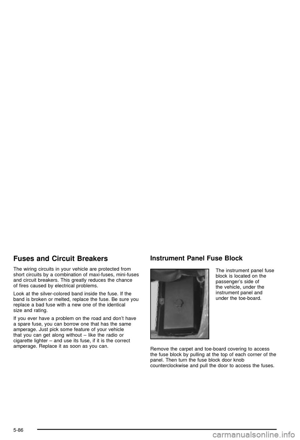
Instrument Panel Fuse Block
The instrument panel fuse
block is located on the
passenger's side of
the vehicle, under the
instrument panel and
under the toe-board.
Remove the carpet and toe-board covering to access
the fuse block by pulling at the top of each corner of the
panel. Then turn the fuse block door knob
counterclockwise and pull the door to access the fuses.
5-86
Page 315 of 368
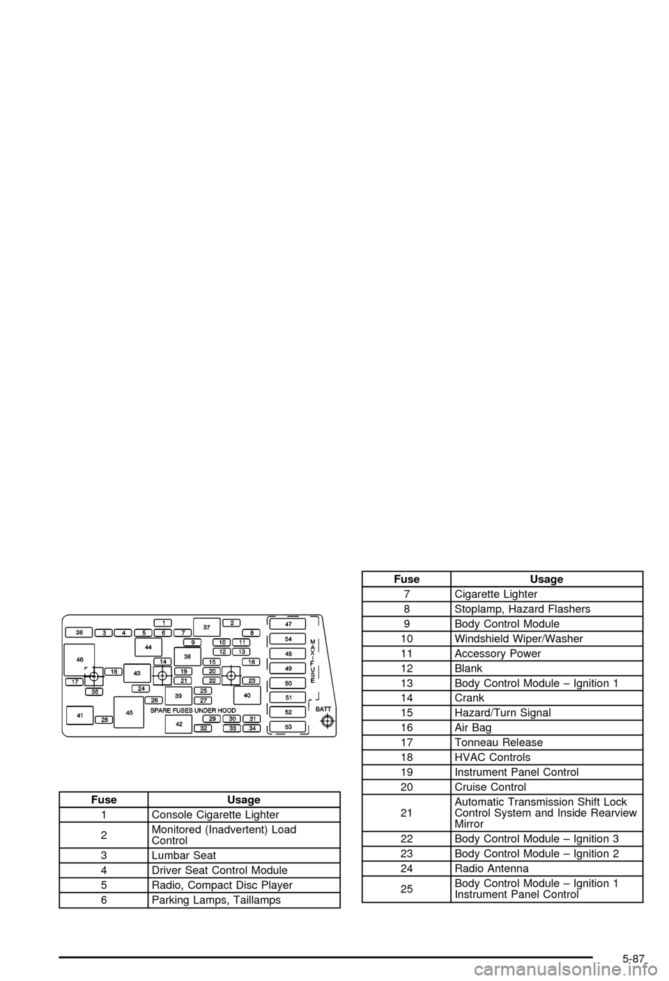
Fuse Usage
1 Console Cigarette Lighter
2Monitored (Inadvertent) Load
Control
3 Lumbar Seat
4 Driver Seat Control Module
5 Radio, Compact Disc Player
6 Parking Lamps, Taillamps
Fuse Usage
7 Cigarette Lighter
8 Stoplamp, Hazard Flashers
9 Body Control Module
10 Windshield Wiper/Washer
11 Accessory Power
12 Blank
13 Body Control Module ± Ignition 1
14 Crank
15 Hazard/Turn Signal
16 Air Bag
17 Tonneau Release
18 HVAC Controls
19 Instrument Panel Control
20 Cruise Control
21Automatic Transmission Shift Lock
Control System and Inside Rearview
Mirror
22 Body Control Module ± Ignition 3
23 Body Control Module ± Ignition 2
24 Radio Antenna
25Body Control Module ± Ignition 1
Instrument Panel Control
5-87
Page 316 of 368
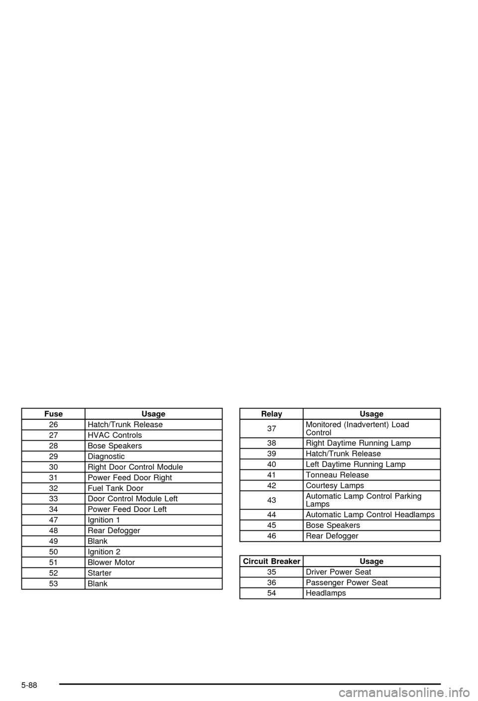
Fuse Usage
26 Hatch/Trunk Release
27 HVAC Controls
28 Bose Speakers
29 Diagnostic
30 Right Door Control Module
31 Power Feed Door Right
32 Fuel Tank Door
33 Door Control Module Left
34 Power Feed Door Left
47 Ignition 1
48 Rear Defogger
49 Blank
50 Ignition 2
51 Blower Motor
52 Starter
53 BlankRelay Usage
37Monitored (Inadvertent) Load
Control
38 Right Daytime Running Lamp
39 Hatch/Trunk Release
40 Left Daytime Running Lamp
41 Tonneau Release
42 Courtesy Lamps
43Automatic Lamp Control Parking
Lamps
44 Automatic Lamp Control Headlamps
45 Bose Speakers
46 Rear Defogger
Circuit Breaker Usage
35 Driver Power Seat
36 Passenger Power Seat
54 Headlamps
5-88
Page 317 of 368
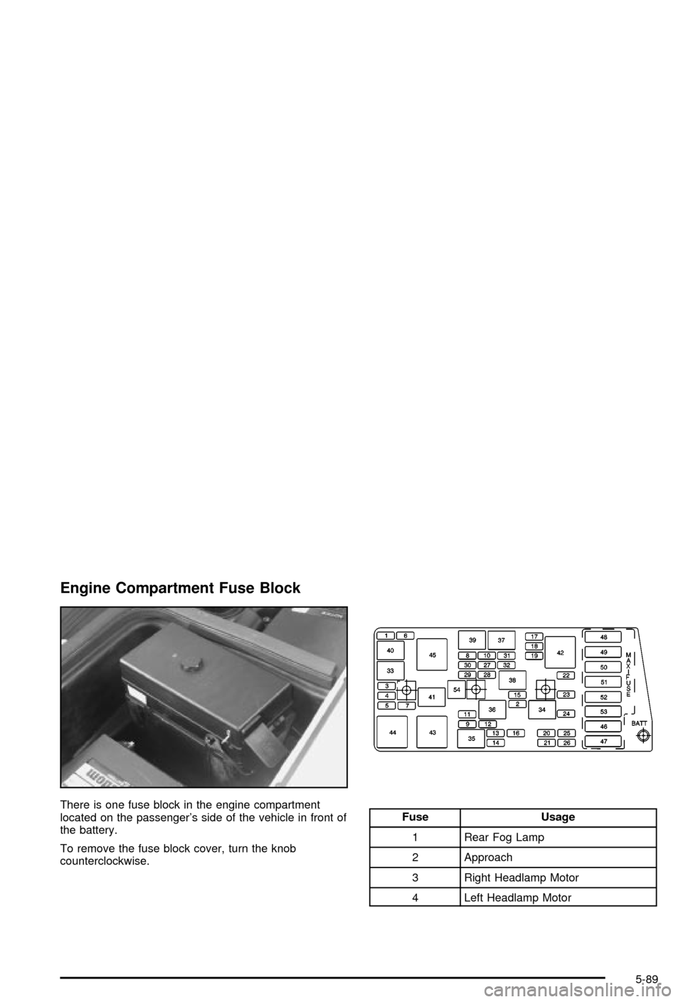
Engine Compartment Fuse Block
There is one fuse block in the engine compartment
located on the passenger's side of the vehicle in front of
the battery.
To remove the fuse block cover, turn the knob
counterclockwise.Fuse Usage
1 Rear Fog Lamp
2 Approach
3 Right Headlamp Motor
4 Left Headlamp Motor
5-89
Page 318 of 368
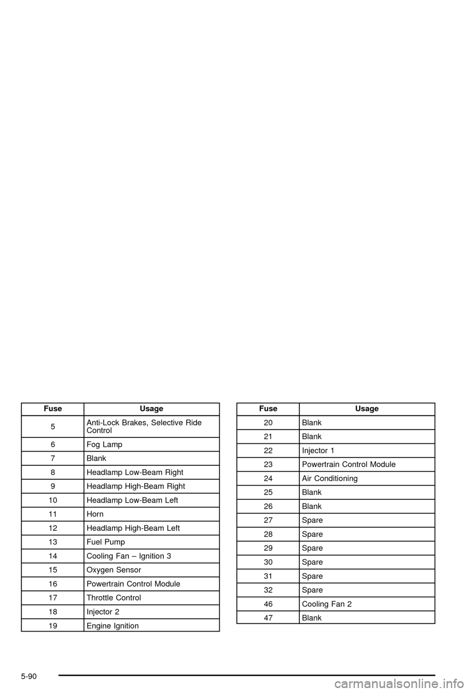
Fuse Usage
5Anti-Lock Brakes, Selective Ride
Control
6 Fog Lamp
7 Blank
8 Headlamp Low-Beam Right
9 Headlamp High-Beam Right
10 Headlamp Low-Beam Left
11 Horn
12 Headlamp High-Beam Left
13 Fuel Pump
14 Cooling Fan ± Ignition 3
15 Oxygen Sensor
16 Powertrain Control Module
17 Throttle Control
18 Injector 2
19 Engine IgnitionFuse Usage
20 Blank
21 Blank
22 Injector 1
23 Powertrain Control Module
24 Air Conditioning
25 Blank
26 Blank
27 Spare
28 Spare
29 Spare
30 Spare
31 Spare
32 Spare
46 Cooling Fan 2
47 Blank
5-90
Page 319 of 368
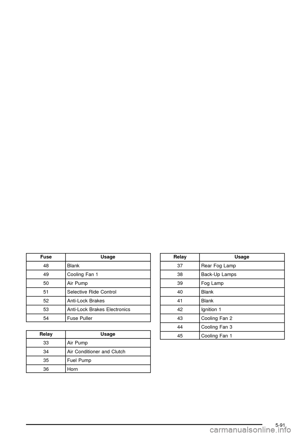
Fuse Usage
48 Blank
49 Cooling Fan 1
50 Air Pump
51 Selective Ride Control
52 Anti-Lock Brakes
53 Anti-Lock Brakes Electronics
54 Fuse Puller
Relay Usage
33 Air Pump
34 Air Conditioner and Clutch
35 Fuel Pump
36 Horn
Relay Usage
37 Rear Fog Lamp
38 Back-Up Lamps
39 Fog Lamp
40 Blank
41 Blank
42 Ignition 1
43 Cooling Fan 2
44 Cooling Fan 3
45 Cooling Fan 1
5-91
Page 320 of 368
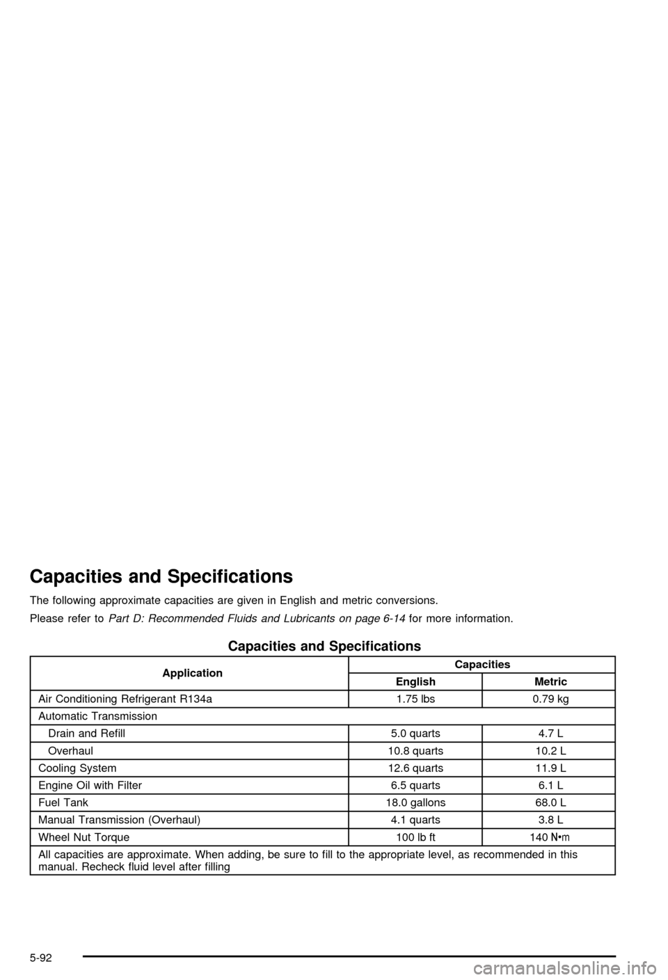
Capacities and Speci®cations
The following approximate capacities are given in English and metric conversions.
Please refer to
Part D: Recommended Fluids and Lubricants on page 6-14for more information.
Capacities and Speci®cations
ApplicationCapacities
English Metric
Air Conditioning Refrigerant R134a 1.75 lbs 0.79 kg
Automatic Transmission
Drain and Re®ll 5.0 quarts 4.7 L
Overhaul 10.8 quarts 10.2 L
Cooling System 12.6 quarts 11.9 L
Engine Oil with Filter 6.5 quarts 6.1 L
Fuel Tank 18.0 gallons 68.0 L
Manual Transmission (Overhaul) 4.1 quarts 3.8 L
Wheel Nut Torque 100 lb ft 140Y
All capacities are approximate. When adding, be sure to ®ll to the appropriate level, as recommended in this
manual. Recheck ¯uid level after ®lling
5-92