brake fluid CHEVROLET DYNASTY 1993 Service Manual
[x] Cancel search | Manufacturer: CHEVROLET, Model Year: 1993, Model line: DYNASTY, Model: CHEVROLET DYNASTY 1993Pages: 2438, PDF Size: 74.98 MB
Page 1288 of 2438
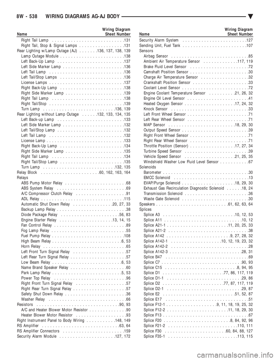
Wiring Diagram
Name Sheet Number
Right Tail Lamp .......................... .131
Right Tail, Stop & Signal Lamps .................131
Rear Lighting w/Lamp Outage (AJ) .......136, 137, 138, 139
Lamp Outage Module ....................... .138
Left Back-Up Lamp ........................ .137
Left Side Marker Lamp ...................... .136
Left Tail Lamp ........................... .136
Left Tail/Stop Lamps ....................... .136
License Lamps ........................... .137
Right Back-Up Lamp ....................... .138
Right Side Marker Lamp ..................... .139
Right Tail Lamp .......................... .138
Right Tail/Stop ........................... .139
Turn Lamp .......................... .136, 139
Rear Lighting without Lamp Outage ......132, 133, 134, 135
Left Back-up Lamp ........................ .133
Left Side Marker Lamp ...................... .132
Left Tail/Stop Lamp ........................ .132
Left Tail Lamp ........................... .132
License Lamp ............................ .133
Right Back-Up Lamp ....................... .134
Right Side Marker Lamp ..................... .135
Right Tail Lamp .......................... .134
Right Tail/Stop Lamp ....................... .135
Turn Lamp .......................... .132, 135
Relay Block ..................... .60, 162, 163, 164
Relays ABS Pump Motor Relay .......................68
ABS System Relay ..........................69
A/C Compressor Clutch Relay ...................91
ADL Relay .............................. .115
Automatic Shut Down Relay ...............20, 27, 33
Backup Lamp Relay ..........................38
Diode Package Relay ..................... .56, 83
Engine Starter Relay ................... .13, 14, 15
Fan Control Relay ...........................89
Fog Lamp Relay ............................55
Fuel Pump Relay .......................... .108
High Beam Relay ..........................6,53
Horn Relay ...............................65
Left Front Turn Signal Relay ....................57
Left Rear Turn Signal Relay .....................57
Low Beam Relay ..........................6,53
Name Brand Speaker Relay .....................60
Park Lamp Relay ..........................5,53
Power Top Relay ...........................96
Right Front Turn Signal Relay ...................57
Right Rear Turn Signal Relay ....................57
Safety Shut Down Relay .......................36
Washer Relay .............................66
Resistors .............................. .90, 93
A/C and Heater Blower Motor Resistor ..............90
Heater Blower Motor Resistor ...................93
Right Instrument Panel to Body Wiring ...........148, 149
RS Amplifier ............................ .63, 64
RS Amplifier Connectors ...................... .159
Security Alarm Module .................... .127, 172Wiring Diagram
Name Sheet Number
Security Alarm System ....................... .127
Sending Unit, Fuel Tank ....................... .107
Sensors Airbag Sensor .............................85
Ambient Air Temperature Sensor .............117, 119
Brake Fluid Level Sensor ......................72
Camshaft Position Sensor ......................30
Charge Air Temperature Sensor ..................32
Crankshaft Position Sensor .....................33
Coolant Level Sensor .........................72
Engine Coolant Temperature Sensor ..........21, 26, 32
Engine Oil Level Sensor .......................41
Heated Oxygen Sensor .................. .17, 24, 32
Knock Sensor .............................33
Left Front Wheel Sensor .......................71
Left Rear Wheel Sensor .......................71
MAP Sensor ........................ .18, 29, 30
Output Speed Sensor .........................39
Right Front Wheel Sensor ......................71
Right Rear Wheel Sensor ......................71
Throttle Position (Sensor) .................17, 27, 34
Turbine Speed Sensor ........................39
Vehicle Speed Sensor .................. .21, 25, 35
Windshield Washer Low Fluid Level Sensor ...........67
Solenoids Barometer ................................30
EMCC Solenoid ............................13
EVAP/Purge Solenoid ................... .18, 29, 30
Exhaust Gas Recirculation Diagnostic Solenoid ......18, 24
Transmission Solenoid ........................36
Waste Gate Solenoid .........................30
Speakers .......................... .61, 62, 63, 64
Splices Splice A3 .......................... .10, 12, 53
Splice A11 ............................ .10, 12
Splice A21-1 ...................... .11, 20, 25, 33
Splice A21-2 ..............................38
Splice A142 ........................9,27,28,32
Splice A142-1 .................. .10, 12, 19, 23, 32
Splice A142-2 .............................28
Splice A142-3 .......................... .28, 31
Splice B47 ...............................69
Splice C7 ............................. .90, 93
Splice C15 ...........................8,94,95
Splice D1 ...................... .77, 86, 117, 119
Splice D1-1 ........................... .29, 86
Splice D2 ...................... .77, 87, 117, 119
Splice D2-1 ........................... .29, 87
Splice E2 .......................... .51, 52, 87
Splice E17 ...............................51
Splice F12-1 ...................9,11,18,19,25,32
Splice F12-2 ...................... .11, 18, 29, 30
Splice F13 ................................67
Splice F20 .........................8,84,92,96
Splice F21-2 ......................... .110, 111
Splice F30 ...................... .60, 84, 88, 127
Splice F35-1 ......................... .113, 115
8W - 538 WIRING DIAGRAMS AG-AJ BODY Ä
Page 1290 of 2438
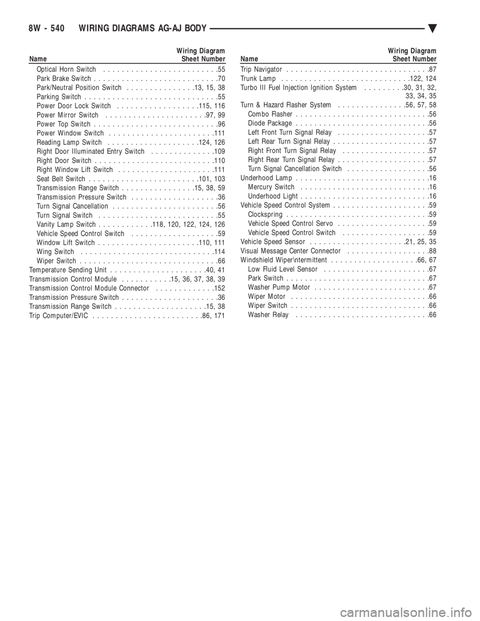
Wiring Diagram
Name Sheet Number
Optical Horn Switch .........................55
Park Brake Switch ...........................70
Park/Neutral Position Switch ...............13, 15, 38
Parking Switch .............................55
Power Door Lock Switch ..................115, 116
Power Mirror Switch ..................... .97, 99
Power Top Switch ...........................96
Power Window Switch ...................... .111
Reading Lamp Switch ................... .124, 126
Right Door Illuminated Entry Switch ..............109
Right Door Switch ......................... .110
Right Window Lift Switch .................... .111
Seat Belt Switch ....................... .101, 103
Transmission Range Switch ................15, 38, 59
Transmission Pressure Switch ...................36
Turn Signal Cancellation .......................56
Turn Signal Switch ..........................55
Vanity Lamp Switch ............118, 120, 122, 124, 126
Vehicle Speed Control Switch ...................59
Window Lift Switch ..................... .110, 111
Wing Switch ............................ .114
Wiper Switch ..............................66
Temperature Sending Unit .................... .40, 41
Transmission Control Module ...........15, 36, 37, 38, 39
Transmission Control Module Connector .............152
Transmission Pressure Switch .....................36
Transmission Range Switch ................... .15, 38
Trip Computer/EVIC ....................... .86, 171Wiring Diagram
Name Sheet Number
Trip Navigator ...............................87
Trunk Lamp ........................... .122, 124
Turbo III Fuel Injection Ignition System .........30, 31, 32,
33, 34, 35
Turn & Hazard Flasher System ...............56, 57, 58
Combo Flasher .............................56
Diode Package .............................56
Left Front Turn Signal Relay ....................57
Left Rear Turn Signal Relay .....................57
Right Front Turn Signal Relay ...................57
Right Rear Turn Signal Relay ....................57
Turn Signal Cancellation Switch ..................56
Underhood Lamp .............................16
Mercury Switch ............................16
Underhood Light ............................16
Vehicle Speed Control System .....................59
Clockspring ...............................59
Vehicle Speed Control Servo ....................59
Vehicle Speed Control Switch ...................59
Vehicle Speed Sensor .................... .21, 25, 35
Visual Message Center Connector ..................88
Windshield Wiper
termittent ...................66, 67
Low Fluid Level Sensor .......................67
Park Switch ...............................67
Washer Pump Motor .........................67
Wiper Motor ..............................66
Wiper Switch ..............................66
Washer Relay .............................66
8W - 540 WIRING DIAGRAMS AG-AJ BODY Ä
Page 1469 of 2438
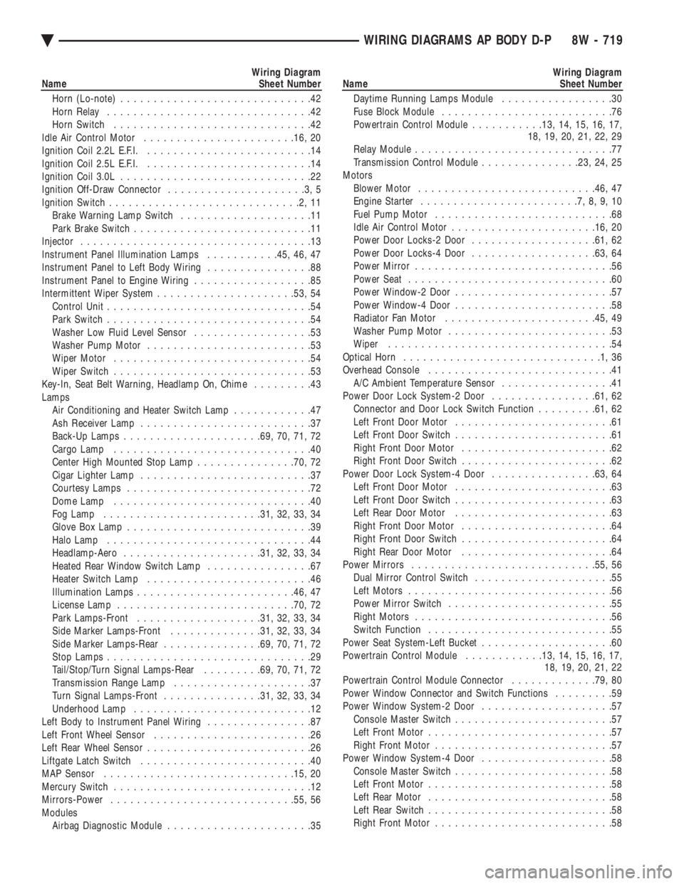
Wiring Diagram
Name Sheet Number
Horn (Lo-note) .............................42
Horn Relay ...............................42
Horn Switch ..............................42
Idle Air Control Motor ...................... .16, 20
Ignition Coil 2.2L E.F.I. .........................14
Ignition Coil 2.5L E.F.I. .........................14
Ignition Coil 3.0L .............................22
Ignition Off-Draw Connector .....................3,5
Ignition Switch .............................2,11
Brake Warning Lamp Switch ....................11
Park Brake Switch ...........................11
Injector ...................................13
Instrument Panel Illumination Lamps ...........45, 46, 47
Instrument Panel to Left Body Wiring ................88
Instrument Panel to Engine Wiring ..................85
Intermittent Wiper System .................... .53, 54
Control Unit ...............................54
Park Switch ...............................54
Washer Low Fluid Level Sensor ..................53
Washer Pump Motor .........................53
Wiper Motor ..............................54
Wiper Switch ..............................53
Key-In, Seat Belt Warning, Headlamp On, Chime .........43
Lamps Air Conditioning and Heater Switch Lamp ............47
Ash Receiver Lamp ..........................37
Back-Up Lamps .................... .69, 70, 71, 72
Cargo Lamp ..............................40
Center High Mounted Stop Lamp ...............70, 72
Cigar Lighter Lamp ..........................37
Courtesy Lamps ............................72
Dome Lamp ..............................40
Fog Lamp ....................... .31, 32, 33, 34
Glove Box Lamp ............................39
Halo Lamp ...............................44
Headlamp-Aero .................... .31, 32, 33, 34
Heated Rear Window Switch Lamp ................67
Heater Switch Lamp .........................46
Illumination Lamps ....................... .46, 47
License Lamp .......................... .70, 72
Park Lamps-Front .................. .31, 32, 33, 34
Side Marker Lamps-Front ..............31, 32, 33, 34
Side Marker Lamps-Rear ...............69, 70, 71, 72
Stop Lamps ...............................29
Tail/Stop/Turn Signal Lamps-Rear .........69, 70, 71, 72
Transmission Range Lamp .....................37
Turn Signal Lamps-Front ...............31, 32, 33, 34
Underhood Lamp ...........................12
Left Body to Instrument Panel Wiring ................87
Left Front Wheel Sensor ........................26
Left Rear Wheel Sensor .........................26
Liftgate Latch Switch ..........................40
MAP Sensor ............................ .15, 20
Mercury Switch ..............................12
Mirrors-Power ........................... .55, 56
Modules Airbag Diagnostic Module ......................35Wiring Diagram
Name Sheet Number
Daytime Running Lamps Module .................30
Fuse Block Module ..........................76
Powertrain Control Module ...........13, 14, 15, 16, 17,
18, 19, 20, 21, 22, 29
Relay Module ..............................77
Transmission Control Module ...............23, 24, 25
Motors Blower Motor .......................... .46, 47
Engine Starter ........................7,8,9,10
Fuel Pump Motor ...........................68
Idle Air Control Motor ..................... .16, 20
Power Door Locks-2 Door .................. .61, 62
Power Door Locks-4 Door .................. .63, 64
Power Mirror ..............................56
Power Seat ...............................60
Power Window-2 Door ........................57
Power Window-4 Door ........................58
Radiator Fan Motor ...................... .45, 49
Washer Pump Motor .........................53
Wiper ..................................54
Optical Horn ..............................1,36
Overhead Console ............................41
A/C Ambient Temperature Sensor .................41
Power Door Lock System-2 Door ................61, 62
Connector and Door Lock Switch Function .........61, 62
Left Front Door Motor ........................61
Left Front Door Switch ........................61
Right Front Door Motor .......................62
Right Front Door Switch .......................62
Power Door Lock System-4 Door ................63, 64
Left Front Door Motor ........................63
Left Front Door Switch ........................63
Left Rear Door Motor ........................63
Right Front Door Motor .......................64
Right Front Door Switch .......................64
Right Rear Door Motor .......................64
Power Mirrors ........................... .55, 56
Dual Mirror Control Switch .....................55
Left Motors ...............................56
Power Mirror Switch .........................55
Right Motors ..............................56
Switch Function ............................55
Power Seat System-Left Bucket ....................60
Powertrain Control Module ............13, 14, 15, 16, 17,
18, 19, 20, 21, 22
Powertrain Control Module Connector .............79, 80
Power Window Connector and Switch Functions .........59
Power Window System-2 Door ....................57
Console Master Switch ........................57
Left Front Motor ............................57
Right Front Motor ...........................57
Power Window System-4 Door ....................58
Console Master Switch ........................58
Left Front Motor ............................58
Left Rear Motor ............................58
Left Rear Switch ............................58
Right Front Motor ...........................58
Ä WIRING DIAGRAMS AP BODY D-P 8W - 719
Page 2000 of 2438
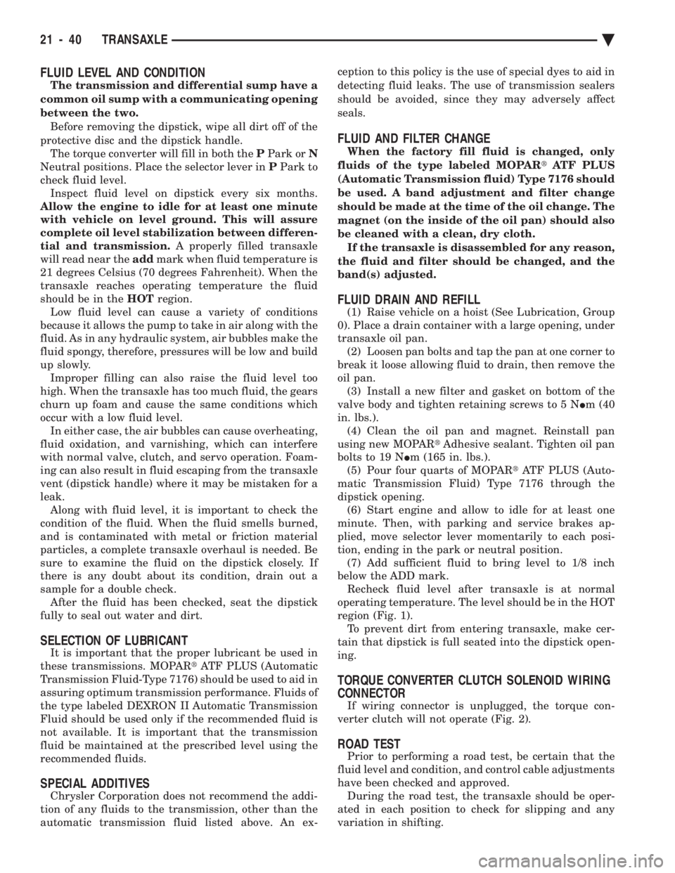
FLUID LEVEL AND CONDITION
The transmission and differential sump have a
common oil sump with a communicating opening
between the two. Before removing the dipstick, wipe all dirt off of the
protective disc and the dipstick handle. The torque converter will fill in both the PPark or N
Neutral positions. Place the selector lever in PPark to
check fluid level. Inspect fluid level on dipstick every six months.
Allow the engine to idle for at least one minute
with vehicle on level ground. This will assure
complete oil level stabilization between differen-
tial and transmission. A properly filled transaxle
will read near the addmark when fluid temperature is
21 degrees Celsius (70 degrees Fahrenheit). When the
transaxle reaches operating temperature the fluid
should be in the HOTregion.
Low fluid level can cause a variety of conditions
because it allows the pump to take in air along with the
fluid. As in any hydraulic system, air bubbles make the
fluid spongy, therefore, pressures will be low and build
up slowly. Improper filling can also raise the fluid level too
high. When the transaxle has too much fluid, the gears
churn up foam and cause the same conditions which
occur with a low fluid level. In either case, the air bubbles can cause overheating,
fluid oxidation, and varnishing, which can interfere
with normal valve, clutch, and servo operation. Foam-
ing can also result in fluid escaping from the transaxle
vent (dipstick handle) where it may be mistaken for a
leak. Along with fluid level, it is important to check the
condition of the fluid. When the fluid smells burned,
and is contaminated with metal or friction material
particles, a complete transaxle overhaul is needed. Be
sure to examine the fluid on the dipstick closely. If
there is any doubt about its condition, drain out a
sample for a double check. After the fluid has been checked, seat the dipstick
fully to seal out water and dirt.
SELECTION OF LUBRICANT
It is important that the proper lubricant be used in
these transmissions. MOPAR tATF PLUS (Automatic
Transmission Fluid-Type 7176) should be used to aid in
assuring optimum transmission performance. Fluids of
the type labeled DEXRON II Automatic Transmission
Fluid should be used only if the recommended fluid is
not available. It is important that the transmission
fluid be maintained at the prescribed level using the
recommended fluids.
SPECIAL ADDITIVES
Chrysler Corporation does not recommend the addi-
tion of any fluids to the transmission, other than the
automatic transmission fluid listed above. An ex- ception to this policy is the use of special dyes to aid in
detecting fluid leaks. The use of transmission sealers
should be avoided, since they may adversely affect
seals.
FLUID AND FILTER CHANGE
When the factory fill fluid is changed, only
fluids of the type labeled MOPAR tATF PLUS
(Automatic Transmission fluid) Type 7176 should
be used. A band adjustment and filter change
should be made at the time of the oil change. The
magnet (on the inside of the oil pan) should also
be cleaned with a clean, dry cloth. If the transaxle is disassembled for any reason,
the fluid and filter should be changed, and the
band(s) adjusted.
FLUID DRAIN AND REFILL
(1) Raise vehicle on a hoist (See Lubrication, Group
0). Place a drain container with a large opening, under
transaxle oil pan. (2) Loosen pan bolts and tap the pan at one corner to
break it loose allowing fluid to drain, then remove the
oil pan. (3) Install a new filter and gasket on bottom of the
valve body and tighten retaining screws to 5 N Im (40
in. lbs.). (4) Clean the oil pan and magnet. Reinstall pan
using new MOPAR tAdhesive sealant. Tighten oil pan
bolts to 19 N Im (165 in. lbs.).
(5) Pour four quarts of MOPAR tATF PLUS (Auto-
matic Transmission Fluid) Type 7176 through the
dipstick opening. (6) Start engine and allow to idle for at least one
minute. Then, with parking and service brakes ap-
plied, move selector lever momentarily to each posi-
tion, ending in the park or neutral position. (7) Add sufficient fluid to bring level to 1/8 inch
below the ADD mark. Recheck fluid level after transaxle is at normal
operating temperature. The level should be in the HOT
region (Fig. 1). To prevent dirt from entering transaxle, make cer-
tain that dipstick is full seated into the dipstick open-
ing.
TORQUE CONVERTER CLUTCH SOLENOID WIRING
CONNECTOR
If wiring connector is unplugged, the torque con-
verter clutch will not operate (Fig. 2).
ROAD TEST
Prior to performing a road test, be certain that the
fluid level and condition, and control cable adjustments
have been checked and approved. During the road test, the transaxle should be oper-
ated in each position to check for slipping and any
variation in shifting.
21 - 40 TRANSAXLE Ä
Page 2053 of 2438
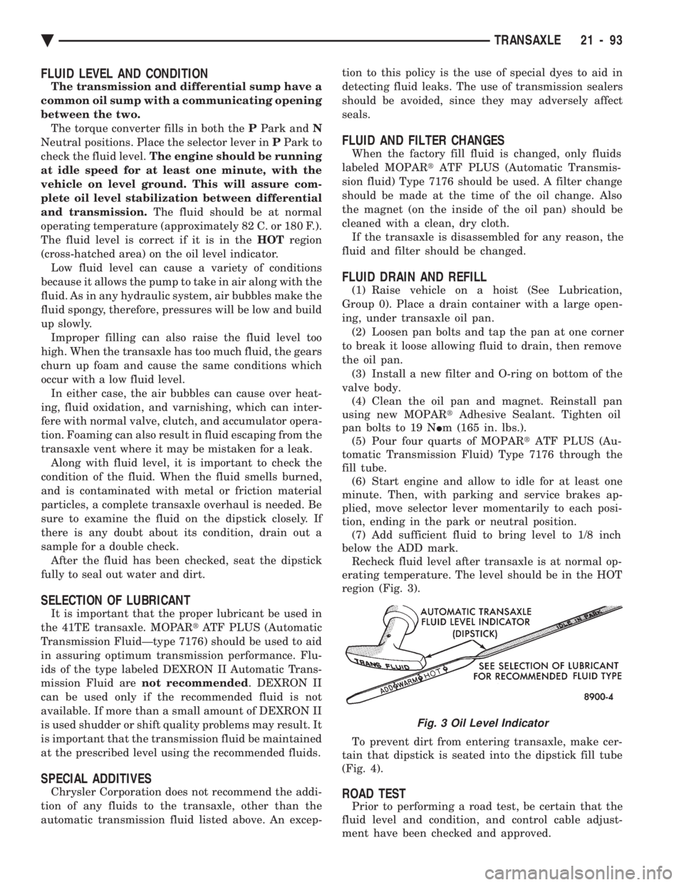
FLUID LEVEL AND CONDITION
The transmission and differential sump have a
common oil sump with a communicating opening
between the two. The torque converter fills in both the PPark and N
Neutral positions. Place the selector lever in PPark to
check the fluid level. The engine should be running
at idle speed for at least one minute, with the
vehicle on level ground. This will assure com-
plete oil level stabilization between differential
and transmission. The fluid should be at normal
operating temperature (approximately 82 C. or 180 F.).
The fluid level is correct if it is in the HOTregion
(cross-hatched area) on the oil level indicator. Low fluid level can cause a variety of conditions
because it allows the pump to take in air along with the
fluid. As in any hydraulic system, air bubbles make the
fluid spongy, therefore, pressures will be low and build
up slowly. Improper filling can also raise the fluid level too
high. When the transaxle has too much fluid, the gears
churn up foam and cause the same conditions which
occur with a low fluid level. In either case, the air bubbles can cause over heat-
ing, fluid oxidation, and varnishing, which can inter-
fere with normal valve, clutch, and accumulator opera-
tion. Foaming can also result in fluid escaping from the
transaxle vent where it may be mistaken for a leak. Along with fluid level, it is important to check the
condition of the fluid. When the fluid smells burned,
and is contaminated with metal or friction material
particles, a complete transaxle overhaul is needed. Be
sure to examine the fluid on the dipstick closely. If
there is any doubt about its condition, drain out a
sample for a double check. After the fluid has been checked, seat the dipstick
fully to seal out water and dirt.
SELECTION OF LUBRICANT
It is important that the proper lubricant be used in
the 41TE transaxle. MOPAR tATF PLUS (Automatic
Transmission FluidÐtype 7176) should be used to aid
in assuring optimum transmission performance. Flu-
ids of the type labeled DEXRON II Automatic Trans-
mission Fluid are not recommended . DEXRON II
can be used only if the recommended fluid is not
available. If more than a small amount of DEXRON II
is used shudder or shift quality problems may result. It
is important that the transmission fluid be maintained
at the prescribed level using the recommended fluids.
SPECIAL ADDITIVES
Chrysler Corporation does not recommend the addi-
tion of any fluids to the transaxle, other than the
automatic transmission fluid listed above. An excep- tion to this policy is the use of special dyes to aid in
detecting fluid leaks. The use of transmission sealers
should be avoided, since they may adversely affect
seals.
FLUID AND FILTER CHANGES
When the factory fill fluid is changed, only fluids
labeled MOPAR tATF PLUS (Automatic Transmis-
sion fluid) Type 7176 should be used. A filter change
should be made at the time of the oil change. Also
the magnet (on the inside of the oil pan) should be
cleaned with a clean, dry cloth. If the transaxle is disassembled for any reason, the
fluid and filter should be changed.
FLUID DRAIN AND REFILL
(1) Raise vehicle on a hoist (See Lubrication,
Group 0). Place a drain container with a large open-
ing, under transaxle oil pan. (2) Loosen pan bolts and tap the pan at one corner
to break it loose allowing fluid to drain, then remove
the oil pan. (3) Install a new filter and O-ring on bottom of the
valve body. (4) Clean the oil pan and magnet. Reinstall pan
using new MOPAR tAdhesive Sealant. Tighten oil
pan bolts to 19 N Im (165 in. lbs.).
(5) Pour four quarts of MOPAR tATF PLUS (Au-
tomatic Transmission Fluid) Type 7176 through the
fill tube. (6) Start engine and allow to idle for at least one
minute. Then, with parking and service brakes ap-
plied, move selector lever momentarily to each posi-
tion, ending in the park or neutral position. (7) Add sufficient fluid to bring level to 1/8 inch
below the ADD mark. Recheck fluid level after transaxle is at normal op-
erating temperature. The level should be in the HOT
region (Fig. 3).
To prevent dirt from entering transaxle, make cer-
tain that dipstick is seated into the dipstick fill tube
(Fig. 4).
ROAD TEST
Prior to performing a road test, be certain that the
fluid level and condition, and control cable adjust-
ment have been checked and approved.
Fig. 3 Oil Level Indicator
Ä TRANSAXLE 21 - 93
Page 2055 of 2438
(5) This test checks pump output, pressure regula-
tion and condition of the low/reverse clutch hydraulic
circuit and shift schedule.
TEST TWO-SELECTOR IN DRIVE 2ND GEAR
(1) Attach gauge to the underdrive clutch tap.
(2) Move selector lever to the 3position.
(3) Allow vehicle wheels to turn and increase
throttle opening to achieve an indicated vehicle
speed of 30 mph. (4) Underdrive clutch pressure should read 110 to
145 psi. (5) This test checks the underdrive clutch hydrau-
lic circuit as well as the shift schedule.
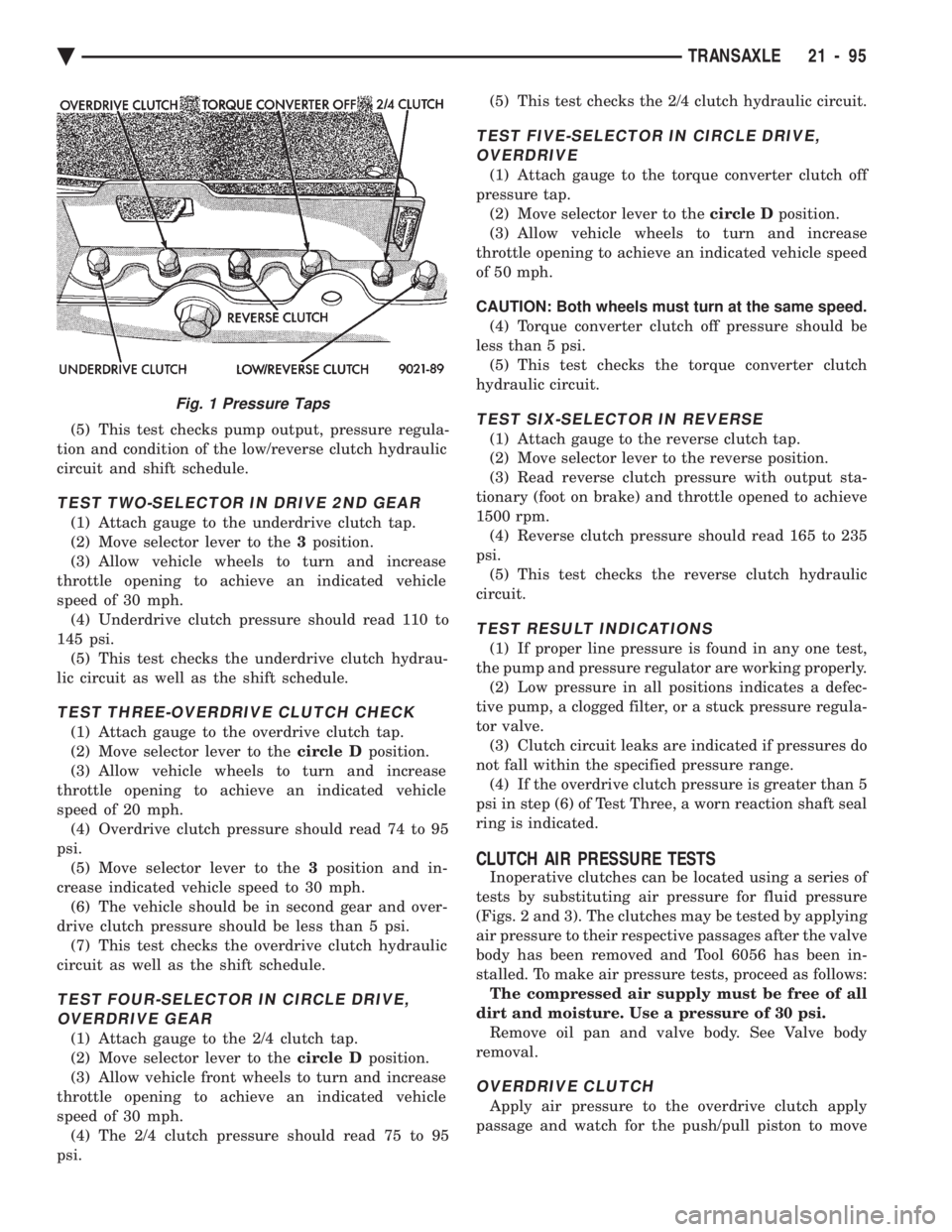
TEST THREE-OVERDRIVE CLUTCH CHECK
(1) Attach gauge to the overdrive clutch tap.
(2) Move selector lever to the circle Dposition.
(3) Allow vehicle wheels to turn and increase
throttle opening to achieve an indicated vehicle
speed of 20 mph. (4) Overdrive clutch pressure should read 74 to 95
psi. (5) Move selector lever to the 3position and in-
crease indicated vehicle speed to 30 mph. (6) The vehicle should be in second gear and over-
drive clutch pressure should be less than 5 psi. (7) This test checks the overdrive clutch hydraulic
circuit as well as the shift schedule.
TEST FOUR-SELECTOR IN CIRCLE DRIVE, OVERDRIVE GEAR
(1) Attach gauge to the 2/4 clutch tap.
(2) Move selector lever to the circle Dposition.
(3) Allow vehicle front wheels to turn and increase
throttle opening to achieve an indicated vehicle
speed of 30 mph. (4) The 2/4 clutch pressure should read 75 to 95
psi. (5) This test checks the 2/4 clutch hydraulic circuit.
TEST FIVE-SELECTOR IN CIRCLE DRIVE,
OVERDRIVE
(1) Attach gauge to the torque converter clutch off
pressure tap. (2) Move selector lever to the circle Dposition.
(3) Allow vehicle wheels to turn and increase
throttle opening to achieve an indicated vehicle speed
of 50 mph.
CAUTION: Both wheels must turn at the same speed. (4) Torque converter clutch off pressure should be
less than 5 psi. (5) This test checks the torque converter clutch
hydraulic circuit.
TEST SIX-SELECTOR IN REVERSE
(1) Attach gauge to the reverse clutch tap.
(2) Move selector lever to the reverse position.
(3) Read reverse clutch pressure with output sta-
tionary (foot on brake) and throttle opened to achieve
1500 rpm. (4) Reverse clutch pressure should read 165 to 235
psi. (5) This test checks the reverse clutch hydraulic
circuit.
TEST RESULT INDICATIONS
(1) If proper line pressure is found in any one test,
the pump and pressure regulator are working properly. (2) Low pressure in all positions indicates a defec-
tive pump, a clogged filter, or a stuck pressure regula-
tor valve. (3) Clutch circuit leaks are indicated if pressures do
not fall within the specified pressure range. (4) If the overdrive clutch pressure is greater than 5
psi in step (6) of Test Three, a worn reaction shaft seal
ring is indicated.
CLUTCH AIR PRESSURE TESTS
Inoperative clutches can be located using a series of
tests by substituting air pressure for fluid pressure
(Figs. 2 and 3). The clutches may be tested by applying
air pressure to their respective passages after the valve
body has been removed and Tool 6056 has been in-
stalled. To make air pressure tests, proceed as follows: The compressed air supply must be free of all
dirt and moisture. Use a pressure of 30 psi. Remove oil pan and valve body. See Valve body
removal.
OVERDRIVE CLUTCH
Apply air pressure to the overdrive clutch apply
passage and watch for the push/pull piston to move
Fig. 1 Pressure Taps
Ä TRANSAXLE 21 - 95
Page 2058 of 2438
CAUTION: Prevent manual shaft rotation during in-
stallation and removal. (2) With rotary motion, install converter hub seal
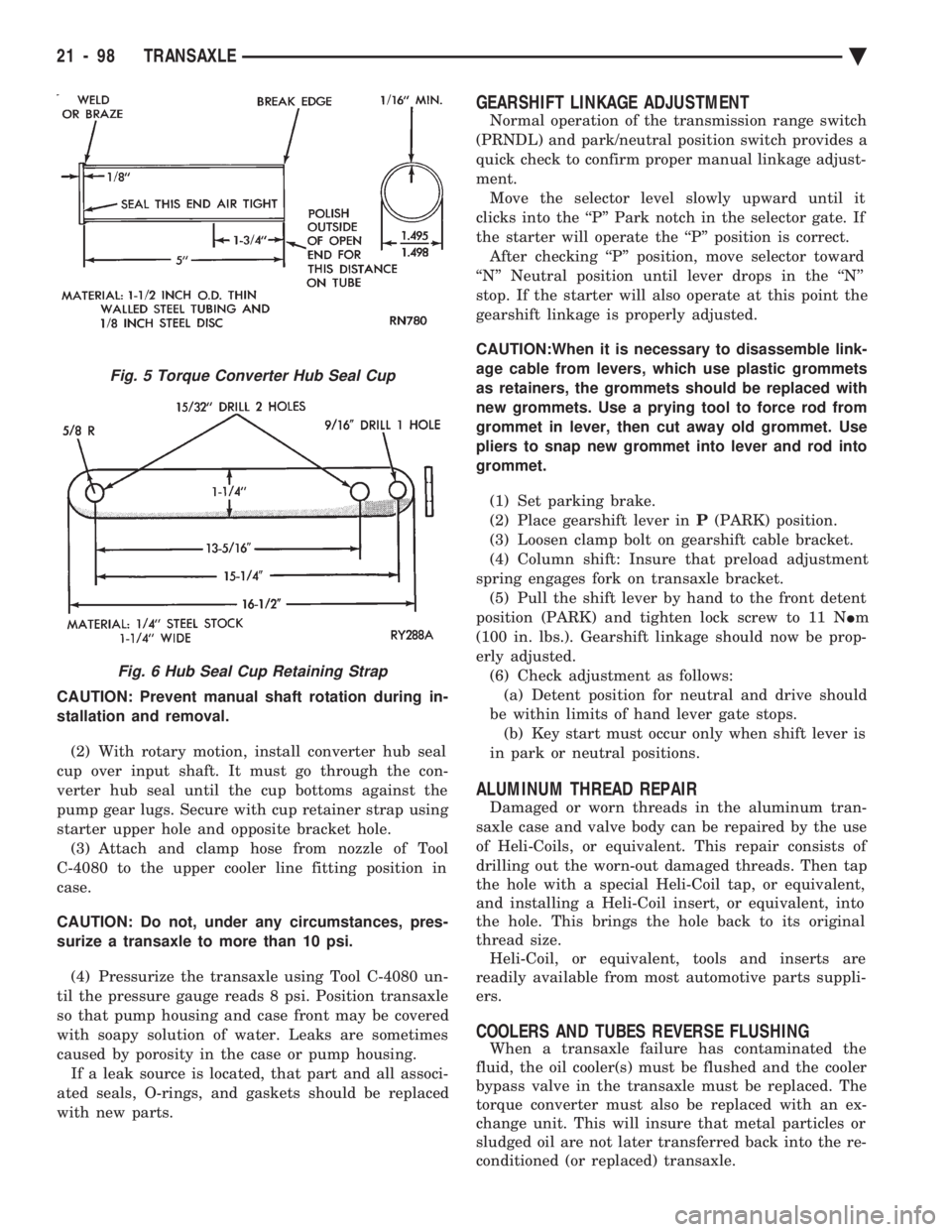
cup over input shaft. It must go through the con-
verter hub seal until the cup bottoms against the
pump gear lugs. Secure with cup retainer strap using
starter upper hole and opposite bracket hole. (3) Attach and clamp hose from nozzle of Tool
C-4080 to the upper cooler line fitting position in
case.
CAUTION: Do not, under any circumstances, pres-
surize a transaxle to more than 10 psi.
(4) Pressurize the transaxle using Tool C-4080 un-
til the pressure gauge reads 8 psi. Position transaxle
so that pump housing and case front may be covered
with soapy solution of water. Leaks are sometimes
caused by porosity in the case or pump housing. If a leak source is located, that part and all associ-
ated seals, O-rings, and gaskets should be replaced
with new parts.
GEARSHIFT LINKAGE ADJUSTMENT
Normal operation of the transmission range switch
(PRNDL) and park/neutral position switch provides a
quick check to confirm proper manual linkage adjust-
ment. Move the selector level slowly upward until it
clicks into the ``P'' Park notch in the selector gate. If
the starter will operate the ``P'' position is correct. After checking ``P'' position, move selector toward
``N'' Neutral position until lever drops in the ``N''
stop. If the starter will also operate at this point the
gearshift linkage is properly adjusted.
CAUTION:When it is necessary to disassemble link-
age cable from levers, which use plastic grommets
as retainers, the grommets should be replaced with
new grommets. Use a prying tool to force rod from
grommet in lever, then cut away old grommet. Use
pliers to snap new grommet into lever and rod into
grommet.
(1) Set parking brake.
(2) Place gearshift lever in P(PARK) position.
(3) Loosen clamp bolt on gearshift cable bracket.
(4) Column shift: Insure that preload adjustment
spring engages fork on transaxle bracket. (5) Pull the shift lever by hand to the front detent
position (PARK) and tighten lock screw to 11 N Im
(100 in. lbs.). Gearshift linkage should now be prop-
erly adjusted. (6) Check adjustment as follows:(a) Detent position for neutral and drive should
be within limits of hand lever gate stops. (b) Key start must occur only when shift lever is
in park or neutral positions.
ALUMINUM THREAD REPAIR
Damaged or worn threads in the aluminum tran-
saxle case and valve body can be repaired by the use
of Heli-Coils, or equivalent. This repair consists of
drilling out the worn-out damaged threads. Then tap
the hole with a special Heli-Coil tap, or equivalent,
and installing a Heli-Coil insert, or equivalent, into
the hole. This brings the hole back to its original
thread size. Heli-Coil, or equivalent, tools and inserts are
readily available from most automotive parts suppli-
ers.
COOLERS AND TUBES REVERSE FLUSHING
When a transaxle failure has contaminated the
fluid, the oil cooler(s) must be flushed and the cooler
bypass valve in the transaxle must be replaced. The
torque converter must also be replaced with an ex-
change unit. This will insure that metal particles or
sludged oil are not later transferred back into the re-
conditioned (or replaced) transaxle.
Fig. 5 Torque Converter Hub Seal Cup
Fig. 6 Hub Seal Cup Retaining Strap
21 - 98 TRANSAXLE Ä