fuel CHEVROLET DYNASTY 1993 User Guide
[x] Cancel search | Manufacturer: CHEVROLET, Model Year: 1993, Model line: DYNASTY, Model: CHEVROLET DYNASTY 1993Pages: 2438, PDF Size: 74.98 MB
Page 47 of 2438
tifreeze to achieve adequate protection. A mix table
on the coolant container indicates the amount of an-
tifreeze required to winterize the cooling system
based on the capacity, see Capacity Chart in General
Information section of this group.
SELECTING ANTIFREEZE
Chrysler Corporation recommends Mopar Anti-
freeze/Summer Coolant, or equivalent be used to win-
terize and protect cooling system.
RADIATOR CAP
The radiator cap must be secure to provide proper
pressure release and coolant recovery. Inspect and
test radiator cap when cooling system service is per-
formed or when problem is suspected.
COOLING SYSTEM SERVICE
The cooling system should be drained, flushed and
filled with the proper coolant mixture at the inter-
vals described in the Lubrication and Maintenance
Schedules. Refer to General Information section of
this group. For proper service instructions see Group
7, Cooling System.
ENGINE AIR CLEANER
The engine air cleaner should be serviced at the in-
tervals described in the Lubrication and Mainte-
nance Schedules. Refer to General Information
section of this group. Additional information can be
found in Group 14, Fuel System and Group 25, Emis-
sion System. Inspect all air cleaner hoses or tubes for
damage or leaks when other engine compartment
service is performed. Replace faulty components.
AIR CLEANER SERVICE
CAUTION: The air cleaner cover must be installed
properly for the emissions system and engine con-
troller to function correctly. Do not immerse paper air filter element or temper-
ature sensor in cleaning solvents, damage can re-
sult.
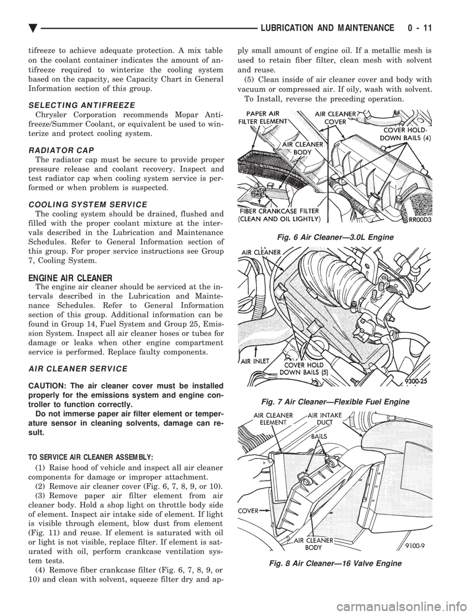
TO SERVICE AIR CLEANER ASSEMBLY: (1) Raise hood of vehicle and inspect all air cleaner
components for damage or improper attachment. (2) Remove air cleaner cover (Fig. 6, 7, 8, 9, or 10).
(3) Remove paper air filter element from air
cleaner body. Hold a shop light on throttle body side
of element. Inspect air intake side of element. If light
is visible through element, blow dust from element
(Fig. 11) and reuse. If element is saturated with oil
or light is not visible, replace filter. If element is sat-
urated with oil, perform crankcase ventilation sys-
tem tests. (4) Remove fiber crankcase filter (Fig. 6, 7, 8, 9, or
10) and clean with solvent, squeeze filter dry and ap- ply small amount of engine oil. If a metallic mesh is
used to retain fiber filter, clean mesh with solvent
and reuse.
(5) Clean inside of air cleaner cover and body with
vacuum or compressed air. If oily, wash with solvent. To Install, reverse the preceding operation.
Fig. 6 Air CleanerÐ3.0L Engine
Fig. 7 Air CleanerÐFlexible Fuel Engine
Fig. 8 Air CleanerÐ16 Valve Engine
Ä LUBRICATION AND MAINTENANCE 0 - 11
Page 49 of 2438
CRANKCASE VENTILATION SYSTEM
Engine crankcase pressure and emissions are
vented into combustion chambers through the posi-
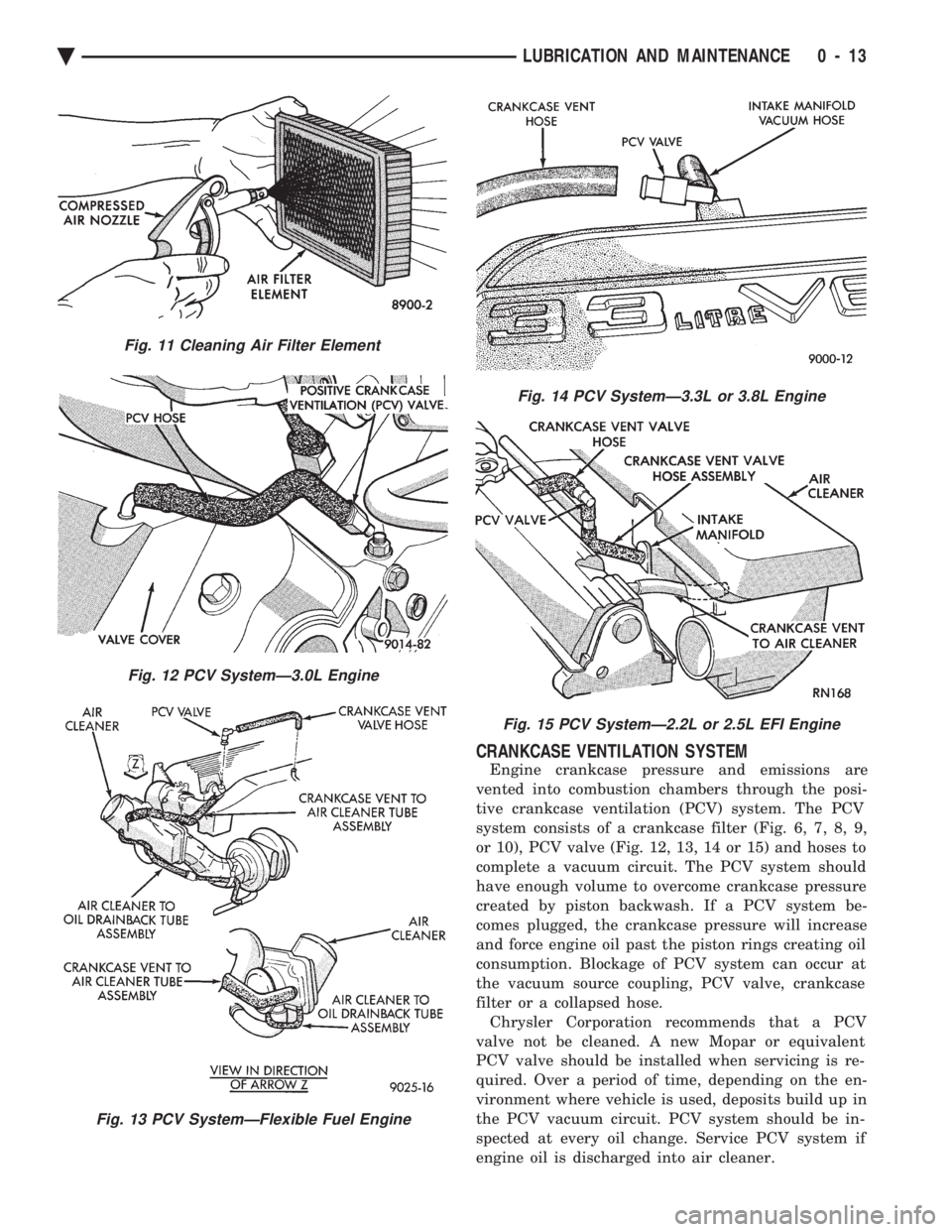
tive crankcase ventilation (PCV) system. The PCV
system consists of a crankcase filter (Fig. 6, 7, 8, 9,
or 10), PCV valve (Fig. 12, 13, 14 or 15) and hoses to
complete a vacuum circuit. The PCV system should
have enough volume to overcome crankcase pressure
created by piston backwash. If a PCV system be-
comes plugged, the crankcase pressure will increase
and force engine oil past the piston rings creating oil
consumption. Blockage of PCV system can occur at
the vacuum source coupling, PCV valve, crankcase
filter or a collapsed hose. Chrysler Corporation recommends that a PCV
valve not be cleaned. A new Mopar or equivalent
PCV valve should be installed when servicing is re-
quired. Over a period of time, depending on the en-
vironment where vehicle is used, deposits build up in
the PCV vacuum circuit. PCV system should be in-
spected at every oil change. Service PCV system if
engine oil is discharged into air cleaner.
Fig. 11 Cleaning Air Filter Element
Fig. 12 PCV SystemÐ3.0L Engine
Fig. 13 PCV SystemÐFlexible Fuel Engine
Fig. 14 PCV SystemÐ3.3L or 3.8L Engine
Fig. 15 PCV SystemÐ2.2L or 2.5L EFI Engine
Ä LUBRICATION AND MAINTENANCE 0 - 13
Page 50 of 2438
PCV SYSTEM TEST
Refer to group 25, Emission Control System for
proper procedures to test PCV system.
FUEL RECOMMENDATIONS
Chrysler Corporation recommends that only fuel pur-
chased from a reputable retailer be used. Use high qual-
ity, unleaded gasoline to provide satisfactory
driveability and highest fuel economy. Gasoline contain-
ing detergent and corrosion control additives are desire-
able. If the engine develops spark knock (audible ping),
poor performance, hard starting or stalling, purchase
fuel from another source. Engine performance can vary
when using different brands of gasoline with the same
octane rating. Occasional light engine spark knock un-
der heavy acceleration, at low speed or when vehicle is
heavily loaded is not harmful. Extended periods of
spark knock under moderate acceleration or at cruising
speed can damage the engine. The cause of excessive
spark knock condition must be diagnosed and corrected.
For diagnostic procedures refer to Group 14, Fuel Sys-
tem and Powertrain Diagnostic Procedures manual.
SELECTING GASOLINE
CAUTION:Do not use fuel containing METHANOL
(methyl or wood alcohol), damage to fuel system
will result. Do not use leaded gasoline, damage to catalytic
converter will result and vehicle will not conform to
emission control standards.
ETHANOL, MTBE OR ETBE BLENDS
All Chrysler Corporation vehicles are designed to
use unleaded gasoline ONLY. Gasohol blends, con-
taining 10% Ethanol (ethyl or grain alcohol) 90% un-
leaded gasoline can be used provided it has adequate
octane rating. Fuel blends containing up to 15% MTBE (Methyl
Tertiary Butyl Ether) and 85% unleaded gasoline can
be used. Fuel blends containing up to 17% ETBE
(Ethyl Tertiary Butyl Ether) and 83% unleaded gas-
oline can also be used. Fuel blended with ethanol, MTBE or ETBE are
also referred to as reformulated or clean air gasoline.
These fuels contribute less emissions to the atmo-
sphere. Chrysler Corporation recommends that
blended fuels be used when available
METHANOL BLENDS Using gasoline blended with methanol can result
in starting and driveability problems. Deterioration
of fuel system components will result. Methanol in-
duced problems are not the responsibility of Chrysler
Corporation and may not be covered by the vehicle
warranty. NON-TURBOCHARGED ENGINES
Use regular unleaded gasoline having a minimum
octane rating of 87 (R+M)/2. Higher octane premium
unleaded gasoline can be used if desired.
2.2L 16 VALVE TURBOCHARGED ENGINE
Use premium unleaded gasoline having a mini-
mum octane rating of 91 (R+M)/2. Gasoline with oc-
tane rating less than 91 (R+M)/2 can be used if
recommended gasoline is not available. Low octane
gasoline will reduce engine performance.
FLEXIBLE FUEL VEHICLES
CAUTION: Do not use 100% methanol, damage to
fuel system can result. Use unleaded regular gasoline having a minimum
octane rating of 87 (R=M)/2 and M85 fuel that is
85% methanol and 15% unleaded gasoline, or a mix-
ture of these two.
FUEL FILTER
The fuel filter requires service only when a fuel
contamination problem is suspected. For proper diag-
nostic and service procedures refer to Group 14, Fuel
System,
IGNITION CABLES, DISTRIBUTOR CAP, AND
ROTOR
Inspect and test ignition cables, distributor cap and
rotor when the spark plugs are replaced. Oil and
grime should be cleaned from the ignition cables and
distributor cap to avoid possible spark plug fouling.
Mopar, Foamy Engine Degreaser, or equivalent is
recommended for cleaning the engine compartment.
For proper service and diagnostic procedures refer to
Group 8D, Ignition System.
SPARK PLUGS
Ignition spark plugs should be replaced at the
mileage interval described in the Lubrication and
Maintenance Schedules. Refer to the General Infor-
mation section of this group. For proper service pro-
cedures refer to Group 8D, Ignition Systems.
DRIVE BELTS
Inspect and adjust drive belts at the interval de-
scribed in the Lubrication and Maintenance Sched-
ules. Refer to General Information section of this
group. For proper inspection and adjustment proce-
dures, see Group 7, Cooling System.
EMISSION CONTROL SYSTEM
Inspect all emission control components and hoses
when other under hood service is performed. Refer to
emission system Vacuum Hose Label located on the
0 - 14 LUBRICATION AND MAINTENANCE Ä
Page 51 of 2438
inside of the hood in the engine compartment and
Group 25, Emission Control Systems for proper ser-
vice procedures.
BATTERY
Inspect battery tray, hold down and terminal con-
nections when other under hood service is performed.
For proper diagnostic procedures refer to Group 8A,
Battery/Starting/Charging System Diagnostics. For
service and cleaning procedures refer to Group 8B,
Battery/Starter Service.
RUBBER AND PLASTIC COMPONENT INSPECTION
CAUTION: Plastic hoses or wire harness covers will
melt or deform when exposed to heat from exhaust
system or engine manifolds. Position plastic or rubber components away from
moving parts in engine compartment or under vehi-
cle, or damage will result. Do not allow rubber engine mounts or other com-
ponents to become oil contaminated, repair cause
of oil contamination and clean area. All rubber and plastic components should be in-
spected when engine compartment or under vehicle
service is performed. When evidence of deterioration
exists, replacement is required. To reduce deteriora-
tion of rubber components, Chrysler Corporation rec-
ommends Mopar Foamy Engine Degreaser or
equivalent be used to clean engine compartment of
oil and road grime.
EXHAUST SYSTEM ISOLATOR AND HANGER
The exhaust system should be inspected when un-
der vehicle service is performed. The exhaust system
should not make contact with under body, brake ca-
bles, brake/fuel lines, fuel tank or suspension compo-
nents. Slight cracking in rubber isolator or hanger is
acceptable. Severely cracked or broken rubber compo-
nents must be replaced. For proper service proce-
dures see Group 11, Exhaust System and Intake
Manifold.
Ä LUBRICATION AND MAINTENANCE 0 - 15
Page 58 of 2438
BRAKE RESERVOIR LEVEL INSPECTION
WARNING: DO NOT ALLOW PETROLEUM OR WATER
BASE LIQUIDS TO CONTAMINATE BRAKE FLUID,
SEAL DAMAGE AND BRAKE FAILURE CAN RESULT.
RELIEVE PRESSURE IN ANTI-LOCK BRAKE SYS-
TEM BEFORE ADDING BRAKE FLUID TO RESER-
VOIR. IF NOT, BRAKE FLUID COULD DISCHARGED
FROM THE RESERVOIR POSSIBLY CAUSING PER-
SONAL INJURY.
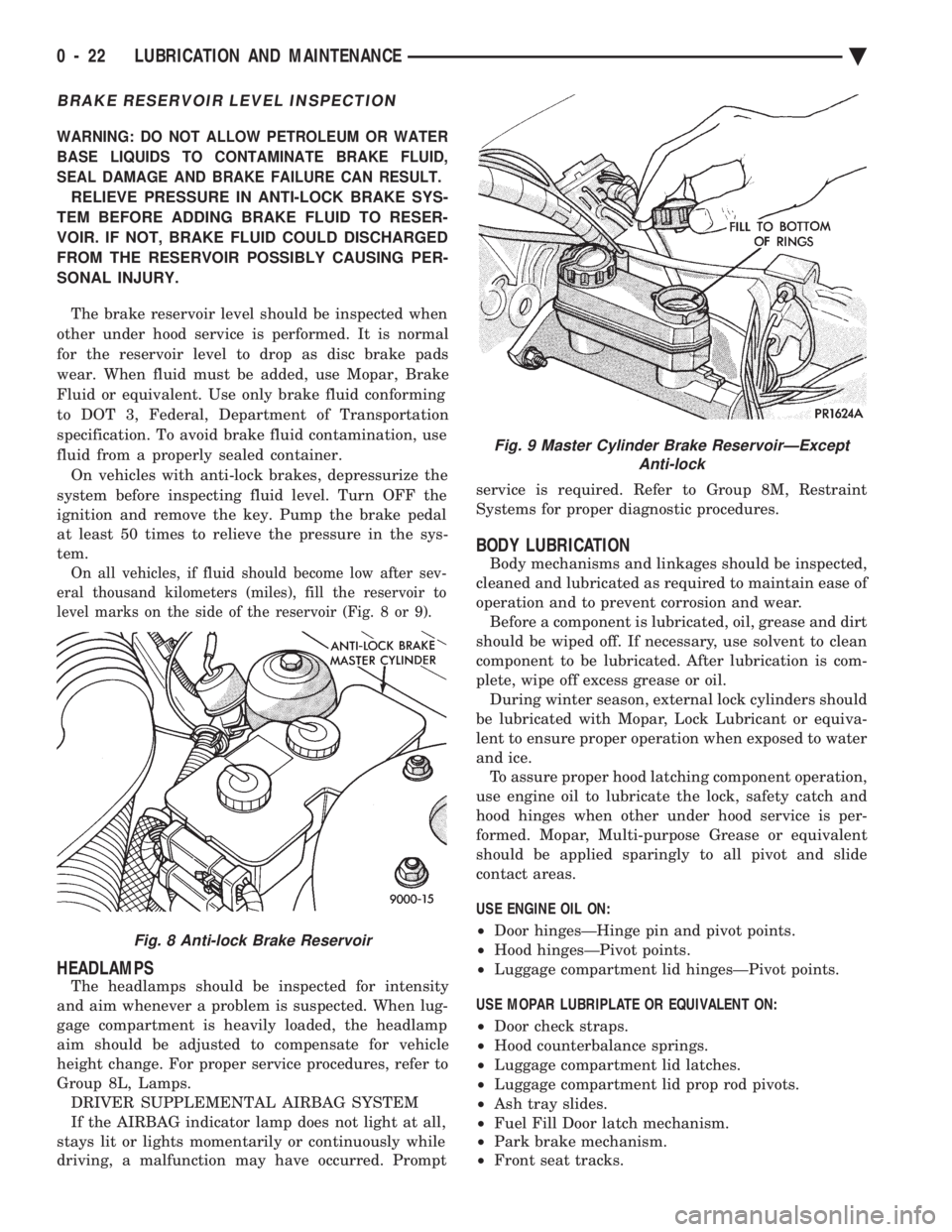
The brake reservoir level should be inspected when
other under hood service is performed. It is normal
for the reservoir level to drop as disc brake pads
wear. When fluid must be added, use Mopar, Brake
Fluid or equivalent. Use only brake fluid conforming
to DOT 3, Federal, Department of Transportation
specification. To avoid brake fluid contamination, use
fluid from a properly sealed container. On vehicles with anti-lock brakes, depressurize the
system before inspecting fluid level. Turn OFF the
ignition and remove the key. Pump the brake pedal
at least 50 times to relieve the pressure in the sys-
tem.
On all vehicles, if fluid should become low after sev-
eral thousand kilometers (miles), fill the reservoir to
level marks on the side of the reservoir (Fig. 8 or 9).
HEADLAMPS
The headlamps should be inspected for intensity
and aim whenever a problem is suspected. When lug-
gage compartment is heavily loaded, the headlamp
aim should be adjusted to compensate for vehicle
height change. For proper service procedures, refer to
Group 8L, Lamps. DRIVER SUPPLEMENTAL AIRBAG SYSTEM
If the AIRBAG indicator lamp does not light at all,
stays lit or lights momentarily or continuously while
driving, a malfunction may have occurred. Prompt service is required. Refer to Group 8M, Restraint
Systems for proper diagnostic procedures.
BODY LUBRICATION
Body mechanisms and linkages should be inspected,
cleaned and lubricated as required to maintain ease of
operation and to prevent corrosion and wear. Before a component is lubricated, oil, grease and dirt
should be wiped off. If necessary, use solvent to clean
component to be lubricated. After lubrication is com-
plete, wipe off excess grease or oil. During winter season, external lock cylinders should
be lubricated with Mopar, Lock Lubricant or equiva-
lent to ensure proper operation when exposed to water
and ice. To assure proper hood latching component operation,
use engine oil to lubricate the lock, safety catch and
hood hinges when other under hood service is per-
formed. Mopar, Multi-purpose Grease or equivalent
should be applied sparingly to all pivot and slide
contact areas.
USE ENGINE OIL ON:
² Door hingesÐHinge pin and pivot points.
² Hood hingesÐPivot points.
² Luggage compartment lid hingesÐPivot points.
USE MOPAR LUBRIPLATE OR EQUIVALENT ON:
² Door check straps.
² Hood counterbalance springs.
² Luggage compartment lid latches.
² Luggage compartment lid prop rod pivots.
² Ash tray slides.
² Fuel Fill Door latch mechanism.
² Park brake mechanism.
² Front seat tracks.
Fig. 8 Anti-lock Brake Reservoir
Fig. 9 Master Cylinder Brake ReservoirÐExcept
Anti-lock
0 - 22 LUBRICATION AND MAINTENANCE Ä
Page 63 of 2438
FRONT SUSPENSION SERVICE PROCEDURES INDEX
page page
Ball Joints .............................. 13
Hub and Bearing Assembly ................. 20
Knuckle (Front Suspension) ................. 16
Lower Control Arm ....................... 10
Lower Control Arm Pivot Bushings ........... 11 Shock Absorbers (Strut Damper)
............. 10
Strut Damper Assembly ..................... 7
Suspension Coil Springs .................... 9
Sway Bar .............................. 14
Wheel Alignment .......................... 5
WHEEL ALIGNMENT
Front wheel alignment is the proper adjustment of
all interrelated front suspension angles. These angles
are what affects the running and steering of the
front wheels of the vehicle. The method of checking front alignment will vary
depending on the type of equipment being used. The
instructions furnished by the manufacturer of the
equipment should always be followed. With the ex-
ception that the alignment specifications recom-
mended by Chrysler Corporation be used. There are six basic factors which are the founda-
tion to front wheel alignment. These are height,
caster, camber, toe-in, steering axis inclination and
toe-out on turns. Of the six basic factors only camber
and toe in are mechanically adjustable (Fig. 1)
CAUTION: Do not attempt to modify any suspen-
sion or steering components by heating or bending
of the component.
Wheel alignment adjustments and checks should be
made in the following sequence. (1) Camber
(2) Toe
Camber is the number of degrees the top of the
wheel is tilted inward or outward from true vertical.
Inward tilt is negative camber. Outward tilt is posi-
tive camber. Excessive camber is a tire wear factor: negative
camber causes wear on the inside of the tire, while
positive camber causes wear to the outside. Toe
is measured in degrees or inches and is the
distance the front edges of the tires are closer (or far-
ther apart) than the rear edges. See Front Wheel
Drive Specifications for Toesettings.
PRE-ALIGNMENT
Before any attempt is made to change or correct
the wheel alignment factors. The following inspection
and necessary corrections must be made on those
parts which influence the steering of the vehicle. (1) Check and inflate tires to recommended pres-
sure. All tires should be the same size and in good
condition and have approximately the same wear.
Note type of tread wear which will aid in diagnosing,
see Wheels and Tires, Group 22. (2) Check front wheel and tire assembly for radial
runout. (3) Inspect lower ball joints and all steering link-
age for looseness. (4) Check for broken or sagged front and rear
springs. Front suspension must only be checked after the
vehicle has had the following checked or adjusted.
Tires set to recommended pressures, full tank of fuel,
no passenger or luggage compartment load and is on
a level floor or alignment rack. Just prior to each alignment reading. The vehicle
should be bounced (rear first, then front) by grasping
bumper at center and jouncing each end an equal
number of times. Always release bumpers at bottom
of down cycle.
Ä SUSPENSION AND DRIVESHAFTS 2 - 5
Page 130 of 2438
CONTROL MODULE
REMOVAL
(1) Disconnect negative battery cable.
(2) Remove right side trunk trim panel.
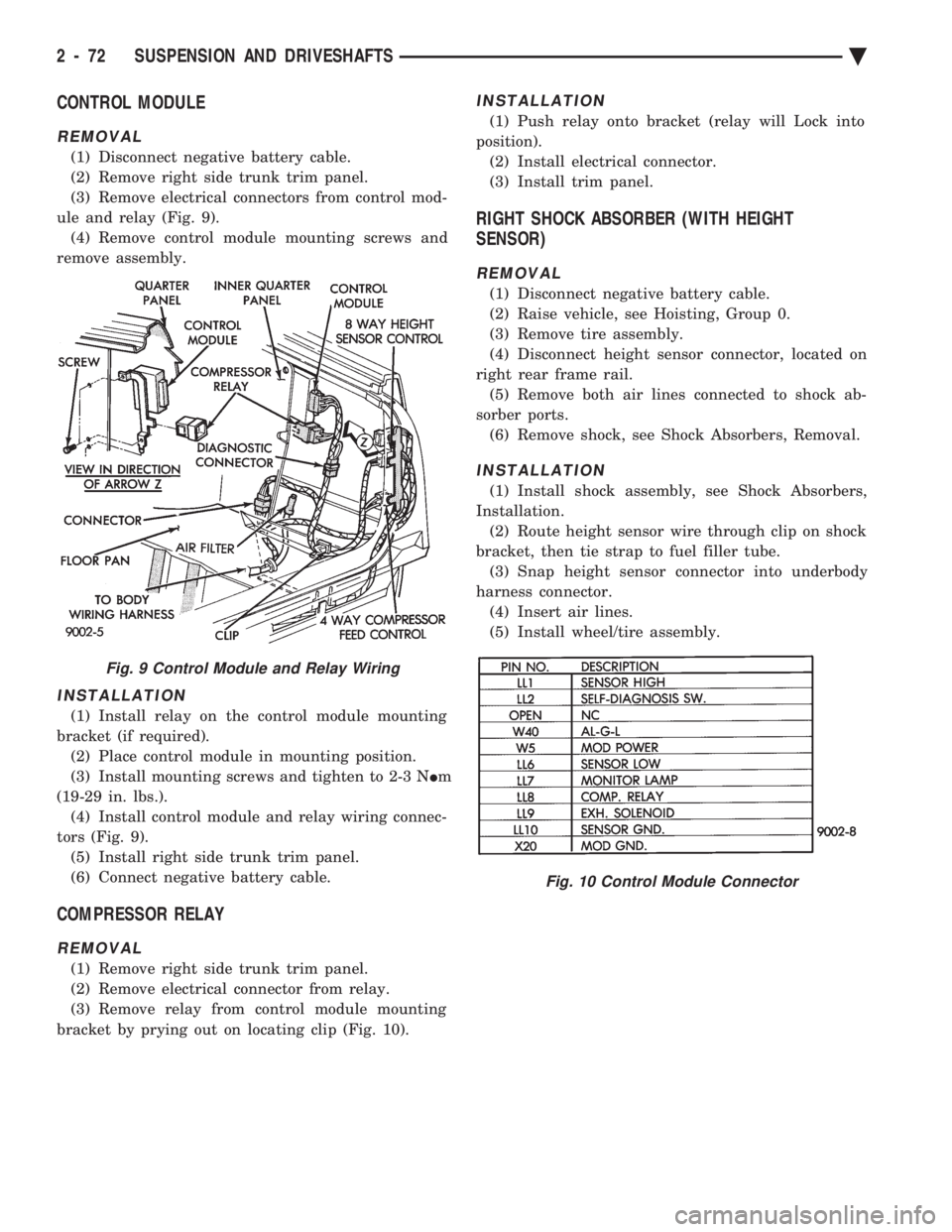
(3) Remove electrical connectors from control mod-
ule and relay (Fig. 9). (4) Remove control module mounting screws and
remove assembly.
INSTALLATION
(1) Install relay on the control module mounting
bracket (if required). (2) Place control module in mounting position.
(3) Install mounting screws and tighten to 2-3 N Im
(19-29 in. lbs.). (4) Install control module and relay wiring connec-
tors (Fig. 9). (5) Install right side trunk trim panel.
(6) Connect negative battery cable.
COMPRESSOR RELAY
REMOVAL
(1) Remove right side trunk trim panel.
(2) Remove electrical connector from relay.
(3) Remove relay from control module mounting
bracket by prying out on locating clip (Fig. 10).
INSTALLATION
(1) Push relay onto bracket (relay will Lock into
position). (2) Install electrical connector.
(3) Install trim panel.
RIGHT SHOCK ABSORBER (WITH HEIGHT
SENSOR)
REMOVAL
(1) Disconnect negative battery cable.
(2) Raise vehicle, see Hoisting, Group 0.
(3) Remove tire assembly.
(4) Disconnect height sensor connector, located on
right rear frame rail. (5) Remove both air lines connected to shock ab-
sorber ports. (6) Remove shock, see Shock Absorbers, Removal.
INSTALLATION
(1) Install shock assembly, see Shock Absorbers,
Installation. (2) Route height sensor wire through clip on shock
bracket, then tie strap to fuel filler tube. (3) Snap height sensor connector into underbody
harness connector. (4) Insert air lines.
(5) Install wheel/tire assembly.
Fig. 9 Control Module and Relay Wiring
Fig. 10 Control Module Connector
2 - 72 SUSPENSION AND DRIVESHAFTS Ä
Page 133 of 2438

and with internal valving maintains a residual pres-
sure of 172 to 276 kPa (25 to 40 psi).
AIR LINES
Nylon air lines (4) are routed from the compressor
(air dryer) to each strut/spring assembly. Rightside
strut and air spring air lines are routed with the fuel
lines. Leftside strut and air spring air lines are
routed across the vehicle (forward of the fuel tank).
And to the front of the vehicle with the brake lines
(Figs. 4 and 5).
Fig. 3 Air Compressor/Dryer Assembly
Fig. 4 Air Lines Front
Ä SUSPENSION AND DRIVESHAFTS 2 - 75
Page 146 of 2438
to 68 N Im (50 ft. lbs.) torque.
(7) Install wheel and tire assembly. Lower vehicle,
install wheel and tire assembly and connect battery
negative cable.
RIGHT SHOCK ABSORBER (WITH HEIGHT
SENSOR)
REMOVAL
(1) Disconnect battery negative cable.
(2) Raise vehicle, see Hoisting, Group 0.
(3) Remove tire assembly.
(4) Disconnect height sensor connector located on
right rear frame rail. (5) Remove shock, see Shock Absorbers, Removal.
INSTALLATION
(1) Install shock assembly, see Shock Absorbers,
Installation. (2) Route height sensor wire through retaining
clips and then tie strap to fuel filler tube. (3) Snap height sensor connector into underbody
harness connector. (4) Install wheel/tire assembly.
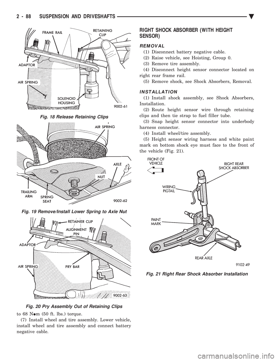
(5) Height sensor wiring harness and white paint
mark on bottom shock eye must face to the front of
the vehicle (Fig. 21).
Fig. 18 Release Retaining Clips
Fig. 19 Remove/Install Lower Spring to Axle Nut
Fig. 20 Pry Assembly Out of Retaining Clips
Fig. 21 Right Rear Shock Absorber Installation
2 - 88 SUSPENSION AND DRIVESHAFTS Ä
Page 364 of 2438
sends the message to the Engine Controller. The En-
gine Controller turns on the fan through the fan re-
lay. See Wiring Diagrams Manual for circuity and
diagnostics provided.Switching through the Engine Controller provides
fan control for the following conditions.
² The fan will not run during cranking until the en-
gine starts no matter what the coolant temperature
is.
² Fan will run when the air conditioning clutch is
engaged and low pressure cutout switch is closed.
² For 4 cylinder application the fan will run at ve-
hicle speeds above about 40 mph only if coolant tem-
perature reaches 110ÉC (230ÉF). It will turn off when
the temperature drops to 104ÉC (220ÉF). At speeds
below 40 mph the fan switches on at 102ÉC (215ÉF)
and off at 93ÉC (200ÉF).
² This is to help prevent steaming. The fan will run
only below 16ÉC (60ÉF) ambient. Between 38ÉC
(100ÉF) to 97ÉC (195ÉF) coolant temperature, at idle
and then only for three minutes.
RADIATOR FAN CONTROLÐAC/AY BODY V-6 ONLY
For this application, fan control is accomplished
based on coolant temperature, and on A/C head pres-
sure. These vehicles receive the variable displace-
ment compressor. The fan will go on when;
² Coolant temperature reaches 102ÉC (215ÉF) and off
at 93.4ÉC (200ÉF) regardless of vehicle speed.
² When the head pressure reaches 1516.9 kPa (220
psi) and turn off when the pressure reaches 1103 kPa
(160 psi).
TEMPERATURE GAUGE INDICATION
At idle the temperature gauge will rise slowly to
about 5/8 gauge travel. The fan will come on and the
gauge will drop to about 1/2 gauge travel, this is nor-
mal.
ELECTRIC FAN MOTOR
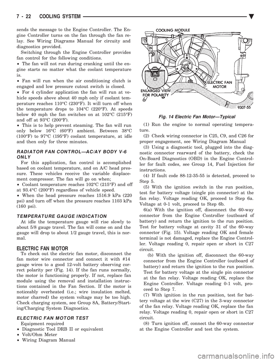
To check out the electric fan motor, disconnect the
fan motor wire connector and connect it with #14
gauge wires to a good 12-volt battery observing cor-
rect polarity per (Fig. 14). If the fan runs normally,
the motor is functioning properly. If not, replace fan
module using the removal and installation instruc-
tions contained in the Fan Section. If the motor is
noticeably overheated (i.e.; wire insulation melted,
motor charred) the system voltage may be too high.
Check charging system, see Group 8A, Battery/Start-
ing/Charging System Diagnostics.
ELECTRIC FAN MOTOR TEST
Equipment required
² Diagnostic Tool DRB II or equivalent
² Volt/Ohm Meter
² Wiring Diagram Manual (1) Run the engine to normal operating tempera-
ture. (2) Check wiring connector in C25, C9, and C26 for
proper engagement, see Wiring Diagram Manual (3) Using a diagnostic tool, plugged into the diag-
nostic connector rearward of the battery, check the
On-Board Diagnostics (OBD) in the Engine Control-
ler for fault codes, see Group 14, Fuel Injection for
instructions. (4) If fault code 88-12-35-55 is detected, proceed to
Step 5. (5) With the ignition switch in the run position,
test for battery voltage (single pin connector) at the
fan relay. Voltage reading OK, proceed to Step 6a.
Voltage at 0-1 volt, proceed to Step 6b. 6(a) With the ignition off, disconnect the 60-way
connector from the Engine Controller (outboard of
battery) and return the ignition to the run position.
Test for battery voltage at cavity 31 of the 60-way
connector (Fig. 15). Voltage reading OK and female
terminal is not damaged, replace the Engine Control-
ler. Voltage reading 0, repair open or short in C27
circuit. (b) With the ignition off, disconnect the 60-way
connector from the Engine Controller (outboard of
battery) and return the ignition to the run position.
Test for battery voltage at the single pin connector
at the fan relay. Voltage reading OK, replace the
Engine Controller. Voltage reading 0-1 volt, pro-
ceed to Step 7.
(7) With ignition in the run position, test for bat-
tery voltage at the wire (C27) in the 3-way connector
of the fan relay. Voltage reading OK, replace the fan
relay. Voltage reading 0, repair open or short in C27
circuit. (8) Turn ignition off, connect the 60-way connector
at the Engine Controller and test the system.
Fig. 14 Electric Fan MotorÐTypical
7 - 22 COOLING SYSTEM Ä