wheel torque CHEVROLET DYNASTY 1993 Service Manual
[x] Cancel search | Manufacturer: CHEVROLET, Model Year: 1993, Model line: DYNASTY, Model: CHEVROLET DYNASTY 1993Pages: 2438, PDF Size: 74.98 MB
Page 17 of 2438
FOREWORD
The information contained in this service manual has been prepared for the professional automotive
technician involved in daily repair operations. This manual does not cover theory of operation, which is addressed
in service training material. Information describing the operation and use of standard and optional equipment is
included in the Owner's Manual provided with the vehicle.
Information in this manual is divided into groups. These groups contain general information, diagnosis,
testing, adjustments, removal, installation, disassembly, and assembly procedures for the components.
The Component and System Index of this manual identifies the correct group for the component or system to
be serviced. To assist in locating a group title page, use the Group Tab Locator on the following page. The solid bar
after the group title is aligned to a solid tab on the first page of each group. The first page of the group has a
contents section that lists major topics within the group.
A Service Manual Comment form is included at the rear of this manual. Use the form to provide Chrysler
Corporation with your comments and suggestions.
Tightening torques are provided as a specific value throughout this manual. This value represents the
midpoint of the acceptable engineering torque range for a given fastener application. These torque values are
intended for use in service assembly and installation procedures using the correct OEM fasteners. When replacing
fasteners, always use the same type (part number) fastener as removed.
Chrysler Corporation reserves the right to change testing procedures, specifications, diagnosis, repair
methods, or vehicle wiring at any time without prior notice or incurring obligation.
NOTE: The acronyms, terminology and nomenclature used to identify emissions related components in this
manual may have changed from prior publications. These new terms are in compliance with S.A.E.
recommended practice J1930. This terminology standard (J1930) is required to comply with the 1993
California Air Research Board (CARB) requirements.
FOR INFORMATION NOT CONTAINED IN THIS MANUAL, REFER TO FRONT WHEEL DRIVE
PASSENGER VEHICLES ELECTRICALÐFUELÐEMISSIONS OR WIRING DIAGRAMS SERVICE
MANUALS.
NEXT PAGE©
Page 21 of 2438
FOREWORD
The information contained in this service manual has been prepared for the professional automotive
technician involved in daily repair operations. This manual does not cover theory of operation, which is addressed
in service training material. Information describing the operation and use of standard and optional equipment is
included in the Owner's Manual provided with the vehicle.
Information in this manual is divided into groups. These groups contain general information, diagnosis,
testing, adjustments, removal, installation, disassembly, and assembly procedures for the components.
The Component and System Index of this manual identifies the correct group for the component or system to
be serviced. To assist in locating a group title page, use the Group Tab Locator on the following page. The solid bar
after the group title is aligned to a solid tab on the first page of each group. The first page of the group has a
contents section that lists major topics within the group.
A Service Manual Comment form is included at the rear of this manual. Use the form to provide Chrysler
Corporation with your comments and suggestions.
Tightening torques are provided as a specific value throughout this manual. This value represents the
midpoint of the acceptable engineering torque range for a given fastener application. These torque values are
intended for use in service assembly and installation procedures using the correct OEM fasteners. When replacing
fasteners, always use the same type (part number) fastener as removed.
Chrysler Corporation reserves the right to change testing procedures, specifications, diagnosis, repair
methods, or vehicle wiring at any time without prior notice or incurring obligation.
NOTE: The acronyms, terminology and nomenclature used to identify emissions related components in this
manual may have changed from prior publications. These new terms are in compliance with S.A.E.
recommended practice J1930. This terminology standard (J1930) is required to comply with the 1993
California Air Research Board (CARB) requirements.
FOR INFORMATION NOT CONTAINED IN THIS MANUAL, REFER TO FRONT WHEEL DRIVE
PASSENGER VEHICLES ENGINEÐCHASSISÐBODY OR WIRING DIAGRAMS SERVICE MANUALS.
NEXT PAGE ©
Page 31 of 2438
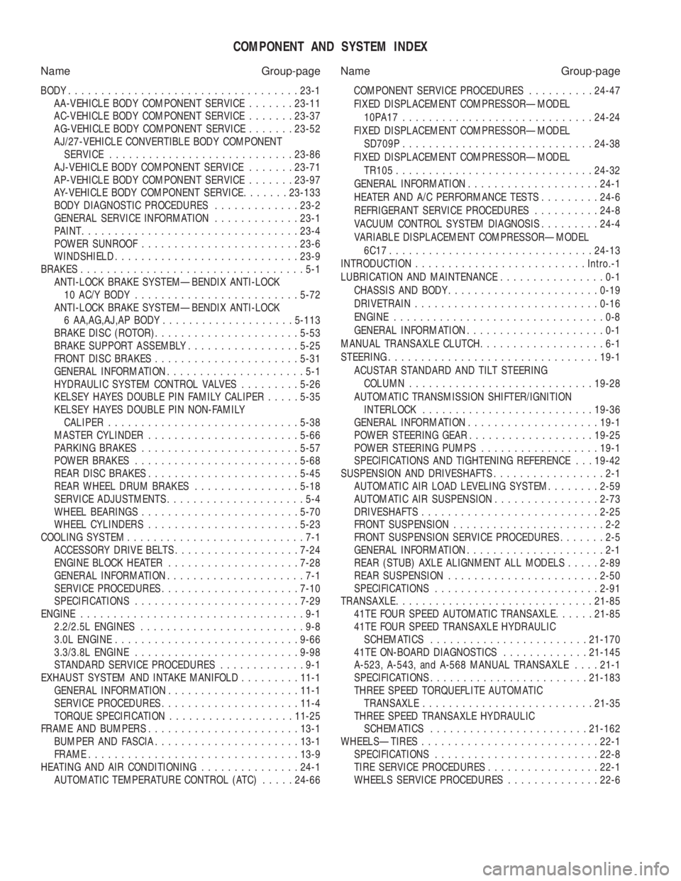
COMPONENT AND SYSTEM INDEX
Name Group-page Name Group-page
BODY ................................... 23-1
AA-VEHICLE BODY COMPONENT SERVICE .......23-11
AC-VEHICLE BODY COMPONENT SERVICE .......23-37
AG-VEHICLE BODY COMPONENT SERVICE .......23-52
AJ/27-VEHICLE CONVERTIBLE BODY COMPONENT SERVICE ............................ 23-86
AJ-VEHICLE BODY COMPONENT SERVICE .......23-71
AP-VEHICLE BODY COMPONENT SERVICE .......23-97
AY-VEHICLE BODY COMPONENT SERVICE .......23-133
BODY DIAGNOSTIC PROCEDURES .............23-2
GENERAL SERVICE INFORMATION .............23-1
PAINT ................................. 23-4
POWER SUNROOF ........................ 23-6
WINDSHIELD ............................ 23-9
BRAKES ..................................5-1
ANTI-LOCK BRAKE SYSTEMÐBENDIX ANTI-LOCK 10 AC/Y BODY ......................... 5-72
ANTI-LOCK BRAKE SYSTEMÐBENDIX ANTI-LOCK 6 AA,AG,AJ,AP BODY .................... 5-113
BRAKE DISC (ROTOR) ...................... 5-53
BRAKE SUPPORT ASSEMBLY .................5-25
FRONT DISC BRAKES ...................... 5-31
GENERAL INFORMATION .....................5-1
HYDRAULIC SYSTEM CONTROL VALVES .........5-26
KELSEY HAYES DOUBLE PIN FAMILY CALIPER .....5-35
KELSEY HAYES DOUBLE PIN NON-FAMILY CALIPER ............................. 5-38
MASTER CYLINDER ....................... 5-66
PARKING BRAKES ........................ 5-57
POWER BRAKES ......................... 5-68
REAR DISC BRAKES ....................... 5-45
REAR WHEEL DRUM BRAKES ................5-18
SERVICE ADJUSTMENTS .....................5-4
WHEEL BEARINGS ........................ 5-70
WHEEL CYLINDERS ....................... 5-23
COOLING SYSTEM ...........................7-1
ACCESSORY DRIVE BELTS ................... 7-24
ENGINE BLOCK HEATER .................... 7-28
GENERAL INFORMATION .....................7-1
SERVICE PROCEDURES ..................... 7-10
SPECIFICATIONS ......................... 7-29
ENGINE ..................................9-1
2.2/2.5L ENGINES .........................9-8
3.0L ENGINE ............................ 9-66
3.3/3.8L ENGINE ......................... 9-98
STANDARD SERVICE PROCEDURES .............9-1
EXHAUST SYSTEM AND INTAKE MANIFOLD .........11-1
GENERAL INFORMATION .................... 11-1
SERVICE PROCEDURES ..................... 11-4
TORQUE SPECIFICATION ................... 11-25
FRAME AND BUMPERS ....................... 13-1
BUMPER AND FASCIA ...................... 13-1
FRAME ................................ 13-9
HEATING AND AIR CONDITIONING ...............24-1
AUTOMATIC TEMPERATURE CONTROL (ATC) .....24-66 COMPONENT SERVICE PROCEDURES
..........24-47
FIXED DISPLACEMENT COMPRESSORÐMODEL 10PA17............................. 24-24
FIXED DISPLACEMENT COMPRESSORÐMODEL SD709P ............................. 24-38
FIXED DISPLACEMENT COMPRESSORÐMODEL TR105 .............................. 24-32
GENERAL INFORMATION .................... 24-1
HEATER AND A/C PERFORMANCE TESTS .........24-6
REFRIGERANT SERVICE PROCEDURES ..........24-8
VACUUM CONTROL SYSTEM DIAGNOSIS .........24-4
VARIABLE DISPLACEMENT COMPRESSORÐMODEL 6C17 ............................... 24-13
INTRODUCTION .......................... Intro.-1
LUBRICATION AND MAINTENANCE ................0-1
CHASSIS AND BODY ....................... 0-19
DRIVETRAIN ............................ 0-16
ENGINE ................................0-8
GENERAL INFORMATION .....................0-1
MANUAL TRANSAXLE CLUTCH ...................6-1
STEERING ................................ 19-1
ACUSTAR STANDARD AND TILT STEERING COLUMN ............................ 19-28
AUTOMATIC TRANSMISSION SHIFTER/IGNITION INTERLOCK .......................... 19-36
GENERAL INFORMATION .................... 19-1
POWER STEERING GEAR ................... 19-25
POWER STEERING PUMPS ..................19-1
SPECIFICATIONS AND TIGHTENING REFERENCE . . . 19-42
SUSPENSION AND DRIVESHAFTS .................2-1
AUTOMATIC AIR LOAD LEVELING SYSTEM ........2-59
AUTOMATIC AIR SUSPENSION ................2-73
DRIVESHAFTS ........................... 2-25
FRONT SUSPENSION .......................2-2
FRONT SUSPENSION SERVICE PROCEDURES .......2-5
GENERAL INFORMATION .....................2-1
REAR (STUB) AXLE ALIGNMENT ALL MODELS .....2-89
REAR SUSPENSION ....................... 2-50
SPECIFICATIONS ......................... 2-91
TRANSAXLE .............................. 21-85
41TE FOUR SPEED AUTOMATIC TRANSAXLE ......21-85
41TE FOUR SPEED TRANSAXLE HYDRAULIC SCHEMATICS ........................ 21-170
41TE ON-BOARD DIAGNOSTICS .............21-145
A-523, A-543, and A-568 MANUAL TRANSAXLE ....21-1
SPECIFICATIONS ........................ 21-183
THREE SPEED TORQUEFLITE AUTOMATIC TRANSAXLE .......................... 21-35
THREE SPEED TRANSAXLE HYDRAULIC SCHEMATICS ........................ 21-162
WHEELSÐTIRES ........................... 22-1
SPECIFICATIONS ......................... 22-8
TIRE SERVICE PROCEDURES .................22-1
WHEELS SERVICE PROCEDURES ..............22-6
Page 40 of 2438

LUBRICANTS AND GREASES
Lubricating grease is rated for quality and usage
by the NLGI. All approved products have the NLGI
symbol on the label. At the bottom NLGI symbol is the usage and qual-
ity identification letters. Wheel bearing lubricant is
identified by the letter ``G''. Chassis lubricant is iden-
tified by the letter ``L''. The letter following the us-
age letter indicates the quality of the lubricant. The
following symbols indicate the highest quality.
FLUID CAPACITIES
Fuel Tank
AP,AG and AJ ......................................53 L (14 gal.)
AA,AC and AY .....................................60 L (16 gal.)
AA-Flexible Fuel ..................................68 L (18 gal.)
Engine Oil
All.........................................................3.8 L (4.5 qts.)
Cooling System
2.2L ......................................................8.5 L (9.0 qts.)
2.5L ......................................................8.5 L (9.0 qts.)
3.0L ......................................................9.0 L (9.5 qts.)
3.3L ......................................................9.0 L (9.5 qts.)
3.8L ......................................................9.0 L (9.5 qts.)
Includes heater and coolant recovery bottle
Automatic Transaxle
Estimated Service Fill
ALL ......................................................3.8 L (4.0 qts.)
Overhaul Fill Capacity with Torque Converter
Empty
3-speed Fleet .......................................8.7 L (9.2 qts.)
3-speed .................................................8.2 L (8.8 qts.)
4-speed Electronic ................................9.4L (9.9 qts.)
Manual Transaxle
All ..........................................................9.4L (9.9 qts.)
Fill to bottom of fill hole.
Power Steering
All ...........................................................75L (1.5 pts.)
PARTS REQUIRING NO LUBRICATION
Many components on a Chrysler Corporation vehi-
cle require no periodic maintenance. Some compo-
nents are sealed and permanently lubricated. Rubber
bushings can deteriorate or limit damping ability if
lubricated. The following list of components require
no lubrication: ²
Air Pump
² Generator Bushings
² Drive Belts
² Drive Belt Idler/Tensioner Pulley
² Front Wheel Bearings
² Rubber Bushings
² Starter Bearings/Bushings
² Suspension Strut Bearings
² Throttle Control Cable
² Throttle Linkage
² Water Pump Bearings
JUMP STARTING PROCEDURE
WARNING: REVIEW ALL SAFETY PRECAUTIONS
AND WARNINGS IN GROUP 8A, BATTERY/START-
ING/CHARGING SYSTEMS DIAGNOSTICS. DO NOT JUMP START A FROZEN BATTERY, PER-
SONAL INJURY CAN RESULT. DO NOT JUMP START WHEN BATTERY INDICA-
TOR DOT IS YELLOW OR BRIGHT COLOR. DO NOT ALLOW JUMPER CABLE CLAMPS TO
TOUCH EACH OTHER WHEN CONNECTED TO A
BOOSTER SOURCE. DO NOT USE OPEN FLAME NEAR BATTERY.
REMOVE METALLIC JEWELRY WORN ON HANDS
OR WRISTS TO AVOID INJURY BY ACCIDENTAL
ARCHING OF BATTERY CURRENT. WHEN USING A HIGH OUTPUT BOOSTING DE-
VICE, DO NOT ALLOW BATTERY VOLTAGE TO EX-
CEED 16 VOLTS. REFER TO INSTRUCTIONS
PROVIDED WITH DEVICE BEING USED.
CAUTION: When using another vehicle as a
booster, do not allow vehicles to touch. Electrical
systems can be damaged on either vehicle.
TO JUMP START A DISABLED VEHICLE:
(1) Raise hood on disabled vehicle and visually in-
spect engine compartment for:
² Battery cable clamp condition, clean if necessary.
² Frozen battery.
² Yellow or bright color test indicator, if equipped.
² Low battery fluid level.
² Generator drive belt condition and tension.
² Fuel fumes or leakage, correct if necessary.
CAUTION: If the cause of starting problem on dis-
abled vehicle is severe, damage to booster vehicle
charging system can result.
(2) When using another vehicle as a booster
source, turn off all accessories, place gear selector in
park or neutral, set park brake and operate engine
at 1200 rpm.
NLGI SYMBOL
0 - 4 LUBRICATION AND MAINTENANCE Ä
Page 57 of 2438
flakes are visible in the used lubricant or the bearing
rollers and race cup is discolored, the bearing and
race cup should be replaced. For proper service pro-
cedures, see Group 5, Brakes. Replace the inner seal
whenever the wheel bearings are serviced.
REAR WHEEL BEARING LUBRICATION
CAUTION: Combining two types of lubricant can
cause bearing failure. Wash used or new bearings
with a suitable solvent and blot dry with a lint free
cloth before packing with new lubricant.
WARNING: DO NOT ALLOW BEARING TO SPIN AT
HIGH RPM WHEN USING COMPRESSED AIR TO
BLOW CLEANING SOLVENT FROM BEARING.
BEARING CAGE CAN EXPLODE, CAUSING PER-
SONAL INJURY.
TO LUBRICATE REAR WHEEL BEARINGS:
(1) Hoist rear wheels off the ground and support ve-
hicle on safety stands. Refer to Hoisting Recommenda-
tions in the General Information section of this group.
(2) Remove rear wheels.
(3) Remove brake caliper on vehicles with rear disc
brakes. For proper procedure, see Group 5, Brakes. (4) Remove rear wheel hub (drum) assembly and
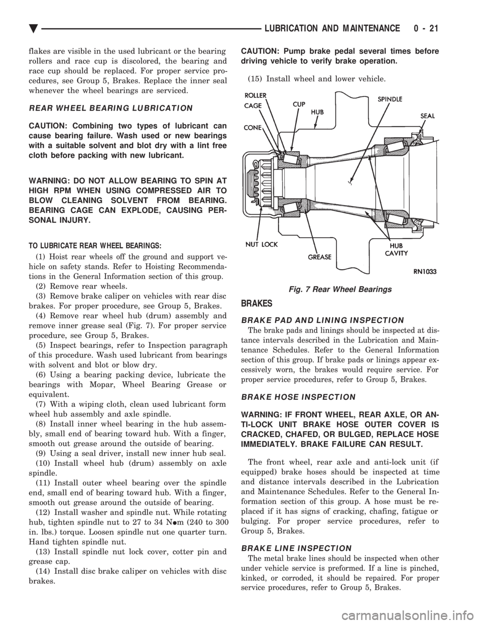
remove inner grease seal (Fig. 7). For proper service
procedure, see Group 5, Brakes. (5) Inspect bearings, refer to Inspection paragraph
of this procedure. Wash used lubricant from bearings
with solvent and blot or blow dry. (6) Using a bearing packing device, lubricate the
bearings with Mopar, Wheel Bearing Grease or
equivalent. (7) With a wiping cloth, clean used lubricant form
wheel hub assembly and axle spindle. (8) Install inner wheel bearing in the hub assem-
bly, small end of bearing toward hub. With a finger,
smooth out grease around the outside of bearing. (9) Using a seal driver, install new inner hub seal.
(10) Install wheel hub (drum) assembly on axle
spindle. (11) Install outer wheel bearing over the spindle
end, small end of bearing toward hub. With a finger,
smooth out grease around the outside of bearing. (12) Install washer and spindle nut. While rotating
hub, tighten spindle nut to 27 to 34 N Im (240 to 300
in. lbs.) torque. Loosen spindle nut one quarter turn.
Hand tighten spindle nut. (13) Install spindle nut lock cover, cotter pin and
grease cap. (14) Install disc brake caliper on vehicles with disc
brakes. CAUTION: Pump brake pedal several times before
driving vehicle to verify brake operation.
(15) Install wheel and lower vehicle.
BRAKES
BRAKE PAD AND LINING INSPECTION
The brake pads and linings should be inspected at dis-
tance intervals described in the Lubrication and Main-
tenance Schedules. Refer to the General Information
section of this group. If brake pads or linings appear ex-
cessively worn, the brakes would require service. For
proper service procedures, refer to Group 5, Brakes.
BRAKE HOSE INSPECTION
WARNING: IF FRONT WHEEL, REAR AXLE, OR AN-
TI-LOCK UNIT BRAKE HOSE OUTER COVER IS
CRACKED, CHAFED, OR BULGED, REPLACE HOSE
IMMEDIATELY. BRAKE FAILURE CAN RESULT.
The front wheel, rear axle and anti-lock unit (if
equipped) brake hoses should be inspected at time
and distance intervals described in the Lubrication
and Maintenance Schedules. Refer to the General In-
formation section of this group. A hose must be re-
placed if it has signs of cracking, chafing, fatigue or
bulging. For proper service procedures, refer to
Group 5, Brakes.
BRAKE LINE INSPECTION
The metal brake lines should be inspected when other
under vehicle service is preformed. If a line is pinched,
kinked, or corroded, it should be repaired. For proper
service procedures, refer to Group 5, Brakes.
Fig. 7 Rear Wheel Bearings
Ä LUBRICATION AND MAINTENANCE 0 - 21
Page 65 of 2438
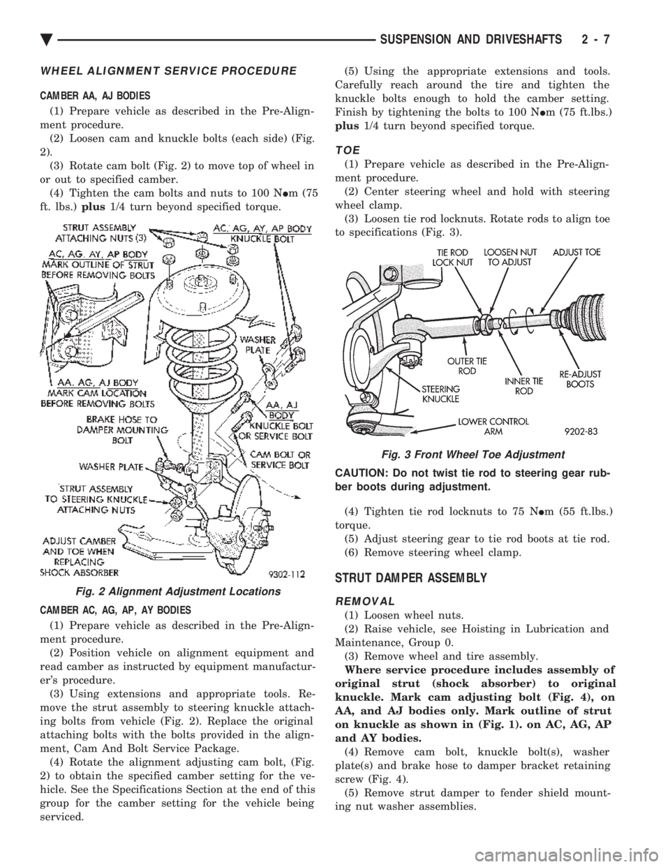
WHEEL ALIGNMENT SERVICE PROCEDURE
CAMBER AA, AJ BODIES (1) Prepare vehicle as described in the Pre-Align-
ment procedure. (2) Loosen cam and knuckle bolts (each side) (Fig.
2). (3) Rotate cam bolt (Fig. 2) to move top of wheel in
or out to specified camber. (4) Tighten the cam bolts and nuts to 100 N Im (75
ft. lbs.) plus1/4 turn beyond specified torque.
CAMBER AC, AG, AP, AY BODIES (1) Prepare vehicle as described in the Pre-Align-
ment procedure. (2) Position vehicle on alignment equipment and
read camber as instructed by equipment manufactur-
er's procedure. (3) Using extensions and appropriate tools. Re-
move the strut assembly to steering knuckle attach-
ing bolts from vehicle (Fig. 2). Replace the original
attaching bolts with the bolts provided in the align-
ment, Cam And Bolt Service Package. (4) Rotate the alignment adjusting cam bolt, (Fig.
2) to obtain the specified camber setting for the ve-
hicle. See the Specifications Section at the end of this
group for the camber setting for the vehicle being
serviced. (5) Using the appropriate extensions and tools.
Carefully reach around the tire and tighten the
knuckle bolts enough to hold the camber setting.
Finish by tightening the bolts to 100 N Im (75 ft.lbs.)
plus 1/4 turn beyond specified torque.
TOE
(1) Prepare vehicle as described in the Pre-Align-
ment procedure. (2) Center steering wheel and hold with steering
wheel clamp. (3) Loosen tie rod locknuts. Rotate rods to align toe
to specifications (Fig. 3).
CAUTION: Do not twist tie rod to steering gear rub-
ber boots during adjustment. (4) Tighten tie rod locknuts to 75 N Im (55 ft.lbs.)
torque. (5) Adjust steering gear to tie rod boots at tie rod.
(6) Remove steering wheel clamp.
STRUT DAMPER ASSEMBLY
REMOVAL
(1) Loosen wheel nuts.
(2) Raise vehicle, see Hoisting in Lubrication and
Maintenance, Group 0. (3) Remove wheel and tire assembly.
Where service procedure includes assembly of
original strut (shock absorber) to original
knuckle. Mark cam adjusting bolt (Fig. 4), on
AA, and AJ bodies only. Mark outline of strut
on knuckle as shown in (Fig. 1). on AC, AG, AP
and AY bodies. (4) Remove cam bolt, knuckle bolt(s), washer
plate(s) and brake hose to damper bracket retaining
screw (Fig. 4). (5) Remove strut damper to fender shield mount-
ing nut washer assemblies.
Fig. 2 Alignment Adjustment Locations
Fig. 3 Front Wheel Toe Adjustment
Ä SUSPENSION AND DRIVESHAFTS 2 - 7
Page 66 of 2438
INSPECTION
Inspect for evidence of fluid running from the up-
per end of the reservoir. (Actual leakage will be a
stream of fluid running down the side and dripping
off lower end of unit). A slight amount of seepage be-
tween the strut rod and strut shaft seal is not un-
usual and does not affect performance of the strut
assembly.
INSTALLATION
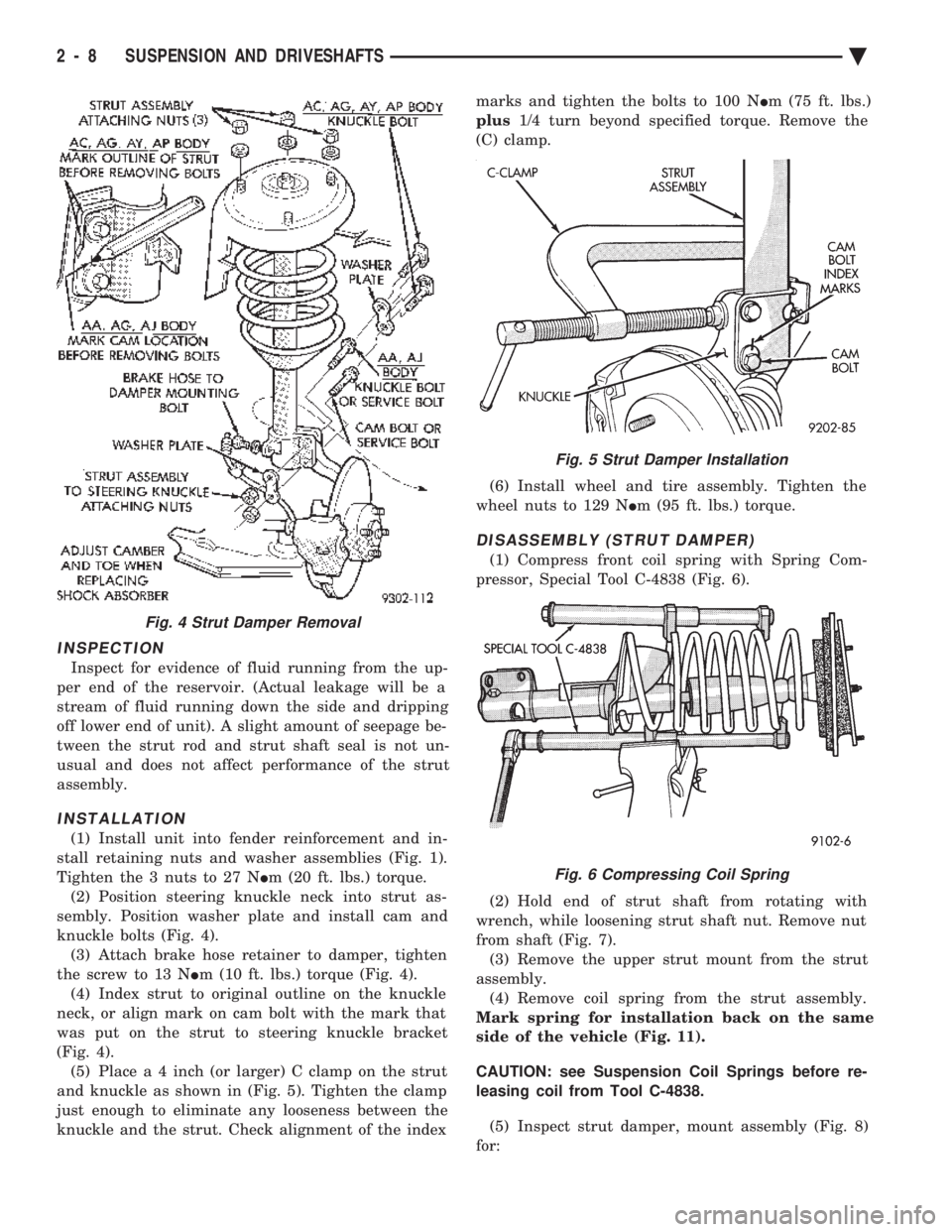
(1) Install unit into fender reinforcement and in-
stall retaining nuts and washer assemblies (Fig. 1).
Tighten the 3 nuts to 27 N Im (20 ft. lbs.) torque.
(2) Position steering knuckle neck into strut as-
sembly. Position washer plate and install cam and
knuckle bolts (Fig. 4). (3) Attach brake hose retainer to damper, tighten
the screw to 13 N Im (10 ft. lbs.) torque (Fig. 4).
(4) Index strut to original outline on the knuckle
neck, or align mark on cam bolt with the mark that
was put on the strut to steering knuckle bracket
(Fig. 4). (5) Plac e a 4 inch (or larger) C clamp on the strut
and knuckle as shown in (Fig. 5). Tighten the clamp
just enough to eliminate any looseness between the
knuckle and the strut. Check alignment of the index marks and tighten the bolts to 100 N
Im (75 ft. lbs.)
plus 1/4 turn beyond specified torque. Remove the
(C) clamp.
(6) Install wheel and tire assembly. Tighten the
wheel nuts to 129 N Im (95 ft. lbs.) torque.
DISASSEMBLY (STRUT DAMPER)
(1) Compress front coil spring with Spring Com-
pressor, Special Tool C-4838 (Fig. 6).
(2) Hold end of strut shaft from rotating with
wrench, while loosening strut shaft nut. Remove nut
from shaft (Fig. 7). (3) Remove the upper strut mount from the strut
assembly. (4) Remove coil spring from the strut assembly.
Mark spring for installation back on the same
side of the vehicle (Fig. 11).
CAUTION: see Suspension Coil Springs before re-
leasing coil from Tool C-4838.
(5) Inspect strut damper, mount assembly (Fig. 8)
for:
Fig. 4 Strut Damper Removal
Fig. 5 Strut Damper Installation
Fig. 6 Compressing Coil Spring
2 - 8 SUSPENSION AND DRIVESHAFTS Ä
Page 74 of 2438
the lower clamps and bolts. The center offset in the
sway bar should be oriented toward the front of the
vehicle (Fig. 16)(3) Position bushing retainers on lower control arms
and install bolts (Fig. 16). (4) With lower control arms raised to design height,
tighten all retainer attaching bolts to 70 N Im (50 ft.
lbs.) torque. (5) Lower vehicle.
KNUCKLE (FRONT SUSPENSION)
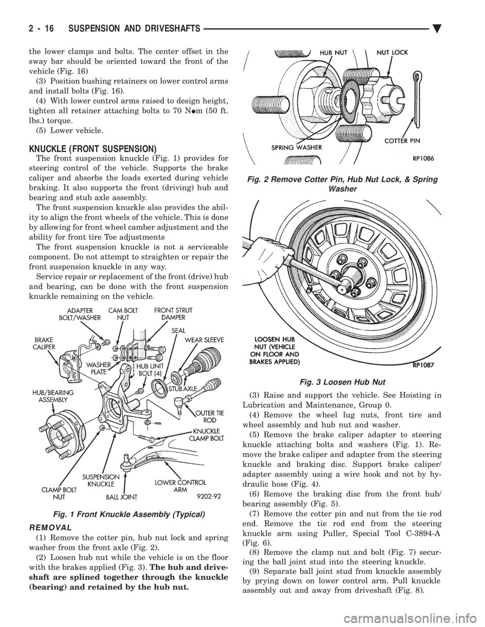
The front suspension knuckle (Fig. 1) provides for
steering control of the vehicle. Supports the brake
caliper and absorbs the loads exerted during vehicle
braking. It also supports the front (driving) hub and
bearing and stub axle assembly. The front suspension knuckle also provides the abil-
ity to align the front wheels of the vehicle. This is done
by allowing for front wheel camber adjustment and the
ability for front tire Toe adjustments The front suspension knuckle is not a serviceable
component. Do not attempt to straighten or repair the
front suspension knuckle in any way. Service repair or replacement of the front (drive) hub
and bearing, can be done with the front suspension
knuckle remaining on the vehicle.
REMOVAL
(1) Remove the cotter pin, hub nut lock and spring
washer from the front axle (Fig. 2). (2) Loosen hub nut while the vehicle is on the floor
with the brakes applied (Fig. 3). The hub and drive-
shaft are splined together through the knuckle
(bearing) and retained by the hub nut. (3) Raise and support the vehicle. See Hoisting in
Lubrication and Maintenance, Group 0. (4) Remove the wheel lug nuts, front tire and
wheel assembly and hub nut and washer. (5) Remove the brake caliper adapter to steering
knuckle attaching bolts and washers (Fig. 1). Re-
move the brake caliper and adapter from the steering
knuckle and braking disc. Support brake caliper/
adapter assembly using a wire hook and not by hy-
draulic hose (Fig. 4). (6) Remove the braking disc from the front hub/
bearing assembly (Fig. 5). (7) Remove the cotter pin and nut from the tie rod
end. Remove the tie rod end from the steering
knuckle arm using Puller, Special Tool C-3894-A
(Fig. 6). (8) Remove the clamp nut and bolt (Fig. 7) secur-
ing the ball joint stud into the steering knuckle. (9) Separate ball joint stud from knuckle assembly
by prying down on lower control arm. Pull knuckle
assembly out and away from driveshaft (Fig. 8).
Fig. 2 Remove Cotter Pin, Hub Nut Lock, & Spring Washer
Fig. 3 Loosen Hub Nut
Fig. 1 Front Knuckle Assembly (Typical)
2 - 16 SUSPENSION AND DRIVESHAFTS Ä
Page 77 of 2438
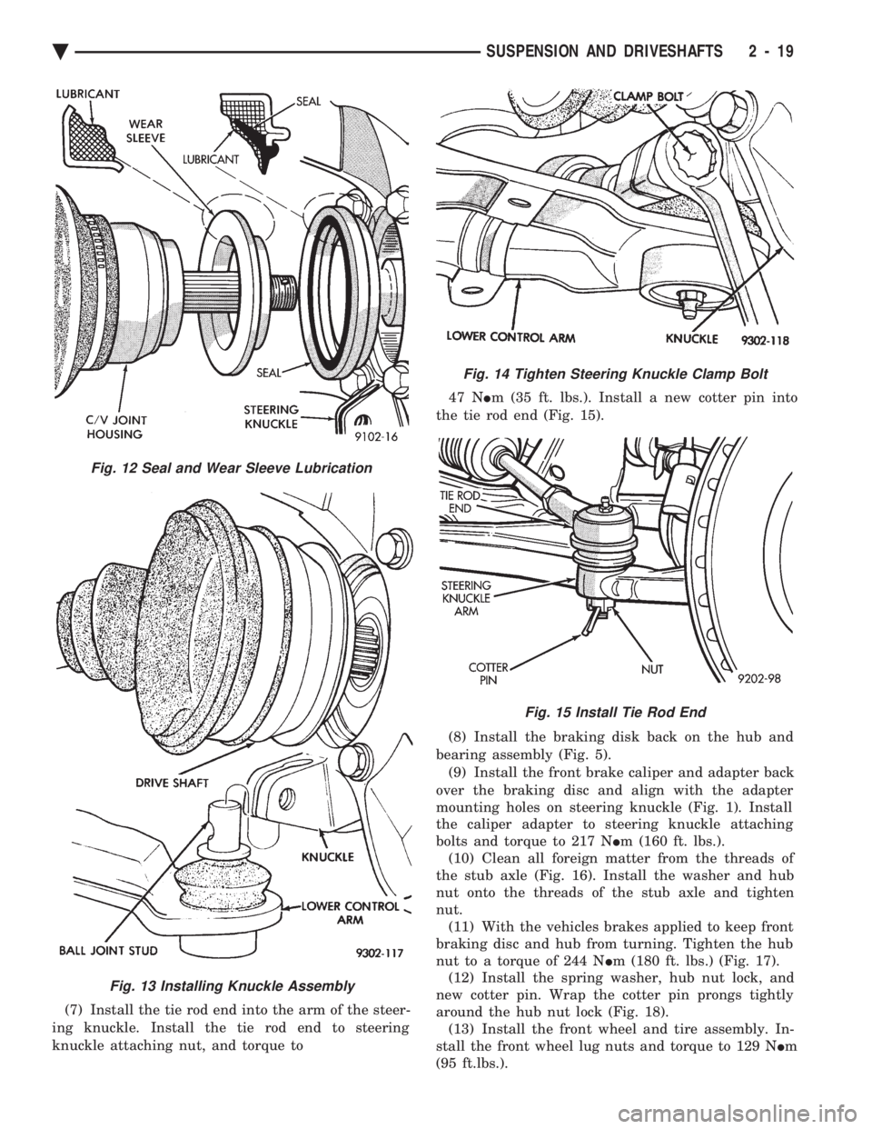
(7) Install the tie rod end into the arm of the steer-
ing knuckle. Install the tie rod end to steering
knuckle attaching nut, and torque to 47 N
Im (35 ft. lbs.). Install a new cotter pin into
the tie rod end (Fig. 15).
(8) Install the braking disk back on the hub and
bearing assembly (Fig. 5). (9) Install the front brake caliper and adapter back
over the braking disc and align with the adapter
mounting holes on steering knuckle (Fig. 1). Install
the caliper adapter to steering knuckle attaching
bolts and torque to 217 N Im (160 ft. lbs.).
(10) Clean all foreign matter from the threads of
the stub axle (Fig. 16). Install the washer and hub
nut onto the threads of the stub axle and tighten
nut. (11) With the vehicles brakes applied to keep front
braking disc and hub from turning. Tighten the hub
nut to a torque of 244 N Im (180 ft. lbs.) (Fig. 17).
(12) Install the spring washer, hub nut lock, and
new cotter pin. Wrap the cotter pin prongs tightly
around the hub nut lock (Fig. 18). (13) Install the front wheel and tire assembly. In-
stall the front wheel lug nuts and torque to 129 N Im
(95 ft.lbs.).
Fig. 13 Installing Knuckle Assembly
Fig. 12 Seal and Wear Sleeve Lubrication
Fig. 14 Tighten Steering Knuckle Clamp Bolt
Fig. 15 Install Tie Rod End
Ä SUSPENSION AND DRIVESHAFTS 2 - 19
Page 82 of 2438
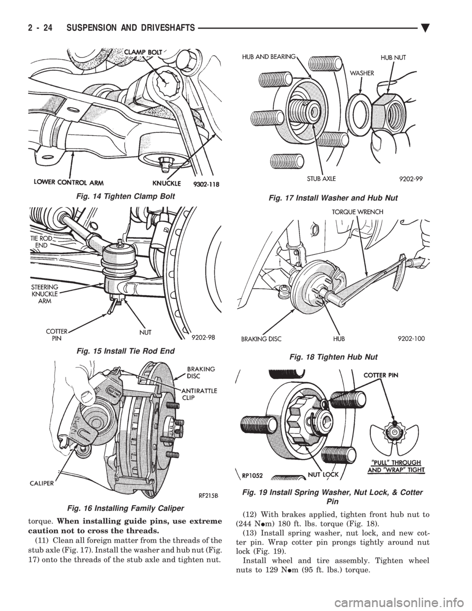
torque. When installing guide pins, use extreme
caution not to cross the threads. (11) Clean all foreign matter from the threads of the
stub axle (Fig. 17). Install the washer and hub nut (Fig.
17) onto the threads of the stub axle and tighten nut. (12) With brakes applied, tighten front hub nut to
(244 N Im) 180 ft. lbs. torque (Fig. 18).
(13) Install spring washer, nut lock, and new cot-
ter pin. Wrap cotter pin prongs tightly around nut
lock (Fig. 19). Install wheel and tire assembly. Tighten wheel
nuts to 129 N Im (95 ft. lbs.) torque.
Fig. 15 Install Tie Rod End
Fig. 16 Installing Family Caliper
Fig. 17 Install Washer and Hub Nut
Fig. 18 Tighten Hub Nut
Fig. 19 Install Spring Washer, Nut Lock, & Cotter
Pin
Fig. 14 Tighten Clamp Bolt
2 - 24 SUSPENSION AND DRIVESHAFTS Ä