fuel tank removal CHEVROLET DYNASTY 1993 User Guide
[x] Cancel search | Manufacturer: CHEVROLET, Model Year: 1993, Model line: DYNASTY, Model: CHEVROLET DYNASTY 1993Pages: 2438, PDF Size: 74.98 MB
Page 1751 of 2438
fuel tube enters the fitting, the retainer locks the shoul-
der of the nipple in place and the O-rings seal the tube.
CAUTION: Quick-connect fittings are not serviced
separately. Do not attempt to repair damaged quick-
connect fittings or fuel tubes. Replace the complete
fuel tube/quick-connect fitting assembly.
When installing fuel tubes, route them in the holders
along the frame rail, fuel tank and the rear of the en-
gine.
REMOVAL
WARNING: RELEASE FUEL SYSTEM PRESSURE
BEFORE SERVICING FUEL SYSTEM COMPONENTS.
WHEN SERVICING FLEXIBLE FUEL VEHICLES,
WEAR METHANOL RESISTANT GLOVES AND EYE
PROTECTION AND AVOID BREATHING FUMES. DO
NOT ALLOW METHANOL/GASOLINE MIXTURES TO
CONTACT SKIN. SERVICE VEHICLES IN WELL VEN-
TILATED AREAS AND AVOID IGNITION SOURCES.
NEVER SMOKE WHILE SERVICING THE VEHICLE.
(1) Disconnect negative cable from the battery.
(2) Perform the Fuel Pressure Release Procedure.
Refer to the Fuel Pressure Release Procedure in this
section. (3) Remove any loose dirt from quick connect fit-
tings.
WARNING: WRAP SHOP TOWELS AROUND HOSES
TO CATCH ANY FUEL SPILLAGE.
(4) Push the quick connect fitting toward the fuel
tube while depressing the built-in release tool. Then
slightly twist the fitting and pull it off the fuel tube
(Fig. 14). (5) Cover the fitting to prevent contamination.
TUBE/FITTING SERVICE
WARNING: RELEASE FUEL SYSTEM PRESSURE
BEFORE SERVICING FUEL SYSTEM COMPONENTS.
WHEN SERVICING FLEXIBLE FUEL VEHICLES,
WEAR METHANOL RESISTANT GLOVES AND EYE
PROTECTION AND AVOID BREATHING FUMES. DO
NOT ALLOW METHANOL/GASOLINE MIXTURES TO
CONTACT SKIN. SERVICE VEHICLES IN WELL VEN-
TILATED AREAS AND AVOID IGNITION SOURCES.
NEVER SMOKE WHILE SERVICING THE VEHICLE.
If a quick connect fitting needs service, the follow-
ing procedure must be followed: (1) Disconnect the battery negative battery cable.
(2) Perform the Fuel System Pressure Release Pro-
cedure.
WARNING: WRAP SHOP TOWELS AROUND HOSES
TO CATCH ANY FUEL SPILLAGE. (3) Remove the quick connect fitting from the fuel
tube by pushing in on the plastic ring located on the
end of the fitting. Gently pull the fitting from the
fuel tube. (4) Cut off the crimp ferrules at each end of the
hose, taking care not to damage the quick connect
fitting or the fuel tube. (5) Discard the ferrules and hose.
WARNING: FUEL SYSTEM HOSES AND TUBES DE-
SIGNED FOR GASOLINE ONLY VEHICLES CANNOT
BE USED ON FLEXIBLE FUEL VEHICLES. WHEN
SERVICING THE FUEL SYSTEM OF A FLEXIBLE
FUEL VEHICLE, ONLY USE ORIGINAL EQUIPMENT
OR EQUIVALENT REPLACEMENT COMPONENTS.
(6) Replace the hose using original equipment or
equivalent hose. (7) Attach the replacement hose to the quick con-
nect fitting and fuel tube using the correct hose
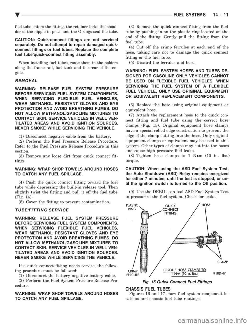
clamps (Fig. 15). Original equipment hose clamps
have a special rolled edge construction to prevent the
edge of the clamp cutting into the hose. Only original
equipment clamps or equivalent may be used in this
system. Other types of clamps may cut into the hoses
and cause high pressure fuel leaks. (8) Tighten hose clamps to 1 N Im (10 in. lbs.)
torque.
CAUTION: When using the ASD Fuel System Test,
the Auto Shutdown (ASD) Relay remains energized
for either 7 minutes, until the test is stopped, or un-
til the ignition switch is turned to the Off position.
(9) Use the DRBII scan tool ASD Fuel System Test
to pressurize the fuel system. Check for leaks.
CHASSIS FUEL TUBES
Figures 16 and 17 show fuel system component lo-
cations and chassis fuel tube routings.
Fig. 15 Quick Connect Fuel Fittings
Ä FUEL SYSTEMS 14 - 11
Page 1756 of 2438
jector terminal in the harness connector. Repeat pro-
cedure for 2 to 3 injectors.
FUEL TANK
DRAINING FUEL TANK
WARNING: RELEASE FUEL SYSTEM PRESSURE
BEFORE SERVICING FUEL SYSTEM COMPONENTS.
WHEN SERVICING FLEXIBLE FUEL VEHICLES,
WEAR METHANOL RESISTANT GLOVES AND EYE
PROTECTION AND AVOID BREATHING FUMES. DO
NOT ALLOW METHANOL/GASOLINE MIXTURES TO
CONTACT SKIN. SERVICE VEHICLES IN WELL VEN-
TILATED AREAS AND AVOID IGNITION SOURCES.
NEVER SMOKE WHILE SERVICING THE VEHICLE.
(1) Remove fuel filler cap.
(2) Perform the Fuel System Pressure Release pro-
cedure. (3) Remove ground cable from battery.
(4) Raise vehicle on hoist.
(5) Remove rubber cap from drain tube. The tube
is located on rear of fuel tank. Connect either a por-
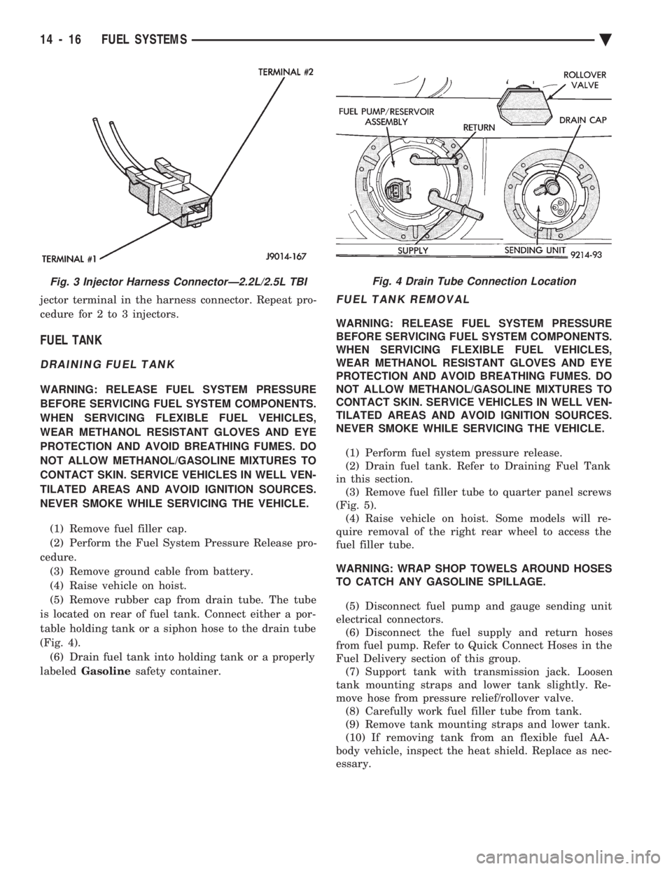
table holding tank or a siphon hose to the drain tube
(Fig. 4). (6) Drain fuel tank into holding tank or a properly
labeled Gasoline safety container.
FUEL TANK REMOVAL
WARNING: RELEASE FUEL SYSTEM PRESSURE
BEFORE SERVICING FUEL SYSTEM COMPONENTS.
WHEN SERVICING FLEXIBLE FUEL VEHICLES,
WEAR METHANOL RESISTANT GLOVES AND EYE
PROTECTION AND AVOID BREATHING FUMES. DO
NOT ALLOW METHANOL/GASOLINE MIXTURES TO
CONTACT SKIN. SERVICE VEHICLES IN WELL VEN-
TILATED AREAS AND AVOID IGNITION SOURCES.
NEVER SMOKE WHILE SERVICING THE VEHICLE.
(1) Perform fuel system pressure release.
(2) Drain fuel tank. Refer to Draining Fuel Tank
in this section. (3) Remove fuel filler tube to quarter panel screws
(Fig. 5). (4) Raise vehicle on hoist. Some models will re-
quire removal of the right rear wheel to access the
fuel filler tube.
WARNING: WRAP SHOP TOWELS AROUND HOSES
TO CATCH ANY GASOLINE SPILLAGE.
(5) Disconnect fuel pump and gauge sending unit
electrical connectors. (6) Disconnect the fuel supply and return hoses
from fuel pump. Refer to Quick Connect Hoses in the
Fuel Delivery section of this group. (7) Support tank with transmission jack. Loosen
tank mounting straps and lower tank slightly. Re-
move hose from pressure relief/rollover valve. (8) Carefully work fuel filler tube from tank.
(9) Remove tank mounting straps and lower tank.
(10) If removing tank from an flexible fuel AA-
body vehicle, inspect the heat shield. Replace as nec-
essary.
Fig. 3 Injector Harness ConnectorÐ2.2L/2.5L TBIFig. 4 Drain Tube Connection Location
14 - 16 FUEL SYSTEMS Ä
Page 1758 of 2438
INSTALLATION
WARNING: FUEL TANKS DESIGNED FOR GASO-
LINE ONLY VEHICLES CANNOT BE USED ON
FLEXIBLE FUEL AA-BODY VEHICLES. WHEN SER-
VICING THE FUEL SYSTEM OF A FLEXIBLE FUEL
VEHICLE, ONLY USE ORIGINAL EQUIPMENT OR
EQUIVALENT REPLACEMENT COMPONENTS. (1) Position fuel tank on transmission jack. Con-
nect vapor separator/rollover valve hose and position
insulator pad on fuel tank. Position vapor vent so
that it is not pinched between tank and floor pan
during installation. (2) Raise tank and fuel filler tube carefully into
position. Use a light coating of power steering fluid
to ease fuel filler tube installation. Ensure filler tube
grommet is not damaged. Verify that the tube is in-
stalled correctly. (3) Tighten fuel tank strap nuts to 23 N Im (250 in.
lbs.) torque. Remove transmission jack. Ensure
straps are not twisted or bent. (4) Lubricate the metal tubes on the fuel pump
with clean 30 weight engine oil. Install the quick
connect fuel fittings. Refer to Quick Connect Fittings
in the Fuel Delivery section of this Group. (5) Attach electrical connector to fuel pump mod-
ule and level sensor unit. (6) Lower the vehicle.
(7) Attach filler tube to filler neck opening in
quarter panel. Tighten quarter panel screws to 2
N Im (17 in. lbs.) torque.
(8) Fill fuel tank, install filler cap, and connect
battery cable.
CAUTION: When using the ASD Fuel System Test,
the Auto Shutdown (ASD) Relay remains energized
for either 7 minutes, until the test is stopped, or un-
til the ignition switch is turned to the Off position.
(9) Use the DRBII scan tool ASD Fuel System Test
to pressurize the fuel system. Check for leaks.
FUEL PUMP MODULE
Refer to the Fuel Delivery section of this group.
METHANOL CONCENTRATION SENSOR
Refer to the Fuel Delivery section of this group.
FUEL RESERVOIR
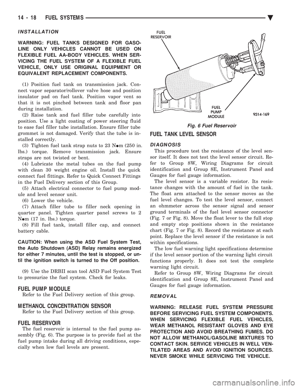
The fuel reservoir is internal to the fuel pump as-
sembly (Fig. 6). The purpose is to provide fuel at the
fuel pump intake during all driving conditions, espe-
cially when low fuel levels are present.
FUEL TANK LEVEL SENSOR
DIAGNOSIS
This procedure test the resistance of the level sen-
sor itself. It does not test the level sensor circuit. Re-
fer to Group 8W, Wiring Diagrams for circuit
identification and Group 8E, Instrument Panel and
Gauges for fuel gauge information. The level sensor is a variable resistor. Its resis-
tance changes with the amount of fuel in the tank.
The float arm attached to the sensor moves as the
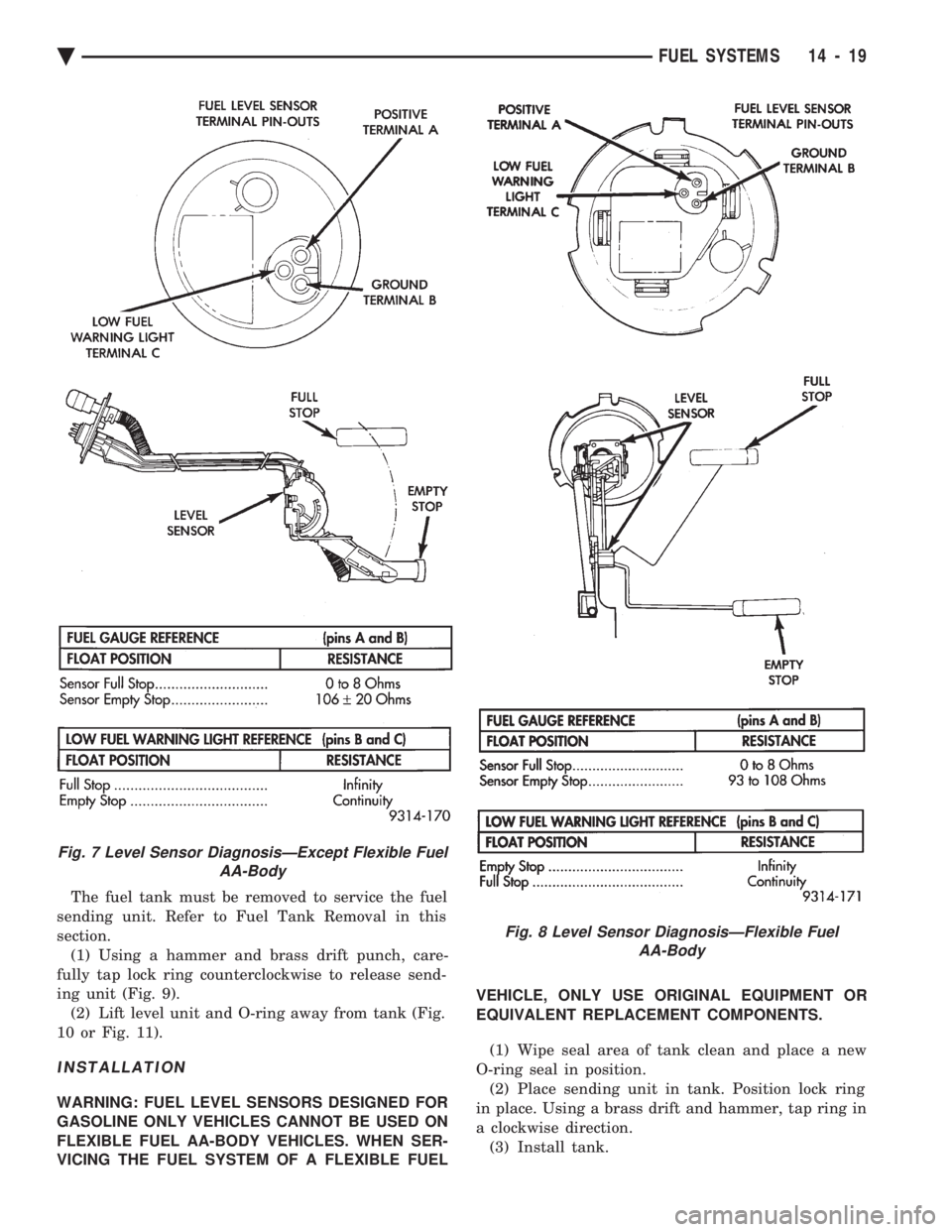
fuel level changes. To test the level sensor, connect
an ohmmeter across the sensor signal and sensor
ground terminals of the fuel level sensor connector
(Fig. 7 or Fig. 8). Move the float lever to the full stop
and empty stop positions shown in the resistance
chart (Fig. 7 or Fig. 8). Record the resistance at each
point. Replace the level sensor if the resistance is not
within specifications. The low fuel warning light specifications determine
if the level sensor portion of the warning light circuit
functions properly. It does not test the complete
warning light circuit. Refer to Group 8W, Wiring Diagrams for circuit
identification and Group 8E, Instrument Panel and
Gauges for fuel gauge information.
REMOVAL
WARNING: RELEASE FUEL SYSTEM PRESSURE
BEFORE SERVICING FUEL SYSTEM COMPONENTS.
WHEN SERVICING FLEXIBLE FUEL VEHICLES,
WEAR METHANOL RESISTANT GLOVES AND EYE
PROTECTION AND AVOID BREATHING FUMES. DO
NOT ALLOW METHANOL/GASOLINE MIXTURES TO
CONTACT SKIN. SERVICE VEHICLES IN WELL VEN-
TILATED AREAS AND AVOID IGNITION SOURCES.
NEVER SMOKE WHILE SERVICING THE VEHICLE.
Fig. 6 Fuel Reservoir
14 - 18 FUEL SYSTEMS Ä
Page 1759 of 2438
The fuel tank must be removed to service the fuel
sending unit. Refer to Fuel Tank Removal in this
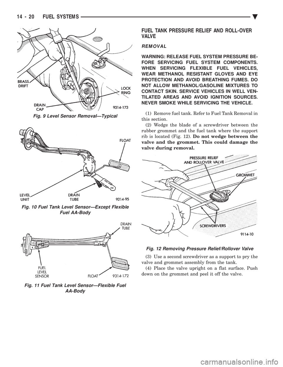
section. (1) Using a hammer and brass drift punch, care-
fully tap lock ring counterclockwise to release send-
ing unit (Fig. 9). (2) Lift level unit and O-ring away from tank (Fig.
10 or Fig. 11).
INSTALLATION
WARNING: FUEL LEVEL SENSORS DESIGNED FOR
GASOLINE ONLY VEHICLES CANNOT BE USED ON
FLEXIBLE FUEL AA-BODY VEHICLES. WHEN SER-
VICING THE FUEL SYSTEM OF A FLEXIBLE FUEL VEHICLE, ONLY USE ORIGINAL EQUIPMENT OR
EQUIVALENT REPLACEMENT COMPONENTS.
(1) Wipe seal area of tank clean and place a new
O-ring seal in position. (2) Place sending unit in tank. Position lock ring
in place. Using a brass drift and hammer, tap ring in
a clockwise direction. (3) Install tank.
Fig. 8 Level Sensor DiagnosisÐFlexible Fuel AA-Body
Fig. 7 Level Sensor DiagnosisÐExcept Flexible Fuel AA-Body
Ä FUEL SYSTEMS 14 - 19
Page 1760 of 2438
FUEL TANK PRESSURE RELIEF AND ROLL-OVER
VALVE
REMOVAL
WARNING: RELEASE FUEL SYSTEM PRESSURE BE-
FORE SERVICING FUEL SYSTEM COMPONENTS.
WHEN SERVICING FLEXIBLE FUEL VEHICLES,
WEAR METHANOL RESISTANT GLOVES AND EYE
PROTECTION AND AVOID BREATHING FUMES. DO
NOT ALLOW METHANOL/GASOLINE MIXTURES TO
CONTACT SKIN. SERVICE VEHICLES IN WELL VEN-
TILATED AREAS AND AVOID IGNITION SOURCES.
NEVER SMOKE WHILE SERVICING THE VEHICLE.
(1) Remove fuel tank. Refer to Fuel Tank Removal in
this section. (2) Wedge the blade of a screwdriver between the
rubber grommet and the fuel tank where the support
rib is located (Fig. 12). Do not wedge between the
valve and the grommet. This could damage the
valve during removal.
(3) Use a second screwdriver as a support to pry the
valve and grommet assembly from the tank. (4) Place the valve upright on a flat surface. Push
down on the grommet and peel it off the valve.
Fig. 9 Level Sensor RemovalÐTypical
Fig. 10 Fuel Tank Level SensorÐExcept Flexible Fuel AA-Body
Fig. 11 Fuel Tank Level SensorÐFlexible Fuel AA-Body
Fig. 12 Removing Pressure Relief/Rollover Valve
14 - 20 FUEL SYSTEMS Ä
Page 1761 of 2438
INSTALLATION
WARNING: FUEL PRESSURE RELIEF/ROLLOVER
VALVES DESIGNED FOR GASOLINE ONLY VEHI-
CLES CANNOT BE USED ON FLEXIBLE FUEL AA-
BODY VEHICLES. WHEN SERVICING THE FUEL
SYSTEM OF A FLEXIBLE FUEL VEHICLE, ONLY
USE ORIGINAL EQUIPMENT OR EQUIVALENT RE-
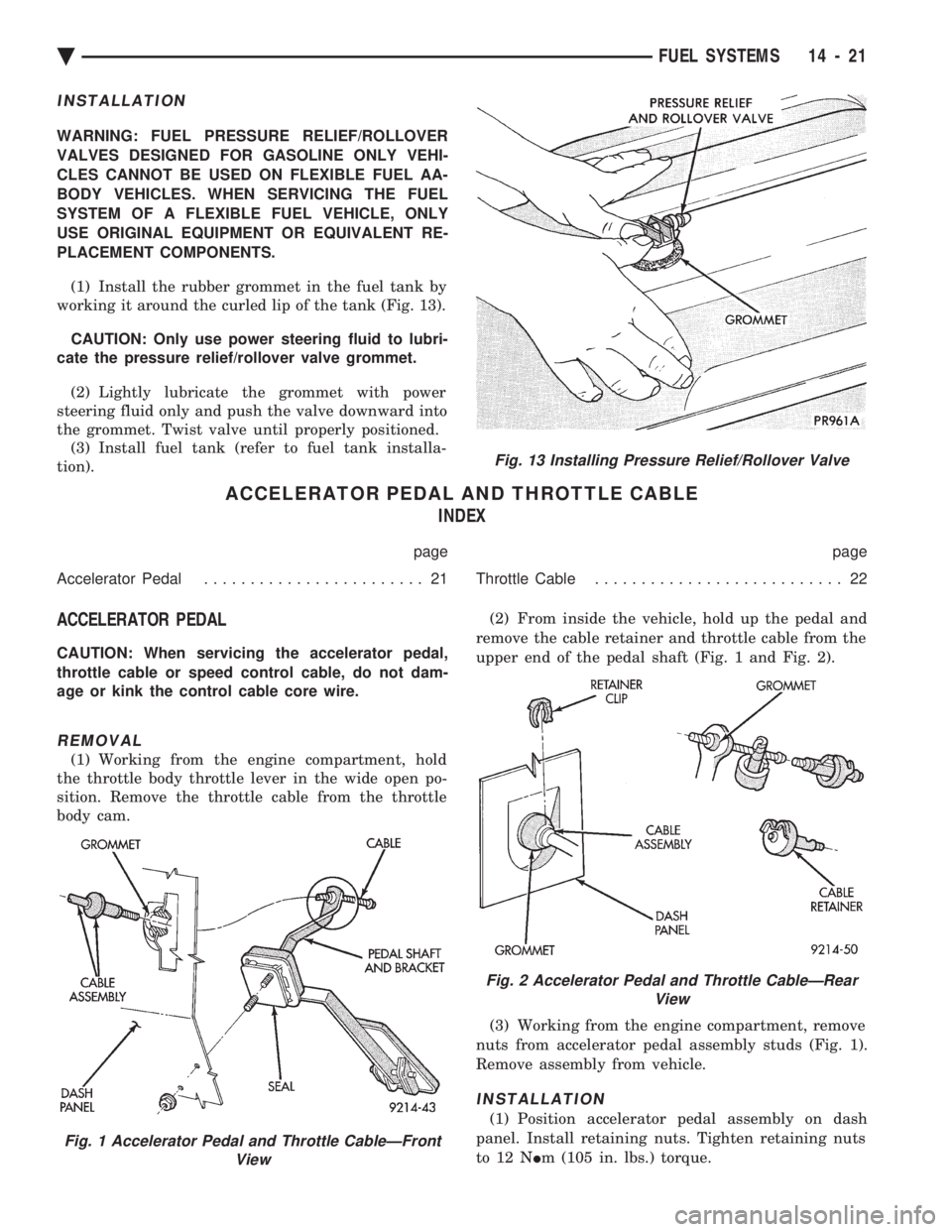
PLACEMENT COMPONENTS. (1) Install the rubber grommet in the fuel tank by
working it around the curled lip of the tank (Fig. 13).
CAUTION: Only use power steering fluid to lubri-
cate the pressure relief/rollover valve grommet.
(2) Lightly lubricate the grommet with power
steering fluid only and push the valve downward into
the grommet. Twist valve until properly positioned. (3) Install fuel tank (refer to fuel tank installa-
tion).
ACCELERATOR PEDAL AND THROTTLE CABLE INDEX
page page
Accelerator Pedal ........................ 21 Throttle Cable........................... 22
ACCELERATOR PEDAL
CAUTION: When servicing the accelerator pedal,
throttle cable or speed control cable, do not dam-
age or kink the control cable core wire.
REMOVAL
(1) Working from the engine compartment, hold
the throttle body throttle lever in the wide open po-
sition. Remove the throttle cable from the throttle
body cam. (2) From inside the vehicle, hold up the pedal and
remove the cable retainer and throttle cable from the
upper end of the pedal shaft (Fig. 1 and Fig. 2).
(3) Working from the engine compartment, remove
nuts from accelerator pedal assembly studs (Fig. 1).
Remove assembly from vehicle.
INSTALLATION
(1) Position accelerator pedal assembly on dash
panel. Install retaining nuts. Tighten retaining nuts
to 12 N Im (105 in. lbs.) torque.
Fig. 1 Accelerator Pedal and Throttle CableÐFront
View
Fig. 13 Installing Pressure Relief/Rollover Valve
Fig. 2 Accelerator Pedal and Throttle CableÐRearView
Ä FUEL SYSTEMS 14 - 21
Page 1788 of 2438
2.2L/2.5L SINGLE POINT FUEL INJECTIONÐSERVICE PROCEDURES INDEX
page page
Canister Purge Solenoid ................... 53
Electric Exhaust Gas Recirculation Transducer (EET) Service ............................... 53
Fuel Fitting ............................. 50
Fuel Injector ............................ 51
Fuel Lines and Hoses ..................... 48
Fuel Pressure Regulator ................... 51 Fuel System Pressure Release Procedure
...... 48
Heated Oxygen Sensor (O
2Sensor) .......... 54
Idle Air Control Motor ..................... 53
Manifold Absolute Pressure Sensor ........... 53
PCM Service ............................ 54
Throttle Body ............................ 48
Throttle Position Sensor ................... 52
FUEL LINES AND HOSES
Perform the Fuel System Pressure Relief Procedure
before servicing the fuel system. The procedure must
be done to bleed fuel pressure from the system before
removing clamps or hoses. Use care when removing fuel hoses to prevent dam-
age to hose or hose nipple. Always use new hose
clamps, of the correct type, during reassembly. Tighten
hose clamps to 1 N Im (10 in. lbs.) torque. Do not use
aviation style clamps on this system or hose
damage may result.
FUEL SYSTEM PRESSURE RELEASE PROCEDURE
CAUTION: Before servicing the fuel pump, fuel lines,
fuel filter, throttle body, or fuel injector, release fuel
system pressure.
(1) Loosen fuel filler cap to release fuel tank pres-
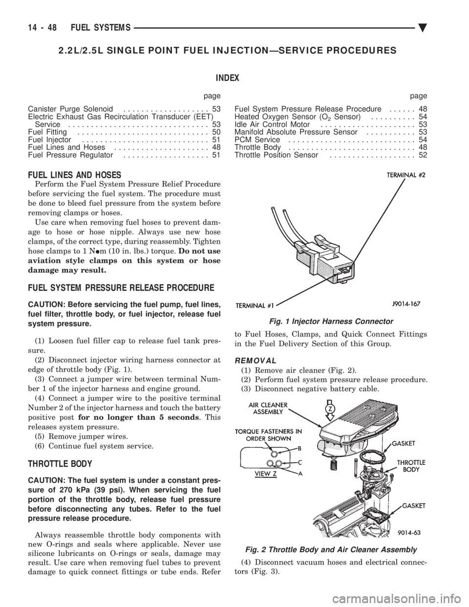
sure. (2) Disconnect injector wiring harness connector at
edge of throttle body (Fig. 1). (3) Connect a jumper wire between terminal Num-
ber 1 of the injector harness and engine ground. (4) Connect a jumper wire to the positive terminal
Number 2 of the injector harness and touch the battery
positive post for no longer than 5 seconds . This
releases system pressure. (5) Remove jumper wires.
(6) Continue fuel system service.
THROTTLE BODY
CAUTION: The fuel system is under a constant pres-
sure of 270 kPa (39 psi). When servicing the fuel
portion of the throttle body, release fuel pressure
before disconnecting any tubes. Refer to the fuel
pressure release procedure.
Always reassemble throttle body components with
new O-rings and seals where applicable. Never use
silicone lubricants on O-rings or seals, damage may
result. Use care when removing fuel tubes to prevent
damage to quick connect fittings or tube ends. Refer to Fuel Hoses, Clamps, and Quick Connect Fittings
in the Fuel Delivery Section of this Group.
REMOVAL
(1) Remove air cleaner (Fig. 2).
(2) Perform fuel system pressure release procedure.
(3) Disconnect negative battery cable.
(4) Disconnect vacuum hoses and electrical connec-
tors (Fig. 3).
Fig. 1 Injector Harness Connector
Fig. 2 Throttle Body and Air Cleaner Assembly
14 - 48 FUEL SYSTEMS Ä
Page 1795 of 2438
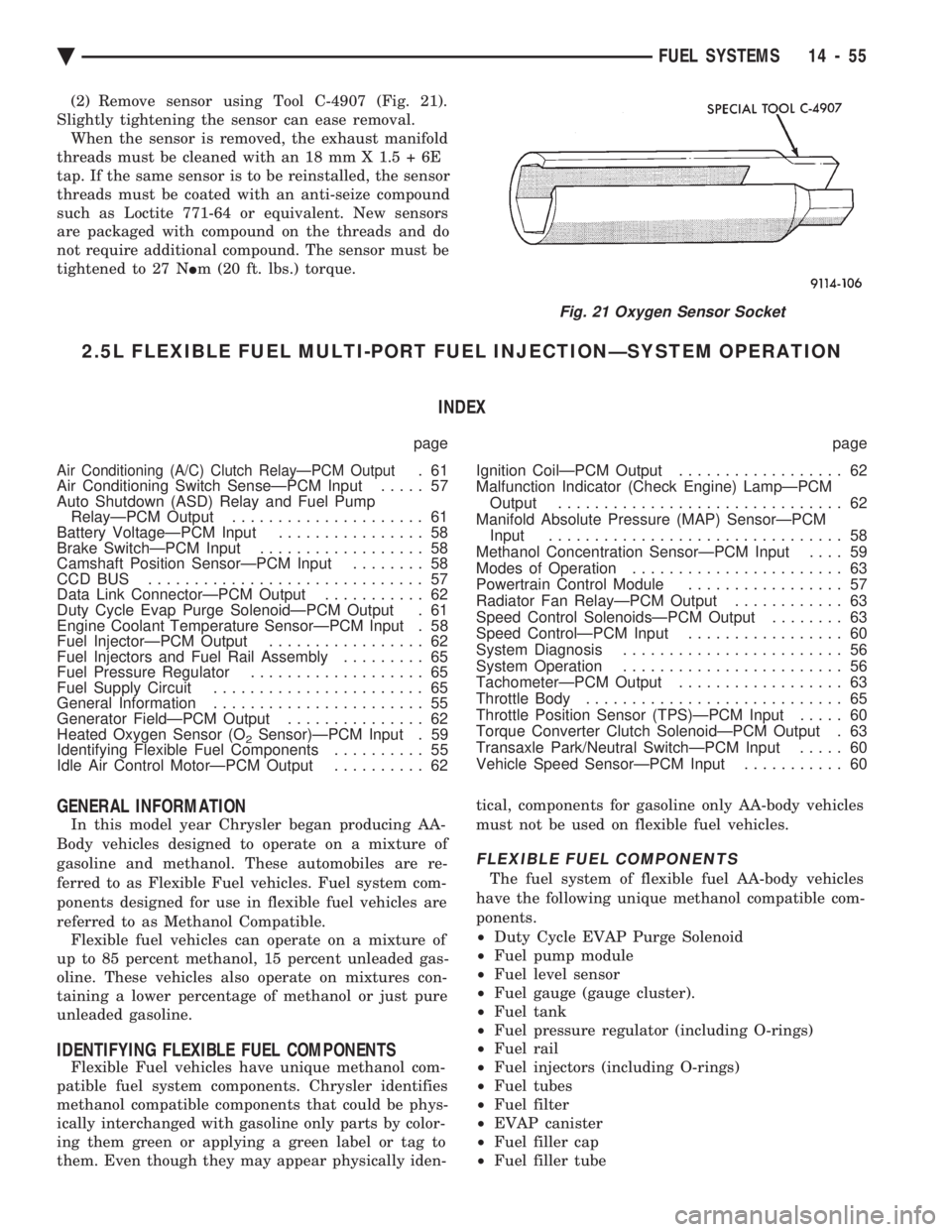
(2) Remove sensor using Tool C-4907 (Fig. 21).
Slightly tightening the sensor can ease removal. When the sensor is removed, the exhaust manifold
threads must be cleaned with an 18 mm X 1.5 + 6E
tap. If the same sensor is to be reinstalled, the sensor
threads must be coated with an anti-seize compound
such as Loctite 771-64 or equivalent. New sensors
are packaged with compound on the threads and do
not require additional compound. The sensor must be
tightened to 27 N Im (20 ft. lbs.) torque.
2.5L FLEXIBLE FUEL MULTI-PORT FUEL INJECTIONÐSYSTEM OPERATION
INDEX
page page
Air Conditioning (A/C) Clutch RelayÐPCM Output.61
Air Conditioning Switch SenseÐPCM Input ..... 57
Auto Shutdown (ASD) Relay and Fuel Pump RelayÐPCM Output ..................... 61
Battery VoltageÐPCM Input ................ 58
Brake SwitchÐPCM Input .................. 58
Camshaft Position SensorÐPCM Input ........ 58
CCD BUS .............................. 57
Data Link ConnectorÐPCM Output ........... 62
Duty Cycle Evap Purge SolenoidÐPCM Output . 61
Engine Coolant Temperature SensorÐPCM Input . 58
Fuel InjectorÐPCM Output ................. 62
Fuel Injectors and Fuel Rail Assembly ......... 65
Fuel Pressure Regulator ................... 65
Fuel Supply Circuit ....................... 65
General Information ....................... 55
Generator FieldÐPCM Output ............... 62
Heated Oxygen Sensor (O
2Sensor)ÐPCM Input . 59
Identifying Flexible Fuel Components .......... 55
Idle Air Control MotorÐPCM Output .......... 62 Ignition CoilÐPCM Output
.................. 62
Malfunction Indicator (Check Engine) LampÐPCM Output ............................... 62
Manifold Absolute Pressure (MAP) SensorÐPCM Input ................................ 58
Methanol Concentration SensorÐPCM Input .... 59
Modes of Operation ....................... 63
Powertrain Control Module ................. 57
Radiator Fan RelayÐPCM Output ............ 63
Speed Control SolenoidsÐPCM Output ........ 63
Speed ControlÐPCM Input ................. 60
System Diagnosis ........................ 56
System Operation ........................ 56
TachometerÐPCM Output .................. 63
Throttle Body ............................ 65
Throttle Position Sensor (TPS)ÐPCM Input ..... 60
Torque Converter Clutch SolenoidÐPCM Output . 63
Transaxle Park/Neutral SwitchÐPCM Input ..... 60
Vehicle Speed SensorÐPCM Input ........... 60
GENERAL INFORMATION
In this model year Chrysler began producing AA-
Body vehicles designed to operate on a mixture of
gasoline and methanol. These automobiles are re-
ferred to as Flexible Fuel vehicles. Fuel system com-
ponents designed for use in flexible fuel vehicles are
referred to as Methanol Compatible. Flexible fuel vehicles can operate on a mixture of
up to 85 percent methanol, 15 percent unleaded gas-
oline. These vehicles also operate on mixtures con-
taining a lower percentage of methanol or just pure
unleaded gasoline.
IDENTIFYING FLEXIBLE FUEL COMPONENTS
Flexible Fuel vehicles have unique methanol com-
patible fuel system components. Chrysler identifies
methanol compatible components that could be phys-
ically interchanged with gasoline only parts by color-
ing them green or applying a green label or tag to
them. Even though they may appear physically iden- tical, components for gasoline only AA-body vehicles
must not be used on flexible fuel vehicles.
FLEXIBLE FUEL COMPONENTS
The fuel system of flexible fuel AA-body vehicles
have the following unique methanol compatible com-
ponents.
² Duty Cycle EVAP Purge Solenoid
² Fuel pump module
² Fuel level sensor
² Fuel gauge (gauge cluster).
² Fuel tank
² Fuel pressure regulator (including O-rings)
² Fuel rail
² Fuel injectors (including O-rings)
² Fuel tubes
² Fuel filter
² EVAP canister
² Fuel filler cap
² Fuel filler tube
Fig. 21 Oxygen Sensor Socket
Ä FUEL SYSTEMS 14 - 55
Page 1817 of 2438
2.5L FLEXIBLE FUEL MULTI-PORT FUEL INJECTIONÐSERVICE PROCEDURES INDEX
page page
Fuel Injector ............................. 80
Fuel Injector Rail Assembly ................. 79
Fuel Pressure Regulator .................... 81
Fuel System Pressure Release Procedure ...... 78
General Information ....................... 77
Heated Oxygen Sensor (O
2Sensor) ........... 82
Identifying Flexible Fuel Components .......... 77
Idle Air Control Motor ...................... 78 Manifold Absolute Pressure (MAP) Sensor
Service ............................... 82
Methanol Concentration Sensor .............. 82
PCM Service ............................ 82
Service Precautions for Flexible Fuel Vehicles .... 77
Throttle Body ............................ 77
Throttle Body Removal ..................... 79
Throttle Position Sensor (TPS) ............... 78
GENERAL INFORMATION
In this model year Chrysler began producing AA-
Body vehicles designed to operate on a mixture of
gasoline and methanol. These automobiles are referred
to as Flexible Fuel vehicles. Fuel system components
designed for use in flexible fuel vehicles are referred to
as Methanol Compatible. Flexible fuel vehicles can operate on a mixture of up
to 85 percent methanol, 15 percent unleaded gasoline.
These vehicles also operate on mixtures containing a
lower percentage of methanol or just pure unleaded
gasoline.
SERVICE PRECAUTIONS FOR FLEXIBLE FUEL
VEHICLES
Methanol is more toxic than gasoline. Always release
fuel system pressure before servicing fuel system com-
ponents and wear methanol resistant gloves and eye
protection. Avoid breathing methanol vapors or ingesting
methanol. Headaches, dizziness and even unconscious-
ness could result from breathing these vapors. Serious
injury, blindness and even death could result from
ingesting methanol. Methanol vapors are extremely flammable and can
travel along the ground. Service vehicles in well ven-
tilated areas and avoid ignition sources. Never smoke
while servicing the vehicle. Do not allow methanol to contact skin. Prolonged
contact with methanol can cause dry skin or an allergic
skin reaction. Also, prolonged contact could result in
absorption through the skin.
IDENTIFYING FLEXIBLE FUEL COMPONENTS
Flexible Fuel vehicles have unique methanol compat-
ible fuel system components. Chrysler identifies methanol
compatible components that could be physically inter-
changed with gasoline only parts by coloring them green
or applying a green label or tag to them. Even though
they may appear physically identical, components
for gasoline only AA-body vehicles must not be used
on flexible fuel vehicles.
FLEXIBLE FUEL COMPONENTS
The fuel system of flexible fuel AA-body vehicles have
the following unique methanol compatible components.
² Duty cycle EVAP purge solenoid
² EVAP canister
² Fuel pump module
² Fuel level sensor
² Fuel gauge (gauge cluster).
² Fuel tank
² Fuel pressure regulator (including O-rings)
² Fuel rail
² Fuel injectors (including O-rings)
² Fuel tubes
² Fuel filter
² Fuel filler cap
² Fuel filler tube
² Methanol concentration sensor
² Pressure relief/rollover valve
² PCV Valve
² All fuel system and emission system hoses and tubes
THROTTLE BODY
WARNING: THROTTLE BODIES DESIGNED FOR
GASOLINE ONLY VEHICLES CANNOT BE USED ON
FLEXIBLE FUEL AA-BODY VEHICLES. WHEN RE-
PLACING THE THROTTLE BODY OF A FLEXIBLE
FUEL VEHICLE, ONLY USE AN ORIGINAL EQUIP-
MENT REPLACEMENT.
When servicing throttle body components, always
reassemble components with new O-rings and seals
where applicable. Never use lubricants on O-rings or
seals, damage may result. If assembly of component is
difficult, use water to aid assembly. Use care when
removing hoses to prevent damage to hose or hose
nipple.
Ä FUEL SYSTEMS 14 - 77
Page 1878 of 2438
3.0L MULTI-PORT FUEL INJECTIONÐSERVICE PROCEDURES INDEX
page page
Idle Air Control Motor .................... 138
Canister Purge Solenoid Service ............ 143
Fuel Injector Rail Assembly ................ 139
Fuel Injectors .......................... 142
Fuel Pressure Regulator Service ............ 141
Fuel System Pressure Release Procedure ..... 138 Heated Oxygen Sensor (O
2Sensor)
......... 144
Manifold Absolute Pressure (MAP) Sensor ..... 143
PCM ................................. 143
Throttle Body ........................... 138
Throttle Body Service .................... 138
Throttle Position Sensor .................. 138
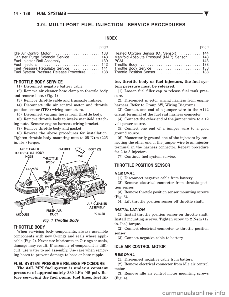
THROTTLE BODY SERVICE
(1) Disconnect negative battery cable.
(2) Remove air cleaner hose clamp to throttle body
and remove hose. (Fig. 1) (3) Remove throttle cable and transaxle linkage.
(4) Disconnect idle air control motor and throttle
position sensor (TPS) wiring connectors. (5) Disconnect vacuum hoses from throttle body.
(6) Remove throttle body to intake manifold attach-
ing nuts. Remove engine harness wiring bracket. (7) Remove throttle body and gasket.
(8) Reverse the above procedures for installation.
Tighten throttle body mounting nuts to 25 N Im (225
in. lbs.) torque.
THROTTLE BODY
When servicing body components, always assemble
components with new O-rings and seals where appli-
cable (Fig. 2). Never use lubricants on O-rings or seals,
damage may result. If assembly of component is diffi-
cult, use water to aid assembly. Use care when remov-
ing hoses to prevent damage to hose or hose nipple.
FUEL SYSTEM PRESSURE RELEASE PROCEDURE
The 3.0L MPI fuel system is under a constant
pressure of approximately 330 kPa (48 psi). Be-
fore servicing the fuel pump, fuel lines, fuel fil- ter, throttle body or fuel injectors, the fuel sys-
tem pressure must be released. (1) Loosen fuel filler cap to release fuel tank pres-
sure. (2) Disconnect injector wiring harness from engine
harness. Refer to Group 8W, Wiring Diagrams. (3) Connect one end of a jumper wire to the A142
circuit terminal of the fuel rail harness connector. (4) Connect the other end of the jumper wire to a 12
volt power source. (5) Connect one end of a jumper wire to a good
ground source. (6) Momentarily ground one of the injectors by con-
necting the other end of the jumper wire to an injector
terminal in the harness connector. Repeat procedure
for 2 to 3 injectors. (7) Continue fuel system service.
THROTTLE POSITION SENSOR
REMOVAL
(1) Disconnect negative cable from battery.
(2) Remove electrical connector from throttle posi-
tion sensor. (3) Remove throttle position sensor mounting screws
(Fig. 3). (4) Lift throttle position sensor off throttle shaft.
INSTALLATION
(1) Install throttle position sensor on throttle shaft.
Install mounting screws. Tighten screw to 2 N Im (17
in. lbs.) torque. (2) Connect electrical connector to throttle position
sensor. (3) Connect negative cable to battery.
IDLE AIR CONTROL MOTOR
REMOVAL
(1) Disconnect negative cable from battery.
(2) Remove electrical connector from idle air control
motor. (3) Remove idle air control motor mounting screws
(Fig. 4).
Fig. 1 Throttle Body
14 - 138 FUEL SYSTEMS Ä