fuel tank removal CHEVROLET DYNASTY 1993 Service Manual
[x] Cancel search | Manufacturer: CHEVROLET, Model Year: 1993, Model line: DYNASTY, Model: CHEVROLET DYNASTY 1993Pages: 2438, PDF Size: 74.98 MB
Page 33 of 2438
COMPONENT AND SYSTEM INDEX
Name Group-page Name Group-page
AUDIO SYSTEM ............................ 8F-1
ANTENNAS ............................ 8F-20
COMPACT DISC PLAYER ................... 8F-30
RADIOS ............................... 8F-1
SPEAKERS ............................. 8F-24
BATTERY/STARTER/GENERATOR SERVICE ..........8B-1
BATTERY REMOVAL, INSTALLATION AND SERVICE . . 8B-1
GENERATOR ............................ 8B-9
SPECIFICATIONS ........................ 8B-12
STARTER .............................. 8B-4
BATTERY/STARTING/CHARGING SYSTEMS DIAGNOSTICS ........................... 8A-1
BATTERY TEST PROCEDURES ON-VEHICLE .......8A-3
FAULT CODESÐON BOARD DIAGNOSTICS .......8A-23
GENERAL INFORMATION .................... 8A-1
GENERATOR TEST PROCEDURES ON VEHICLE ....8A-19
IGNITION OFF DRAW (IOD) ..................8A-9
SPECIFICATIONS ........................ 8A-28
STARTER TEST PROCEDURES ON VEHICLE ......8A-11
CHIME WARNING/REMINDER SYSTEM ............8U-1
EMISSION CONTROL SYSTEMS .................25-1
EVAPORATIVE EMISSION CONTROLS ...........25-1
EXHAUST EMISSION CONTROLS ..............25-17
FUEL SYSTEMS ............................ 14-1
2.2L TURBO III MULTI-PORT FUEL INJECTIONÐ GENERAL DIAGNOSIS ................... 14-95
2.2L TURBO III MULTI-PORT FUEL INJECTIONÐ ON-BOARD DIAGNOSTICS ................14-100
2.2L TURBO III MULTI-PORT FUEL INJECTIONÐ SERVICE PROCEDURES .................14-107
2.2L TURBO III MULTI-PORT FUEL INJECTIONÐ SYSTEM OPERATION .................... 14-83
2.2L/2.5L SINGLE POINT FUEL INJECTIONÐ GENERAL DIAGNOSIS ................... 14-35
2.2L/2.5L SINGLE POINT FUEL INJECTIONÐ ON-BOARD DIAGNOSTICS .................14-41
2.2L/2.5L SINGLE POINT FUEL INJECTIONÐ SERVICE PROCEDURES .................. 14-48
2.2L/2.5L SINGLE POINT FUEL INJECTIONÐ SYSTEM OPERATION .................... 14-24
2.5L FLEXIBLE FUEL MULTI-PORT FUEL INJECTIONÐGENERAL DIAGNOSIS ..........14-66
2.5L FLEXIBLE FUEL MULTI-PORT FUEL INJECTIONÐON-BOARD DIAGNOSTICS ........14-70
2.5L FLEXIBLE FUEL MULTI-PORT FUEL INJECTIONÐSERVICE PROCEDURES .........14-77
2.5L FLEXIBLE FUEL MULTI-PORT FUEL INJECTIONÐSYSTEM OPERATION ...........14-55
3.0L MULTI-PORT FUEL INJECTIONÐGENERAL DIAGNOSIS .......................... 14-125
3.0L MULTI-PORT FUEL INJECTIONÐON-BOARD DIAGNOSTICS ........................ 14-130
3.0L MULTI-PORT FUEL INJECTIONÐSERVICE PROCEDURES ........................ 14-138
3.0L MULTI-PORT FUEL INJECTIONÐSYSTEM OPERATION ......................... 14-113
3.3L AND 3.8L MULTI-PORT FUEL INJECTIONÐ GENERAL DIAGNOSIS ................... 14-157 3.3L AND 3.8L MULTI-PORT FUEL INJECTIONÐ
ON-BOARD DIAGNOSTICS ................14-162
3.3L AND 3.8L MULTI-PORT FUEL INJECTIONÐ SERVICE PROCEDURES .................14-169
3.3L AND 3.8L MULTI-PORT FUEL INJECTIONÐ SYSTEM OPERATION ................... 14-145
ACCELERATOR PEDAL AND THROTTLE CABLE ....14-21
FUEL DELIVERY SYSTEM .................... 14-3
FUEL TANKS ........................... 14-14
GENERAL INFORMATION .................... 14-1
SPECIFICATIONS ........................ 14-178
HORNS ................................. 8G-1
IGNITION SYSTEMS ......................... 8D-1
2.2L TBI, 2.5L TBI, 2.5L MPI AND 3.0L IGNITION SYSTEMSÐDIAGNOSTIC PROCEDURES .......8D-11
2.2L TBI, 2.5L TBI, 2.5L MPI AND 3.0L IGNITION SYSTEMSÐSERVICE PROCEDURES ..........8D-14
2.2L TBI, 2.5L TBI, 2.5L MPI AND 3.0L IGNITION SYSTEMSÐSYSTEM OPERATION ............8D-1
2.2L TURBO III, 3.3L AND 3.8L IGNITION SYSTEMÐDIAGNOSTIC PROCEDURES ........8D-35
2.2L TURBO III, 3.3L AND 3.8L IGNITION SYSTEMÐSYSTEM OPERATION ............8D-24
2.2L TURBO III, 3.3L AND 3.8L IGNITION SYSTEMSÐSERVICE PROCEDURES ..........8D-39
IGNITION SWITCH ....................... 8D-45
SPECIFICATIONS ........................ 8D-47
INSTRUMENT PANEL AND GAUGES ...............8E-1
AA BODY .............................. 8E-1
AC AND AY BODIES ...................... 8E-23
AG AND AJ BODIES ...................... 8E-42
AP BODY ............................. 8E-58
LAMPS .................................. 8L-1
BULB APPLICATION TABLE ..................8L-38
CONCEALED HEADLAMPS ..................8L-27
EXTERIOR LAMP SWITCHES AND HEADLAMP ALIGNMENT ........................... 8L-3
EXTERIOR LAMP SYSTEMS .................8L-25
EXTERIOR LAMPSÐAA BODY ................8L-7
EXTERIOR LAMPSÐAC BODY ...............8L-10
EXTERIOR LAMPSÐAG BODY ...............8L-14
EXTERIOR LAMPSÐAJ BODY ................8L-16
EXTERIOR LAMPSÐAP BODY ...............8L-19
EXTERIOR LAMPSÐAY-BODY ................8L-22
GENERAL INFORMATION .................... 8L-1
ILLUMINATED ENTRY SYSTEM ...............8L-33
OVERHEAD CONSOLE ........................ 8C-1
AA BODY .............................. 8C-1
AC AND AY BODY ........................ 8C-6
AG AND AJ BODIES ...................... 8C-13
AP BODY ............................. 8C-21
POWER LOCKS ............................ 8P-1
POWER MIRRORS ..........................8T-1
POWER SEATS ............................ 8R-1
POWER WINDOWS .......................... 8S-1
REAR WINDOW DEFOGGER .................... 8N-1
RESTRAINT SYSTEMS ....................... 8M-1
TURN SIGNALS AND HAZARD WARNING FLASHER ....8J-1
VEHICLE SPEED CONTROL .................... 8H-1
Page 522 of 2438
(b) Refer to sending unit removal Group 14, Fuel.
(c) Connect sending unit wire and jumper wire
as described in the test procedure.
(5) If fuel gauge now checks within specifications,
original sending unit is electrically okay, check fol-
lowing as a possible cause: (a) Ground wire from sending unit to left side
cowl for continuity. (b) Sending unit deformed. Make sure sending
unit float arm moves freely and pick up tube is not
bent upwards creating an interference with bottom
of tank and inspect float. (c) Sending unit improperly installed. Install
properly. (d) Mounting flange on fuel tank for sending
unit deformed. Feel for interference fit of sending
unit to bottom of tank. It is permissible to bend
pick up tube down a little near mounting flange to
gain interference fit. (e) Fuel tank bottom deformed, causing improper
positioning of sending unit pick up tube. Replace or
repair tank and recheck sending unit.
GAUGE CALIBRATION
(1) Remove the gauge.
(2) Check for ignition voltage and ground to the
gauge. (3) With the ignition key in the OFF position, re-
place gauge. Turn the ignition key to the ON posi-
tion. To test oil pressure gauge engine must be
running. When testing oil or temperature gauge the
engine should be at normal operating temperature.
Record the gauge position. (4) Remove gauge and record the resistance be-
tween the sending unit pin and the gauge ground
pin. When checking gauges, it is important to have
the same engine temperature and speed when noting
gauge position. The time between gauge reading and
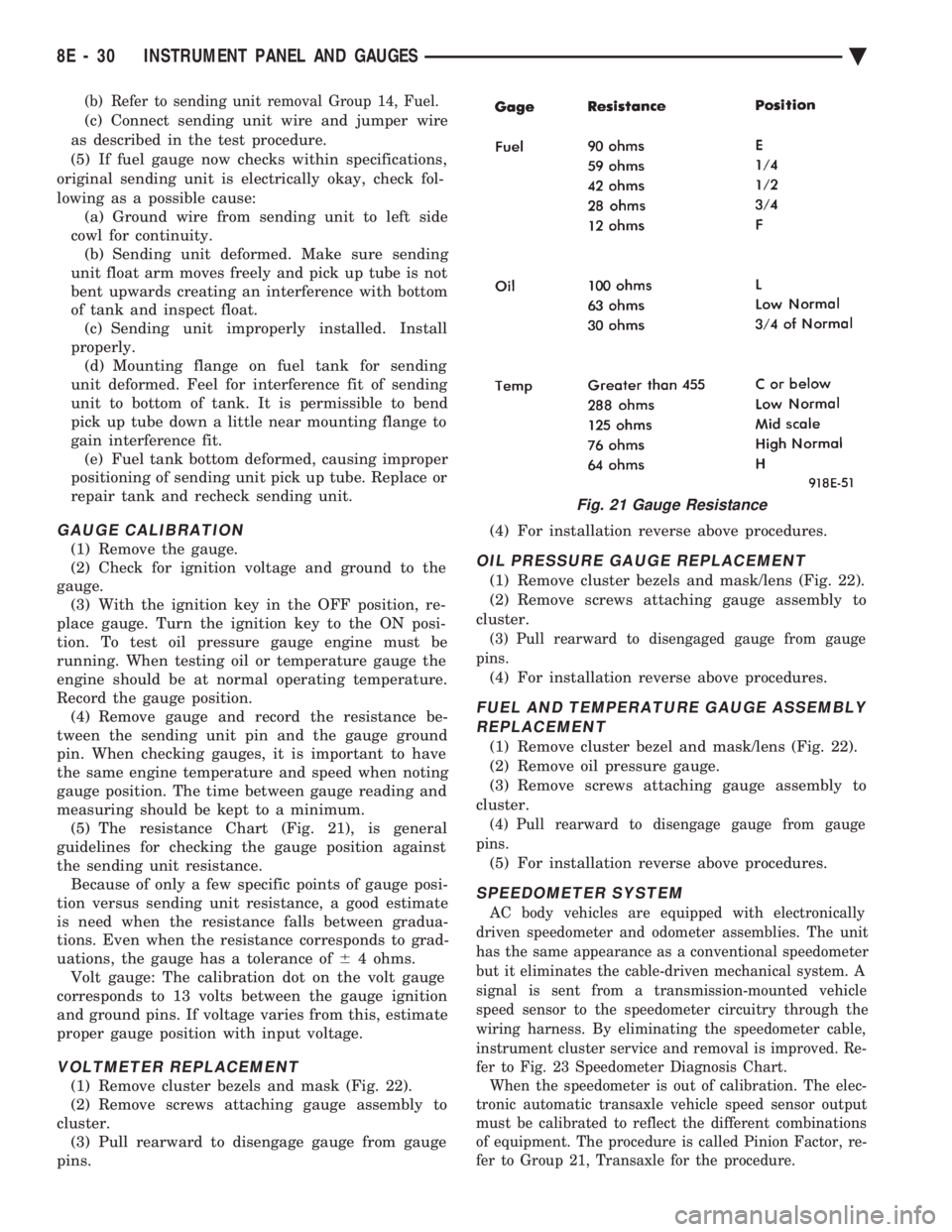
measuring should be kept to a minimum. (5) The resistance Chart (Fig. 21), is general
guidelines for checking the gauge position against
the sending unit resistance. Because of only a few specific points of gauge posi-
tion versus sending unit resistance, a good estimate
is need when the resistance falls between gradua-
tions. Even when the resistance corresponds to grad-
uations, the gauge has a tolerance of 64 ohms.
Volt gauge: The calibration dot on the volt gauge
corresponds to 13 volts between the gauge ignition
and ground pins. If voltage varies from this, estimate
proper gauge position with input voltage.
VOLTMETER REPLACEMENT
(1) Remove cluster bezels and mask (Fig. 22).
(2) Remove screws attaching gauge assembly to
cluster. (3) Pull rearward to disengage gauge from gauge
pins. (4) For installation reverse above procedures.
OIL PRESSURE GAUGE REPLACEMENT
(1) Remove cluster bezels and mask/lens (Fig. 22).
(2) Remove screws attaching gauge assembly to
cluster.
(3) Pull rearward to disengaged gauge from gauge
pins.
(4) For installation reverse above procedures.
FUEL AND TEMPERATURE GAUGE ASSEMBLY REPLACEMENT
(1) Remove cluster bezel and mask/lens (Fig. 22).
(2) Remove oil pressure gauge.
(3) Remove screws attaching gauge assembly to
cluster.
(4) Pull rearward to disengage gauge from gauge
pins.
(5) For installation reverse above procedures.
SPEEDOMETER SYSTEM
AC body vehicles are equipped with electronically
driven speedometer and odometer assemblies. The unit
has the same appearance as a conventional speedometer
but it eliminates the cable-driven mechanical system. A
signal is sent from a transmission-mounted vehicle
speed sensor to the speedometer circuitry through the
wiring harness. By eliminating the speedometer cable,
instrument cluster service and removal is improved. Re-
fer to Fig. 23 Speedometer Diagnosis Chart. When the speedometer is out of calibration. The elec-
tronic automatic transaxle vehicle speed sensor output
must be calibrated to reflect the different combinations
of equipment. The procedure is called Pinion Factor, re-
fer to Group 21, Transaxle for the procedure.
Fig. 21 Gauge Resistance
8E - 30 INSTRUMENT PANEL AND GAUGES Ä
Page 555 of 2438
(f) If everything checks out OK, refer to Sending
Unit Test.
(4) With the ignition switch in the ON position,
check for battery voltage across the ignition pin and
the ground pin. (5) If fuel gauge meets specifications check fuel
tank and original fuel tank sending unit as follows: (a) Carefully remove fuel tank sending unit from
tank. (b) Refer to sending unit removal Group 14,
Fuel. (c) Connect sending unit wire and jumper wire
as described in the test procedure.
(6) If fuel gauge now checks within specifications,
original sending unit is electrically okay, check fol-
lowing as a possible cause: (a) Ground wire from sending unit to left side
cowl for continuity. (b) Sending unit deformed. Make sure sending
unit float arm moves freely and pick up tube is not
bent upwards creating an interference with bottom
of tank and inspect float. (c) Sending unit improperly installed. Install
properly. (d) Mounting flange on fuel tank for sending
unit deformed. Feel for interference fit of sending
unit to bottom of tank. It is permissible to bend
pick up tube down a little near mounting flange to
gain interference fit. (e) Fuel tank bottom deformed, causing improper
positioning of sending unit pick up tube. Replace or
repair tank and recheck sending unit.GAUGE CALIBRATION
(1) Remove the gauge.
(2) Check for ignition voltage and ground to the
gauge. (3) With the ignition key in the OFF position, re-
place gauge. Turn the ignition key to the ON posi-
tion. To test oil pressure gauge engine must be
running. When testing oil or temperature gauge the
engine should be at normal operating temperature.
Record the gauge position. (4) Remove gauge and record the resistance be-
tween the sending unit pin and the gauge ground
pin. When checking gauges, it is important to have
the same engine temperature and speed when noting
gauge position. The time between gauge reading and
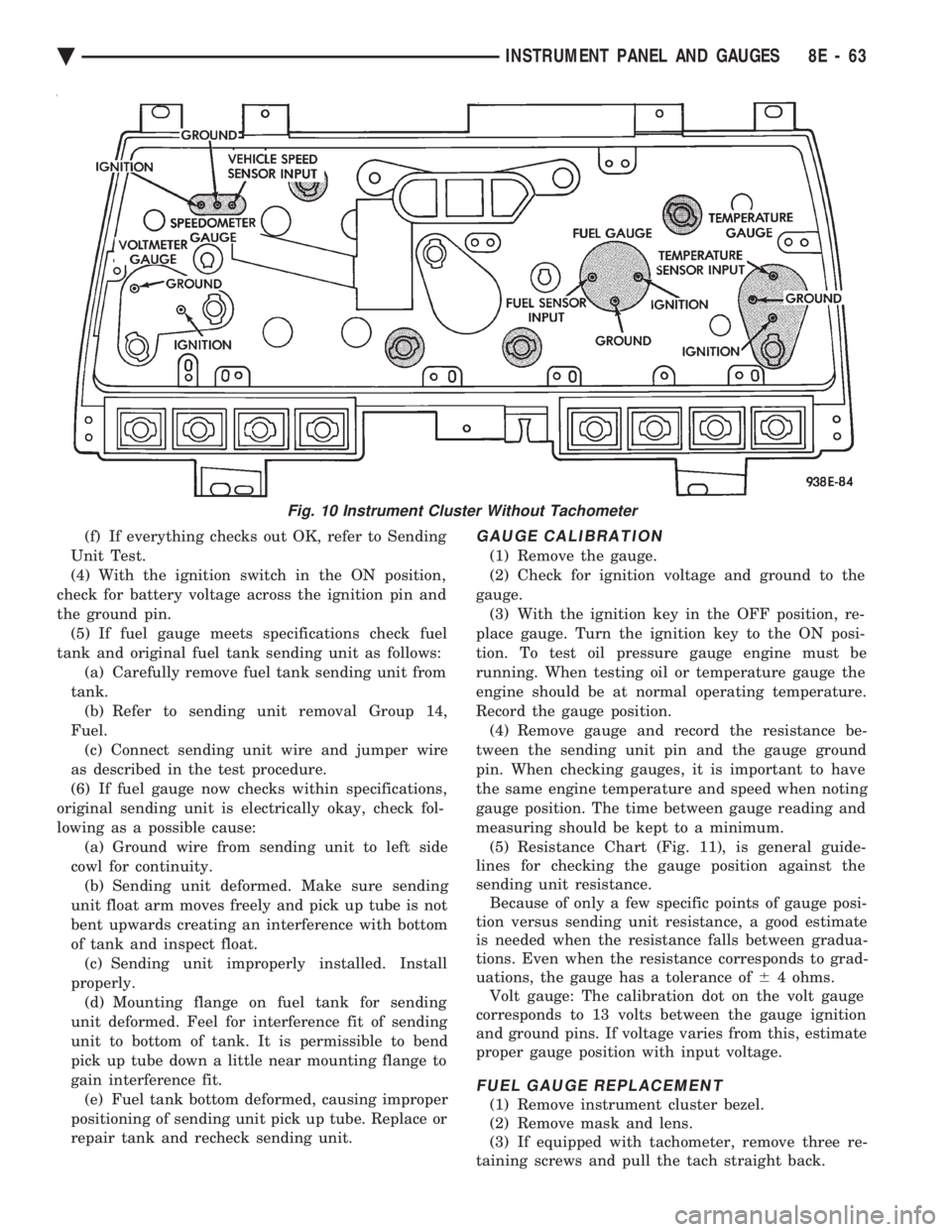
measuring should be kept to a minimum. (5) Resistance Chart (Fig. 11), is general guide-
lines for checking the gauge position against the
sending unit resistance. Because of only a few specific points of gauge posi-
tion versus sending unit resistance, a good estimate
is needed when the resistance falls between gradua-
tions. Even when the resistance corresponds to grad-
uations, the gauge has a tolerance of 64 ohms.
Volt gauge: The calibration dot on the volt gauge
corresponds to 13 volts between the gauge ignition
and ground pins. If voltage varies from this, estimate
proper gauge position with input voltage.
FUEL GAUGE REPLACEMENT
(1) Remove instrument cluster bezel.
(2) Remove mask and lens.
(3) If equipped with tachometer, remove three re-
taining screws and pull the tach straight back.
Fig. 10 Instrument Cluster Without Tachometer
Ä INSTRUMENT PANEL AND GAUGES 8E - 63
Page 1702 of 2438
for diagnostic and service procedures on the air control
valve and temperature sensor located in the air
cleaner.
INTAKE AND EXHAUST MANIFOLDS SERVICEÐTBI
ENGINE
Intake and exhaust manifolds use a one piece gasket.
Service procedures requiring removal and installation
( of either ) must include both manifolds.
FUEL SYSTEM PRESSURE RELEASE PROCE- DURE
The Fuel System is under a constant pressure
of at least 265 kPa (39 psi). Before servicing the
fuel pump, fuel lines, fuel filter, throttle body or
fuel injector, the fuel system pressure must be
released. (a) Loosen fuel filler cap to release fuel tank pres-
sure. (b) Disconnect injector wiring harness from engine
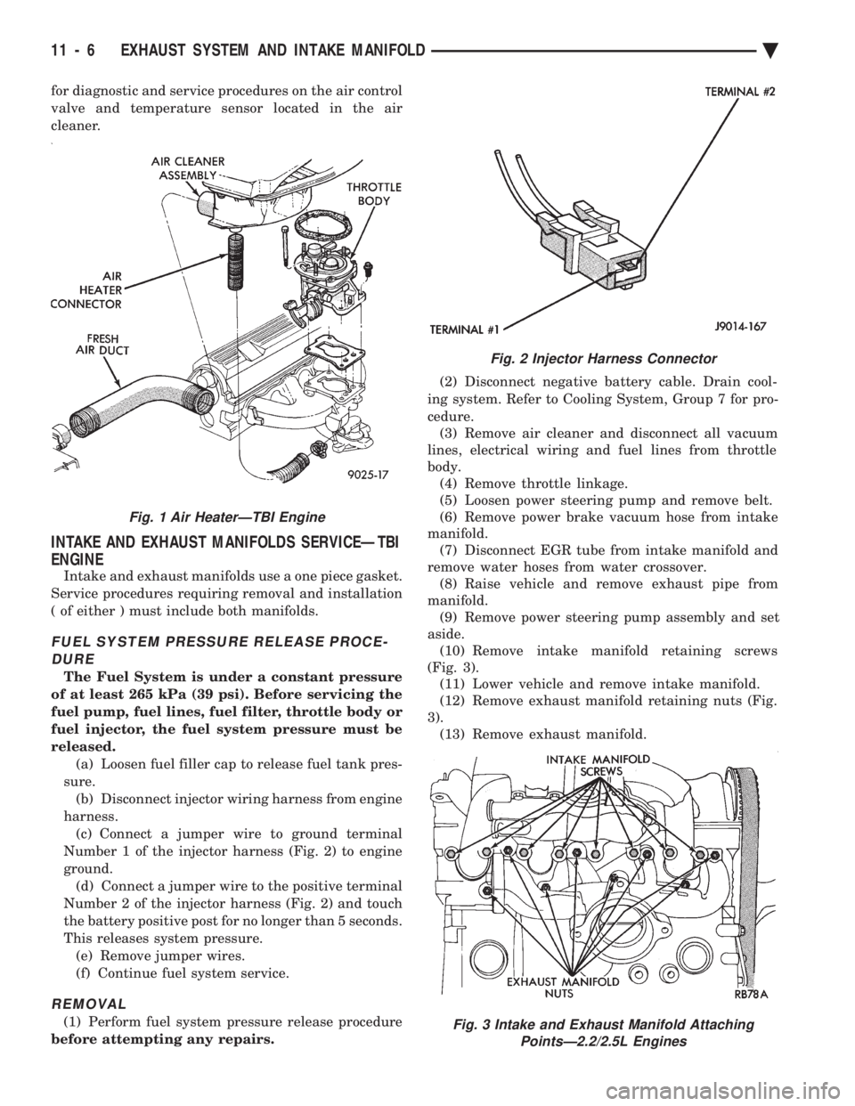
harness. (c) Connect a jumper wire to ground terminal
Number 1 of the injector harness (Fig. 2) to engine
ground. (d) Connect a jumper wire to the positive terminal
Number 2 of the injector harness (Fig. 2) and touch
the battery positive post for no longer than 5 seconds.
This releases system pressure. (e) Remove jumper wires.
(f) Continue fuel system service.
REMOVAL
(1) Perform fuel system pressure release procedure
before attempting any repairs. (2) Disconnect negative battery cable. Drain cool-
ing system. Refer to Cooling System, Group 7 for pro-
cedure. (3) Remove air cleaner and disconnect all vacuum
lines, electrical wiring and fuel lines from throttle
body. (4) Remove throttle linkage.
(5) Loosen power steering pump and remove belt.
(6) Remove power brake vacuum hose from intake
manifold. (7) Disconnect EGR tube from intake manifold and
remove water hoses from water crossover. (8) Raise vehicle and remove exhaust pipe from
manifold. (9) Remove power steering pump assembly and set
aside. (10) Remove intake manifold retaining screws
(Fig. 3). (11) Lower vehicle and remove intake manifold.
(12) Remove exhaust manifold retaining nuts (Fig.
3). (13) Remove exhaust manifold.
Fig. 2 Injector Harness Connector
Fig. 3 Intake and Exhaust Manifold Attaching PointsÐ2.2/2.5L Engines
Fig. 1 Air HeaterÐTBI Engine
11 - 6 EXHAUST SYSTEM AND INTAKE MANIFOLD Ä
Page 1710 of 2438
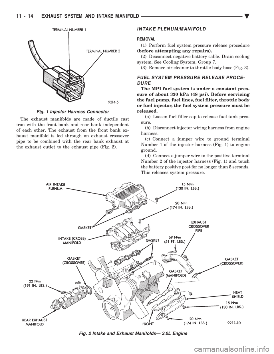
The exhaust manifolds are made of ductile cast
iron with the front bank and rear bank independent
of each other. The exhaust from the front bank ex-
haust manifold is led through on exhaust crossover
pipe to be combined with the rear bank exhaust at
the exhaust outlet to the exhaust pipe (Fig. 2).
INTAKE PLENUM/MANIFOLD
REMOVAL
(1) Perform fuel system pressure release procedure
(before attempting any repairs). (2) Disconnect negative battery cable. Drain cooling
system. See Cooling System, Group 7. (3) Remove air cleaner to throttle body hose (Fig. 3).
FUEL SYSTEM PRESSURE RELEASE PROCE-DURE
The MPI fuel system is under a constant pres-
sure of about 330 kPa (48 psi). Before servicing
the fuel pump, fuel lines, fuel filter, throttle body
or fuel injector, the fuel system pressure must be
released .
(a) Loosen fuel filler cap to release fuel tank pres-
sure. (b) Disconnect injector wiring harness from engine
harness. (c) Connect a jumper wire to ground terminal
Number 1 of the injector harness (Fig. 1) to engine
ground. (d) Connect a jumper wire to the positive terminal
Number 2 of the injector harness (Fig. 1) and touch
the battery positive post for no longer than 5 seconds.
This releases system pressure.
Fig. 1 Injector Harness Connector
Fig. 2 Intake and Exhaust ManifoldsÐ 3.0L Engine
11 - 14 EXHAUST SYSTEM AND INTAKE MANIFOLD Ä
Page 1715 of 2438
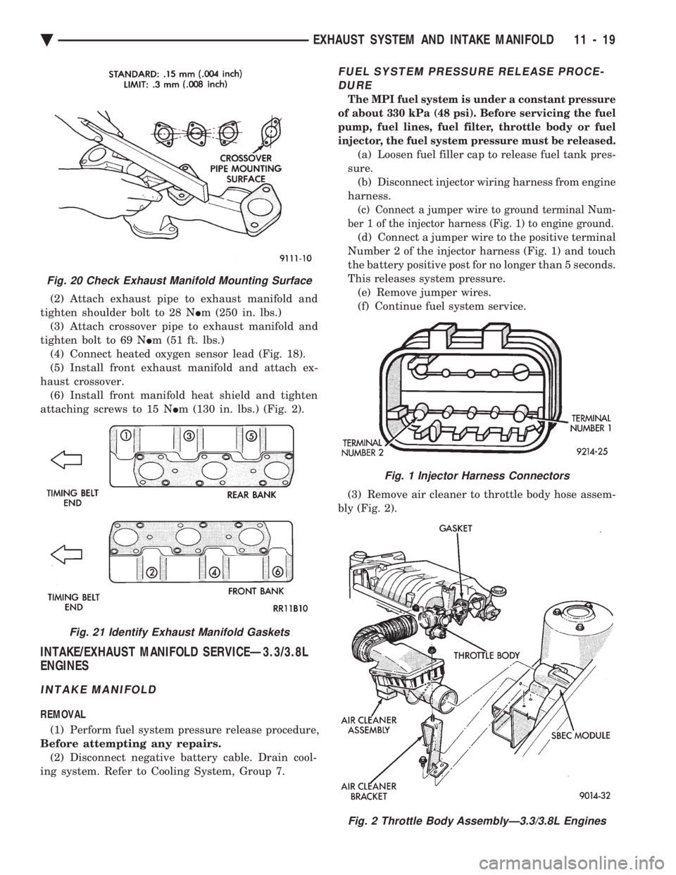
(2) Attach exhaust pipe to exhaust manifold and
tighten shoulder bolt to 28 N Im (250 in. lbs.)
(3) Attach crossover pipe to exhaust manifold and
tighten bolt to 69 N Im (51 ft. lbs.)
(4) Connect heated oxygen sensor lead (Fig. 18).
(5) Install front exhaust manifold and attach ex-
haust crossover. (6) Install front manifold heat shield and tighten
attaching screws to 15 N Im (130 in. lbs.) (Fig. 2).
INTAKE/EXHAUST MANIFOLD SERVICEÐ3.3/3.8L
ENGINES
INTAKE MANIFOLD
REMOVAL
(1) Perform fuel system pressure release procedure,
Before attempting any repairs. (2) Disconnect negative battery cable. Drain cool-
ing system. Refer to Cooling System, Group 7.
FUEL SYSTEM PRESSURE RELEASE PROCE- DURE
The MPI fuel system is under a constant pressure
of about 330 kPa (48 psi). Before servicing the fuel
pump, fuel lines, fuel filter, throttle body or fuel
injector, the fuel system pressure must be released.
(a) Loosen fuel filler cap to release fuel tank pres-
sure. (b) Disconnect injector wiring harness from engine
harness.
(c) Connect a jumper wire to ground terminal Num-
ber 1 of the injector harness (Fig. 1) to engine ground.
(d) Connect a jumper wire to the positive terminal
Number 2 of the injector harness (Fig. 1) and touch
the battery positive post for no longer than 5 seconds.
This releases system pressure. (e) Remove jumper wires.
(f) Continue fuel system service.
(3) Remove air cleaner to throttle body hose assem-
bly (Fig. 2).
Fig. 20 Check Exhaust Manifold Mounting Surface
Fig. 21 Identify Exhaust Manifold Gaskets
Fig. 1 Injector Harness Connectors
Fig. 2 Throttle Body AssemblyÐ3.3/3.8L Engines
Ä EXHAUST SYSTEM AND INTAKE MANIFOLD 11 - 19
Page 1743 of 2438
FUEL DELIVERY SYSTEM INDEX
page page
Chassis Fuel Tubes ...................... 11
Flexible Fuel Components ................... 3
Fuel FilterÐAll Vehicles .................... 9
Fuel Hoses, Clamps, and Quick Connect Fittings . 10
Fuel Pump Assembly ...................... 5
Fuel Pump Module Installation ............... 9
Fuel Pump Module Removal ................. 8
Fuel Pump Pressure TestÐ2.2L/2.5L TBI and 3.0L MPI Engines ........................... 7
Fuel Pump Pressure TestÐAll Except 2.2L/2.5L TBI and 3.0L MPI ....................... 6
Fuel Pump Strainer Service .................. 9 Fuel System Pressure
...................... 6
Fuel System Pressure Release ProcedureÐ 2.2L/2.5L TBI ........................... 4
Fuel System Pressure Release ProcedureÐ3.0L . . 5
Fuel System Pressure Release ProcedureÐExcept 2.2L/2.5L TBI and 3.0L ................... 4
General Information ........................ 3
Identifying Flexible Fuel Components .......... 3
Mechanical Malfunctions .................... 8
Methanol Concentration SensorÐFlexible Fuel AA-Body .............................. 4
Service Precautions for Flexible Fuel Vehicles .... 3
GENERAL INFORMATION
Beginning this model year, Chrysler began produc-
ing AA-Body vehicles designed to operate on a mix-
ture of gasoline and methanol. These automobiles are
referred to as Flexible Fuel vehicles. Flexible fuel vehicles can operate on a mixture of
up to 85 percent methanol, 15 percent unleaded gas-
oline. These vehicles also operate on mixtures con-
taining a lower percentage of methanol or just pure
unleaded gasoline. In many cases, the procedures for servicing flexible
fuel components is identical to gasoline only compo-
nents. Refer to the particular Service Procedure in
this section. If the service procedure for flexible fuel
component differs from a gasoline only component,
the title of each service procedure identifies the ap-
plication.
SERVICE PRECAUTIONS FOR FLEXIBLE FUEL
VEHICLES
Methanol is more toxic than gasoline. Always re-
lease fuel system pressure before servicing fuel sys-
tem components and wear methanol resistant gloves
and eye protection. Avoid breathing methanol vapors or ingesting
methanol. Headaches, dizziness and even uncon-
sciousness could result from breathing these vapors.
Serious injury, blindness and even death could result
from ingesting methanol. Methanol vapors are extremely flammable and can
travel along the ground. Service vehicles in well ven-
tilated areas and avoid ignition sources. Never
smoke while servicing the vehicle. Do not allow methanol to contact skin. Prolonged
contact with methanol can cause dry skin or an al-
lergic skin reaction. Also, prolonged contact could re-
sult in absorption through the skin.
IDENTIFYING FLEXIBLE FUEL COMPONENTS
Flexible Fuel vehicles have unique methanol com-
patible fuel system components. Chrysler identifies
methanol compatible components that could be phys-
ically interchanged with gasoline only parts by color-
ing them green or applying a green label or tag to
them. Even though they may appear physically iden-
tical, components for gasoline only vehicles must not
be used on flexible fuel vehicles.
FLEXIBLE FUEL COMPONENTS
Flexible fuel AA-body vehicles uses many unique
fuel system components. The unique parts are green
in appearance or have a green tag or label attached
to them. While components used on gasoline only ve-
hicles may look similar or identical, they cannot be
used on flexible fuel vehicles. When servicing a com-
ponent, always use an original equipment or equiva-
lent flexible fuel replacement. The fuel system of flexible fuel AA-body vehicles
have the following unique components.
² Fuel pump module
² Fuel level sensor
² Fuel gauge (gauge cluster).
² Fuel tank
² Fuel pressure regulator (including O-rings)
² Fuel rail
² Fuel injectors (including O-rings)
² Fuel tubes
² Fuel filter
² EVAP canister
² Fuel filler cap
² Fuel filler tube
² Pressure relief/Rollover valve
² All fuel system and emission system hoses and
tubes
Ä FUEL SYSTEMS 14 - 3
Page 1744 of 2438
INSTRUMENT PANEL CLUSTER IDENTIFICATIONÐFLEXIBLE FUEL AA-BODY
Flexible fuel A-Body vehicles use a unique gauge
cluster. To identify the cluster, remove it from the
instrument panel and check the number on the tag
on the top. If the part number matches the number
in the parts book for flexible fuel A-bodies, the vehi-
cle was built with the correct cluster. Refer to Group
8E, Instrument Panel and Gauges, for cluster re-
moval and installation.
METHANOL CONCENTRATION SENSORÐFLEXIBLE
FUEL AA-BODY
The methanol concentration sensor contains a mi-
croprocessor that determines the percentage of gaso-
line and methanol in the fuel system. From the
methanol concentration sensor input, the powertrain
control module (PCM) determines the amount of
methanol in the fuel. The vehicle can operate on a
mixtures up to 85 percent methanol, 15 percent gas-
oline. The methanol concentration sensor output voltages
varies with the percent of methanol in the fuel sys-
tem. The sensor output voltage (input for PCM)
ranges from 0.5 volts for pure gasoline to 4.75 volts
for 85 percent methanol. For two seconds at key ON
when the operator starts the vehicle, the sensor cal-
ibrates the PCM. During the calibration period the
sensor sends 4.45 volts to the PCM as a correction
factor. The methanol concentration sensor has a built-in
shutdown capability. If the sensor shuts down, it de-
faults to the previous learned value (output voltage
based on methanol percentage of fuel). The methanol concentration sensor attaches to a
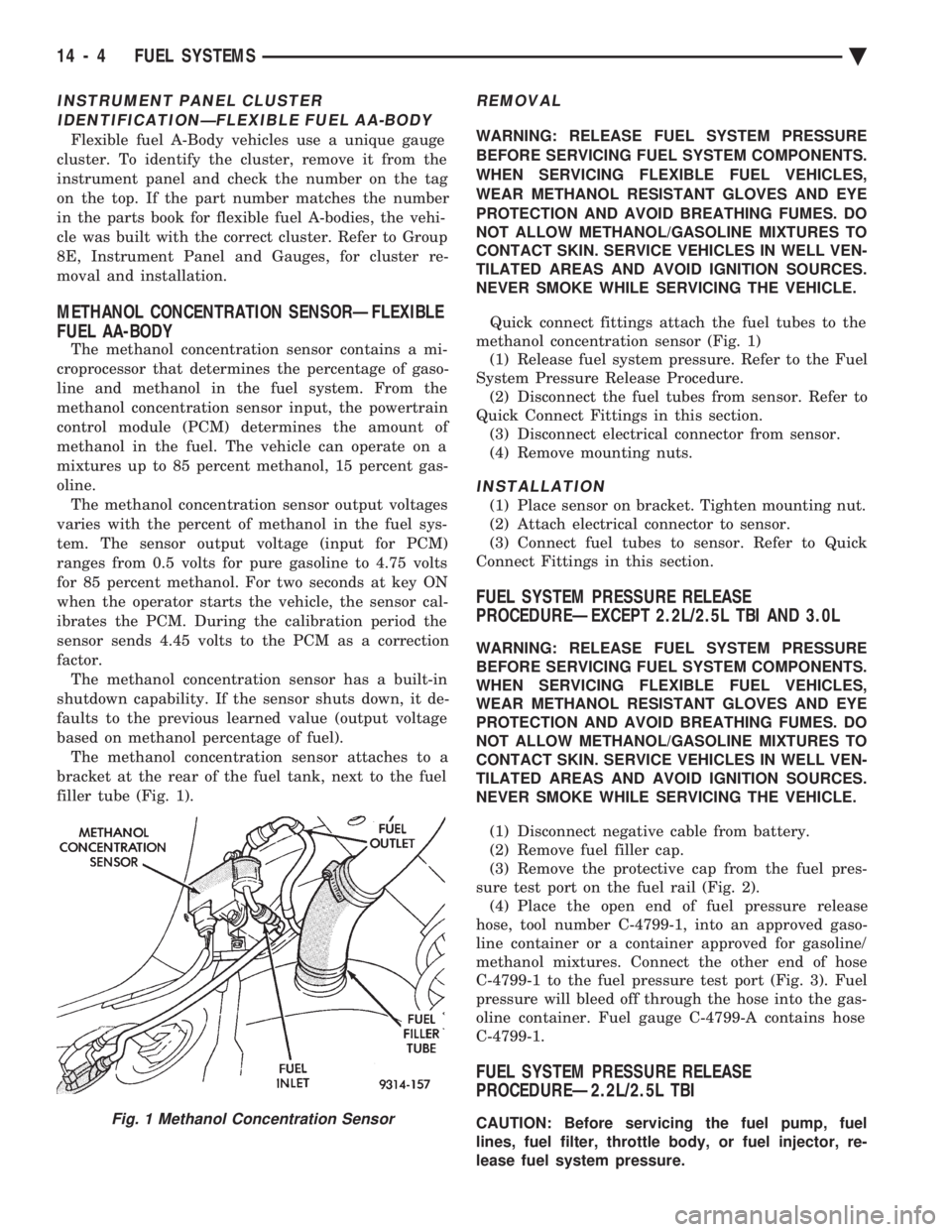
bracket at the rear of the fuel tank, next to the fuel
filler tube (Fig. 1).
REMOVAL
WARNING: RELEASE FUEL SYSTEM PRESSURE
BEFORE SERVICING FUEL SYSTEM COMPONENTS.
WHEN SERVICING FLEXIBLE FUEL VEHICLES,
WEAR METHANOL RESISTANT GLOVES AND EYE
PROTECTION AND AVOID BREATHING FUMES. DO
NOT ALLOW METHANOL/GASOLINE MIXTURES TO
CONTACT SKIN. SERVICE VEHICLES IN WELL VEN-
TILATED AREAS AND AVOID IGNITION SOURCES.
NEVER SMOKE WHILE SERVICING THE VEHICLE.
Quick connect fittings attach the fuel tubes to the
methanol concentration sensor (Fig. 1) (1) Release fuel system pressure. Refer to the Fuel
System Pressure Release Procedure. (2) Disconnect the fuel tubes from sensor. Refer to
Quick Connect Fittings in this section. (3) Disconnect electrical connector from sensor.
(4) Remove mounting nuts.
INSTALLATION
(1) Place sensor on bracket. Tighten mounting nut.
(2) Attach electrical connector to sensor.
(3) Connect fuel tubes to sensor. Refer to Quick
Connect Fittings in this section.
FUEL SYSTEM PRESSURE RELEASE
PROCEDUREÐEXCEPT 2.2L/2.5L TBI AND 3.0L
WARNING: RELEASE FUEL SYSTEM PRESSURE
BEFORE SERVICING FUEL SYSTEM COMPONENTS.
WHEN SERVICING FLEXIBLE FUEL VEHICLES,
WEAR METHANOL RESISTANT GLOVES AND EYE
PROTECTION AND AVOID BREATHING FUMES. DO
NOT ALLOW METHANOL/GASOLINE MIXTURES TO
CONTACT SKIN. SERVICE VEHICLES IN WELL VEN-
TILATED AREAS AND AVOID IGNITION SOURCES.
NEVER SMOKE WHILE SERVICING THE VEHICLE.
(1) Disconnect negative cable from battery.
(2) Remove fuel filler cap.
(3) Remove the protective cap from the fuel pres-
sure test port on the fuel rail (Fig. 2). (4) Place the open end of fuel pressure release
hose, tool number C-4799-1, into an approved gaso-
line container or a container approved for gasoline/
methanol mixtures. Connect the other end of hose
C-4799-1 to the fuel pressure test port (Fig. 3). Fuel
pressure will bleed off through the hose into the gas-
oline container. Fuel gauge C-4799-A contains hose
C-4799-1.
FUEL SYSTEM PRESSURE RELEASE
PROCEDUREÐ2.2L/2.5L TBI
CAUTION: Before servicing the fuel pump, fuel
lines, fuel filter, throttle body, or fuel injector, re-
lease fuel system pressure.Fig. 1 Methanol Concentration Sensor
14 - 4 FUEL SYSTEMS Ä
Page 1748 of 2438
CAUTION: When using the ASD Fuel System Test,
the Auto Shutdown (ASD) Relay remains energized
for either 7 minutes, until the test is stopped, or un-
til the ignition switch is turned to the Off position.
(4) Place the ignition key in the ON position. Us-
ing the DRBII scan tool, access ASD Fuel System
Test. The ASD Fuel System Test will activate the
fuel pump and pressurize the system. If the gauge reads the pressure shown in the Fuel
System Pressure chart, further testing is not re-
quired. If pressure is not correct, record the pressure
and remove gauge. If pressure is below specifications, proceed to Fuel
System Pressure Below Specifications . If pressure
is above specifications, proceed to Fuel System
Pressure Above Specifications .
Fuel System Pressure Below Specifications
If the fuel pressure reading in step (4) was below
specifications, test the system according to the fol-
lowing procedure.
WARNING: RELEASE FUEL SYSTEM PRESSURE
BEFORE DISCONNECTING A FUEL SYSTEM HOSE
OR COMPONENT.
(a) Perform Fuel Pressure Release procedure.
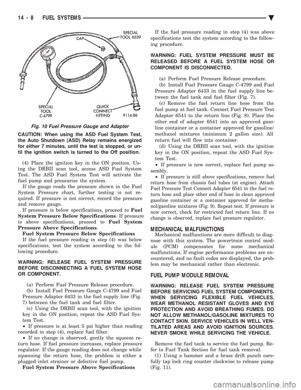
(b) Install Fuel Pressure Gauge C-4799 and Fuel
Pressure Adapter 6433 in the fuel supply line (Fig.
7) between the fuel tank and fuel filter. (c) Using the DRBII scan tool, with the ignition
key in the ON position, repeat the ASD Fuel Sys-
tem Test.
² If pressure is at least 5 psi higher than reading
recorded in step (4), replace fuel filter. ² If no change is observed, gently the squeeze re-
turn hose. If fuel pressure increases, replace pressure
regulator. If the gauge reading does not change while
squeezing the return hose, the problem is either a
plugged inlet strainer or defective fuel pump. Fuel System Pressure Above Specifications If the fuel pressure reading in step (4) was above
specifications test the system according to the follow-
ing procedure.
WARNING: FUEL SYSTEM PRESSURE MUST BE
RELEASED BEFORE A FUEL SYSTEM HOSE OR
COMPONENT IS DISCONNECTED.
(a) Perform Fuel Pressure Release procedure.
(b) Install Fuel Pressure Gauge C-4799 and Fuel
Pressure Adapter 6433 in the fuel supply line be-
tween the fuel tank and fuel filter (Fig. 7). (c) Remove the fuel return line hose from the
fuel pump at fuel tank. Connect Fuel Pressure Test
Adapter 6541 to the return line (Fig. 8). Place the
other end of adapter 6541 into an approved gaso-
line container or a container approved for gasoline/
methanol mixtures (minimum 2 gallon size). All
return fuel will flow into container. (d) Using the DRBII scan tool, with the ignition
key in the ON position, repeat the ASD Fuel Sys-
tem Test.
² If pressure is now correct, replace fuel pump as-
sembly. ²
If pressure is still above specifications, remove fuel
return hose from chassis fuel tubes (at engine). Attach
Fuel Pressure Test Connect Adapter 6541 to the fuel re-
turn hose and place other end of hose in clean approved
gasoline container or a container approved for metha-
nol/gasoline mixtures (Fig. 9). Repeat test. If pressure is
now correct, check for restricted fuel return line. If no
change is observed, replace fuel pressure regulator.
MECHANICAL MALFUNCTIONS
Mechanical malfunctions are more difficult to diag-
nose with this system. The powertrain control mod-
ule (PCM) compensates for some mechanical
malfunctions. If engine performance problems are en-
countered, and no fault codes are displayed, the prob-
lem may be mechanical rather than electronic.
FUEL PUMP MODULE REMOVAL
WARNING: RELEASE FUEL SYSTEM PRESSURE
BEFORE SERVICING FUEL SYSTEM COMPONENTS.
WHEN SERVICING FLEXIBLE FUEL VEHICLES,
WEAR METHANOL RESISTANT GLOVES AND EYE
PROTECTION AND AVOID BREATHING FUMES. DO
NOT ALLOW METHANOL/GASOLINE MIXTURES TO
CONTACT SKIN. SERVICE VEHICLES IN WELL VEN-
TILATED AREAS AND AVOID IGNITION SOURCES.
NEVER SMOKE WHILE SERVICING THE VEHICLE.
Remove the fuel tank to service the fuel pump. Re-
fer to Fuel Tank Section for fuel tank removal. (1) Using a hammer and a brass drift punch care-
fully tap lock ring counter clockwise to release pump
(Fig. 11).
Fig. 10 Fuel Pressure Gauge and Adapter
14 - 8 FUEL SYSTEMS Ä
Page 1749 of 2438
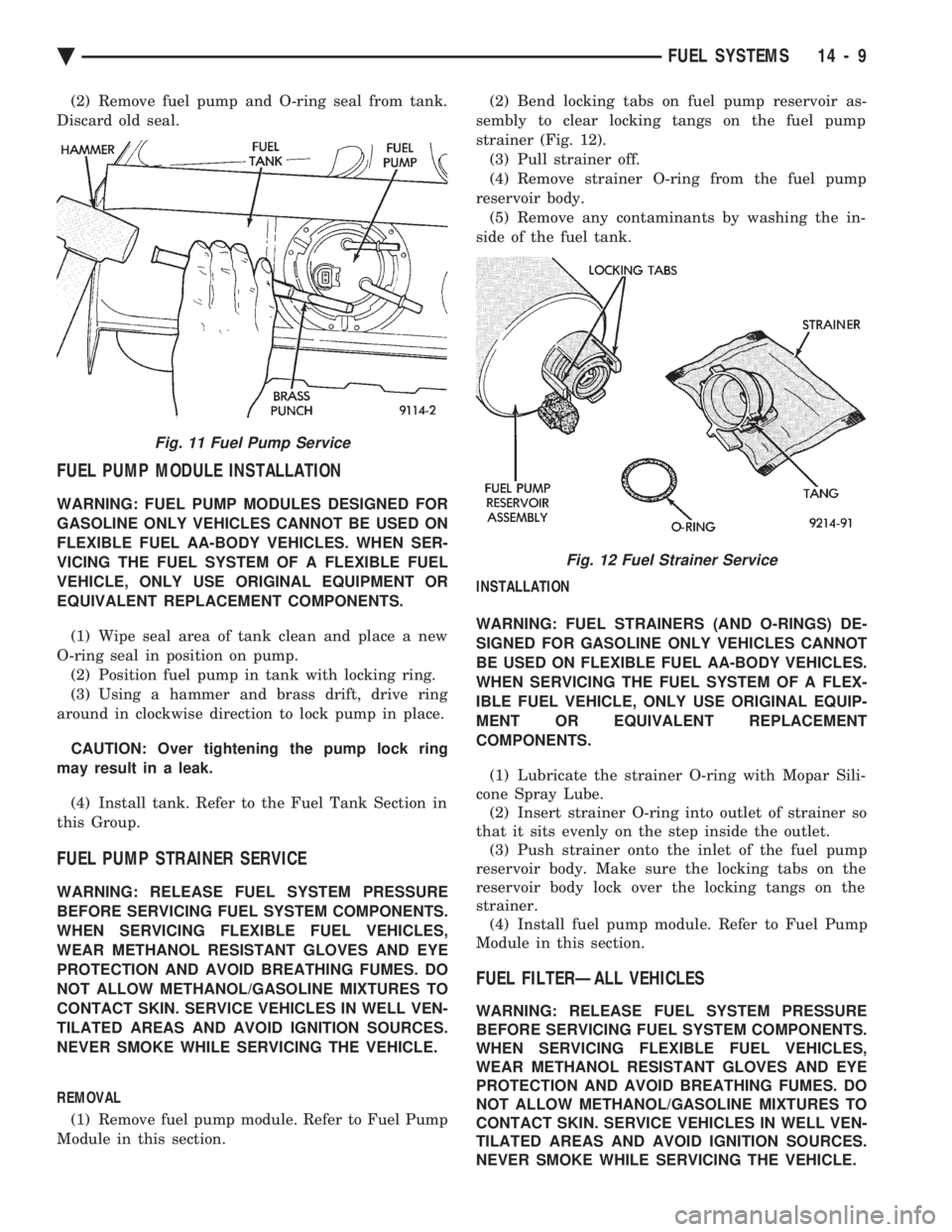
(2) Remove fuel pump and O-ring seal from tank.
Discard old seal.
FUEL PUMP MODULE INSTALLATION
WARNING: FUEL PUMP MODULES DESIGNED FOR
GASOLINE ONLY VEHICLES CANNOT BE USED ON
FLEXIBLE FUEL AA-BODY VEHICLES. WHEN SER-
VICING THE FUEL SYSTEM OF A FLEXIBLE FUEL
VEHICLE, ONLY USE ORIGINAL EQUIPMENT OR
EQUIVALENT REPLACEMENT COMPONENTS.
(1) Wipe seal area of tank clean and place a new
O-ring seal in position on pump. (2) Position fuel pump in tank with locking ring.
(3) Using a hammer and brass drift, drive ring
around in clockwise direction to lock pump in place.
CAUTION: Over tightening the pump lock ring
may result in a leak.
(4) Install tank. Refer to the Fuel Tank Section in
this Group.
FUEL PUMP STRAINER SERVICE
WARNING: RELEASE FUEL SYSTEM PRESSURE
BEFORE SERVICING FUEL SYSTEM COMPONENTS.
WHEN SERVICING FLEXIBLE FUEL VEHICLES,
WEAR METHANOL RESISTANT GLOVES AND EYE
PROTECTION AND AVOID BREATHING FUMES. DO
NOT ALLOW METHANOL/GASOLINE MIXTURES TO
CONTACT SKIN. SERVICE VEHICLES IN WELL VEN-
TILATED AREAS AND AVOID IGNITION SOURCES.
NEVER SMOKE WHILE SERVICING THE VEHICLE.
REMOVAL
(1) Remove fuel pump module. Refer to Fuel Pump
Module in this section. (2) Bend locking tabs on fuel pump reservoir as-
sembly to clear locking tangs on the fuel pump
strainer (Fig. 12). (3) Pull strainer off.
(4) Remove strainer O-ring from the fuel pump
reservoir body. (5) Remove any contaminants by washing the in-
side of the fuel tank.
INSTALLATION
WARNING: FUEL STRAINERS (AND O-RINGS) DE-
SIGNED FOR GASOLINE ONLY VEHICLES CANNOT
BE USED ON FLEXIBLE FUEL AA-BODY VEHICLES.
WHEN SERVICING THE FUEL SYSTEM OF A FLEX-
IBLE FUEL VEHICLE, ONLY USE ORIGINAL EQUIP-
MENT OR EQUIVALENT REPLACEMENT
COMPONENTS.
(1) Lubricate the strainer O-ring with Mopar Sili-
cone Spray Lube. (2) Insert strainer O-ring into outlet of strainer so
that it sits evenly on the step inside the outlet. (3) Push strainer onto the inlet of the fuel pump
reservoir body. Make sure the locking tabs on the
reservoir body lock over the locking tangs on the
strainer. (4) Install fuel pump module. Refer to Fuel Pump
Module in this section.
FUEL FILTERÐALL VEHICLES
WARNING: RELEASE FUEL SYSTEM PRESSURE
BEFORE SERVICING FUEL SYSTEM COMPONENTS.
WHEN SERVICING FLEXIBLE FUEL VEHICLES,
WEAR METHANOL RESISTANT GLOVES AND EYE
PROTECTION AND AVOID BREATHING FUMES. DO
NOT ALLOW METHANOL/GASOLINE MIXTURES TO
CONTACT SKIN. SERVICE VEHICLES IN WELL VEN-
TILATED AREAS AND AVOID IGNITION SOURCES.
NEVER SMOKE WHILE SERVICING THE VEHICLE.
Fig. 11 Fuel Pump Service
Fig. 12 Fuel Strainer Service
Ä FUEL SYSTEMS 14 - 9