light CHEVROLET DYNASTY 1993 User Guide
[x] Cancel search | Manufacturer: CHEVROLET, Model Year: 1993, Model line: DYNASTY, Model: CHEVROLET DYNASTY 1993Pages: 2438, PDF Size: 74.98 MB
Page 97 of 2438
(3) Check splined shaft and nut threads for dam-
age. (4) Inspect all 6 balls for pitting, cracks, scouring
and wear. Dulling of surface is normal. (5) Inspect cage for excessive wear on inside and
outside spherical surfaces, surface ripples on cage
window, cracks, and chipping. (6) Inspect inner race (cross) for excessivewear or
scouring of ball races. Any of the above defects will warrant replac-
ing the C/V assembly as a unit. Polished areas in races (cross and housing) and on
cage spheres are normal and do not indicate need for
joint replacement. Unless they are suspected of caus-
ing noise and vibration.
ASSEMBLE
If outer joint was not disassembled nor the
wear sleeve damaged go to step 11. (1) Position new wear sleeve on joint housing ma-
chined ledge (Fig. 1). Assemble Installer, Special Tool
C-4698 (Tool is provided with handle and dual purpose
drive head for installing wear sleeve onto C/V joint
housing and (head reversed) seal into knuckle). See
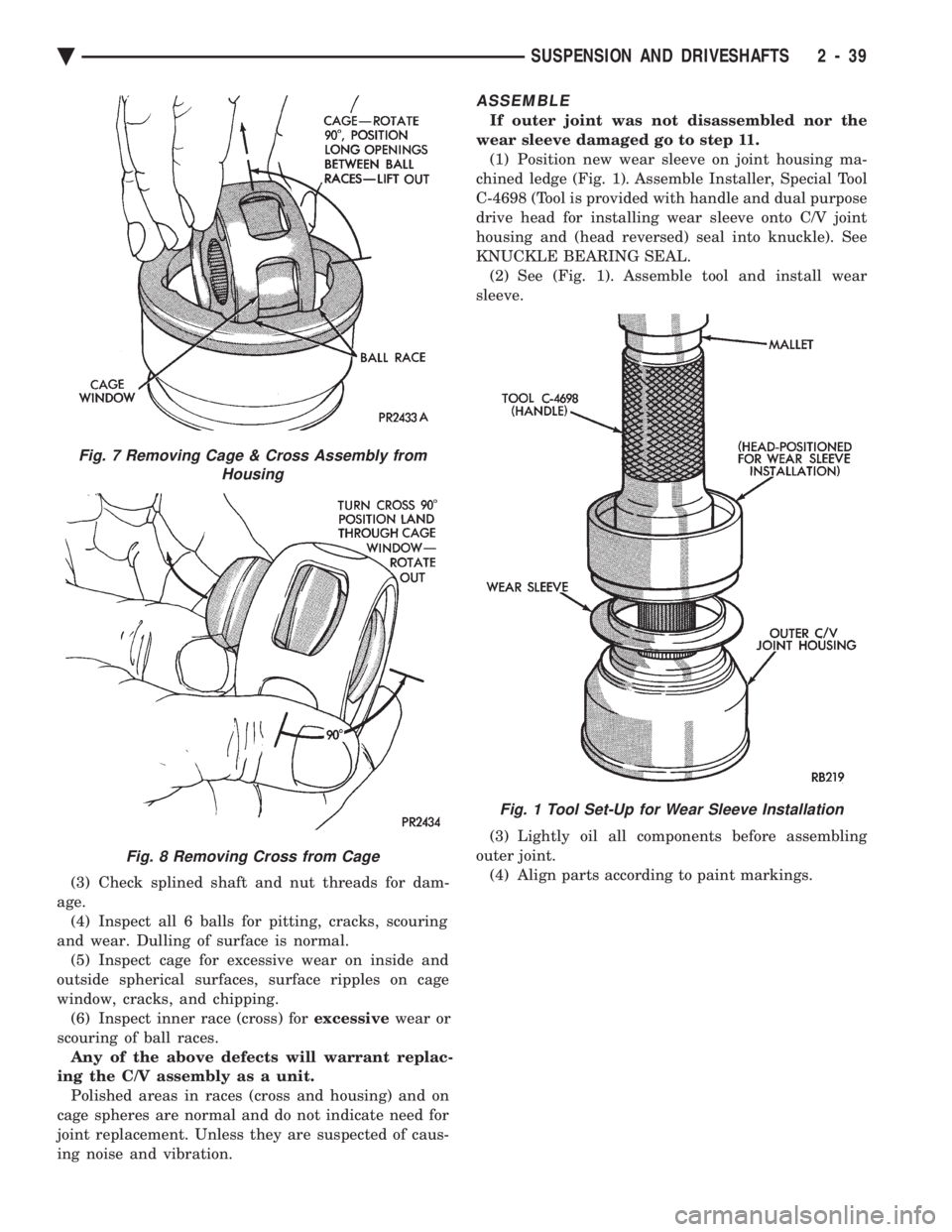
KNUCKLE BEARING SEAL. (2) See (Fig. 1). Assemble tool and install wear
sleeve.
(3) Lightly oil all components before assembling
outer joint. (4) Align parts according to paint markings.
Fig. 7 Removing Cage & Cross Assembly from Housing
Fig. 8 Removing Cross from Cage
Fig. 1 Tool Set-Up for Wear Sleeve Installation
Ä SUSPENSION AND DRIVESHAFTS 2 - 39
Page 103 of 2438
Rubber boots must be serviced with the strap and
buckle clamp. Use the Clamp Installer, Special Tool
C-4653. Proceed with the boot installation as follows: (1) Slide the small end of the boot over the shaft.
Position the boot to the edge of the locating mark or
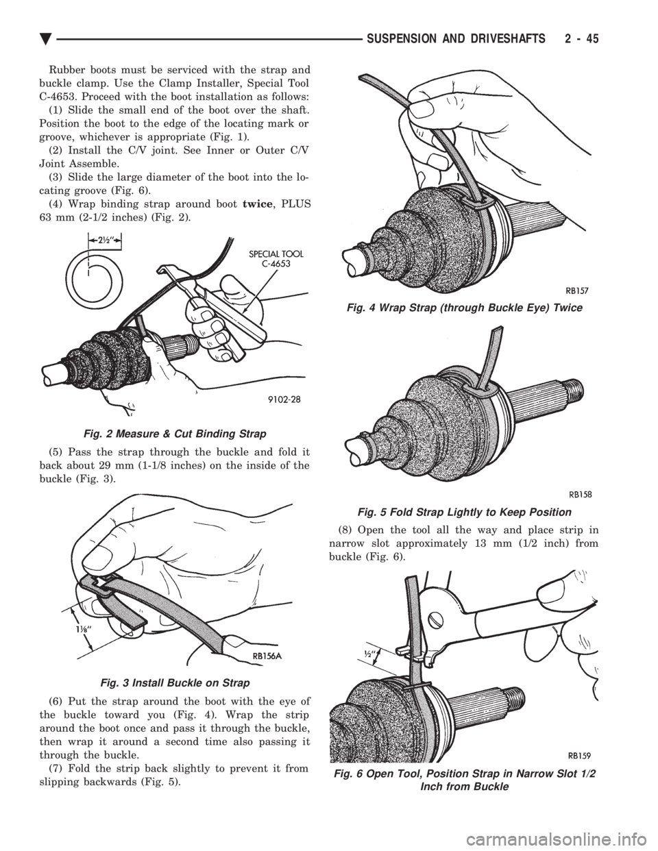
groove, whichever is appropriate (Fig. 1). (2) Install the C/V joint. See Inner or Outer C/V
Joint Assemble. (3) Slide the large diameter of the boot into the lo-
cating groove (Fig. 6). (4) Wrap binding strap around boot twice, PLUS
63 mm (2-1/2 inches) (Fig. 2).
(5) Pass the strap through the buckle and fold it
back about 29 mm (1-1/8 inches) on the inside of the
buckle (Fig. 3).
(6) Put the strap around the boot with the eye of
the buckle toward you (Fig. 4). Wrap the strip
around the boot once and pass it through the buckle,
then wrap it around a second time also passing it
through the buckle. (7) Fold the strip back slightly to prevent it from
slipping backwards (Fig. 5). (8) Open the tool all the way and place strip in
narrow slot approximately 13 mm (1/2 inch) from
buckle (Fig. 6).
Fig. 2 Measure & Cut Binding Strap
Fig. 3 Install Buckle on Strap
Fig. 4 Wrap Strap (through Buckle Eye) Twice
Fig. 5 Fold Strap Lightly to Keep Position
Fig. 6 Open Tool, Position Strap in Narrow Slot 1/2 Inch from Buckle
Ä SUSPENSION AND DRIVESHAFTS 2 - 45
Page 104 of 2438
(9) Hold the binding strip with the left hand and
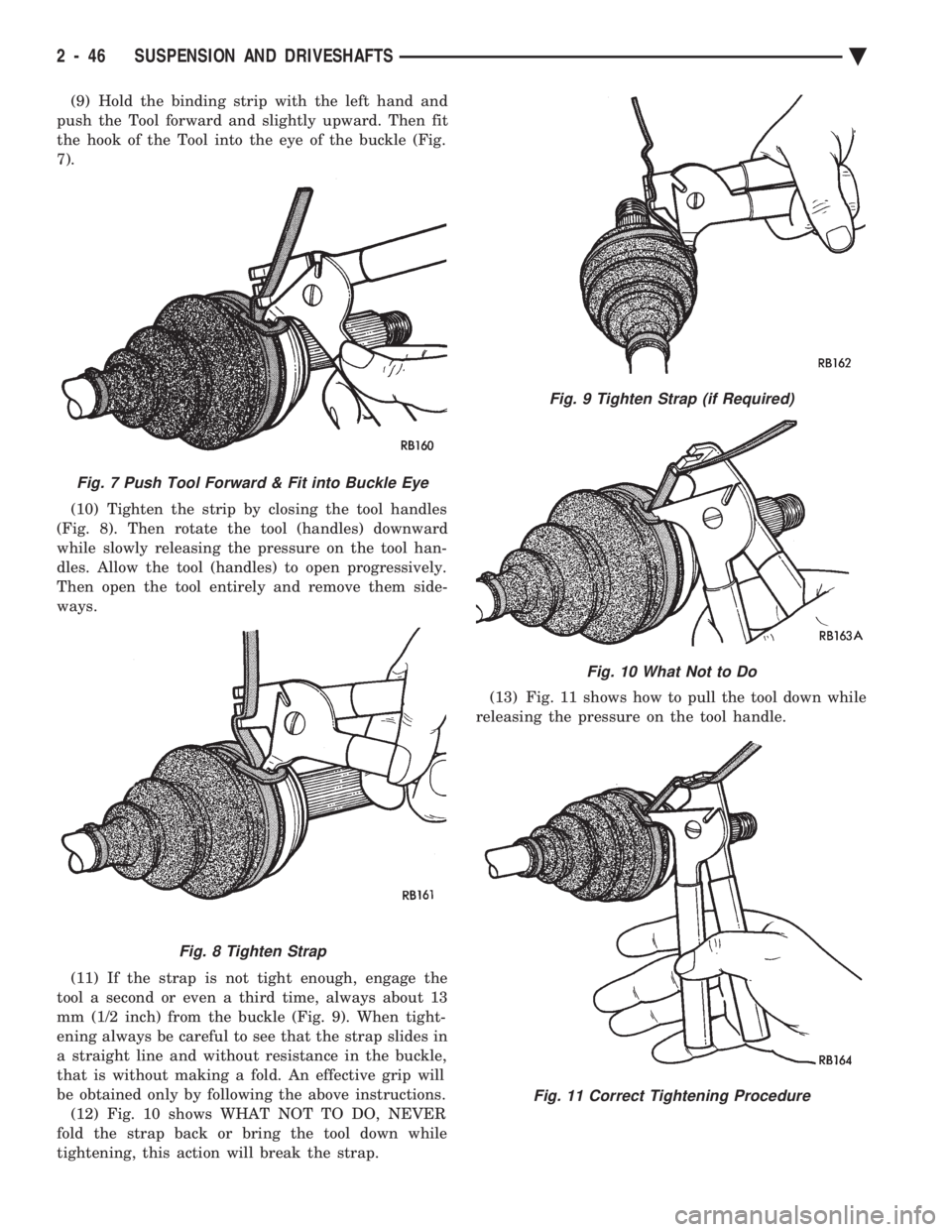
push the Tool forward and slightly upward. Then fit
the hook of the Tool into the eye of the buckle (Fig.
7).
(10) Tighten the strip by closing the tool handles
(Fig. 8). Then rotate the tool (handles) downward
while slowly releasing the pressure on the tool han-
dles. Allow the tool (handles) to open progressively.
Then open the tool entirely and remove them side-
ways.
(11) If the strap is not tight enough, engage the
tool a second or even a third time, always about 13
mm (1/2 inch) from the buckle (Fig. 9). When tight-
ening always be careful to see that the strap slides in
a straight line and without resistance in the buckle,
that is without making a fold. An effective grip will
be obtained only by following the above instructions. (12) Fig. 10 shows WHAT NOT TO DO, NEVER
fold the strap back or bring the tool down while
tightening, this action will break the strap. (13) Fig. 11 shows how to pull the tool down while
releasing the pressure on the tool handle.
Fig. 7 Push Tool Forward & Fit into Buckle Eye
Fig. 8 Tighten Strap
Fig. 9 Tighten Strap (if Required)
Fig. 10 What Not to Do
Fig. 11 Correct Tightening Procedure
2 - 46 SUSPENSION AND DRIVESHAFTS Ä
Page 109 of 2438
to the road surface. While being able to twist as one
wheel moves vertically with respect to the other.Roll resistance is provided partly by the axle's re-
sistance to twist. But primarily by a torque tube or
rod (depending on the suspension option called for)
running through the channel and attached rigidly to
its end plates by welding. Because the torque tube/
rod is an integral part of the axle assembly, it cannot
be individually replaced. The spindles are bolted to the axle end (spindle
mounting) plates and can be individually replaced if
required. Rear wheel alignment changes require the
use of shims between the spindle and axle end plates.
SHOCK ABSORBERS
REMOVAL
(1) Raise vehicle, see Hoisting, Group 0.
(2) Support axle and remove wheel and tire assem-
bly. (3) If equipped with air shocks, disconnect air
lines. (4) Remove upper and lower shock absorber fasten-
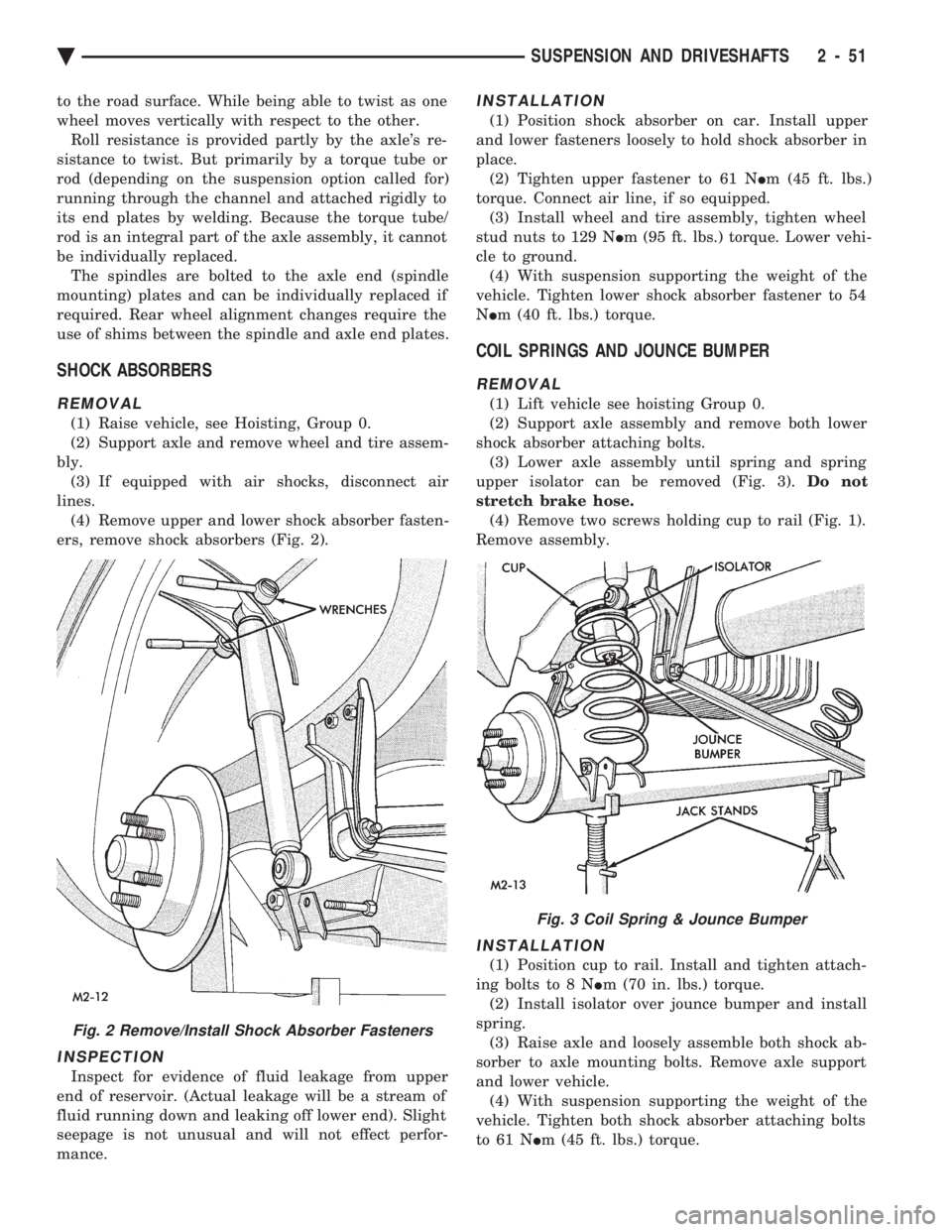
ers, remove shock absorbers (Fig. 2).
INSPECTION
Inspect for evidence of fluid leakage from upper
end of reservoir. (Actual leakage will be a stream of
fluid running down and leaking off lower end). Slight
seepage is not unusual and will not effect perfor-
mance.
INSTALLATION
(1) Position shock absorber on car. Install upper
and lower fasteners loosely to hold shock absorber in
place. (2) Tighten upper fastener to 61 N Im (45 ft. lbs.)
torque. Connect air line, if so equipped. (3) Install wheel and tire assembly, tighten wheel
stud nuts to 129 N Im (95 ft. lbs.) torque. Lower vehi-
cle to ground. (4) With suspension supporting the weight of the
vehicle. Tighten lower shock absorber fastener to 54
N Im (40 ft. lbs.) torque.
COIL SPRINGS AND JOUNCE BUMPER
REMOVAL
(1) Lift vehicle see hoisting Group 0.
(2) Support axle assembly and remove both lower
shock absorber attaching bolts. (3) Lower axle assembly until spring and spring
upper isolator can be removed (Fig. 3). Do not
stretch brake hose. (4) Remove two screws holding cup to rail (Fig. 1).
Remove assembly.
INSTALLATION
(1) Position cup to rail. Install and tighten attach-
ing bolts to 8 N Im (70 in. lbs.) torque.
(2) Install isolator over jounce bumper and install
spring. (3) Raise axle and loosely assemble both shock ab-
sorber to axle mounting bolts. Remove axle support
and lower vehicle. (4) With suspension supporting the weight of the
vehicle. Tighten both shock absorber attaching bolts
to 61 N Im (45 ft. lbs.) torque.
Fig. 2 Remove/Install Shock Absorber Fasteners
Fig. 3 Coil Spring & Jounce Bumper
Ä SUSPENSION AND DRIVESHAFTS 2 - 51
Page 111 of 2438
WARNING: WHEN REMOVING THE REAR AXLE
PIVOT BUSHING ON VEHICLES EQUIPPED WITH EI-
THER REAR COIL SPRINGS OR AIR SUSPENSION.
THE REAR AXLE MUST BE SUPPORTED BY THE
AXLE AND TRAILING ARM TO ENSURE ADEQUATE
SUPPORT OF REAR AXLE.
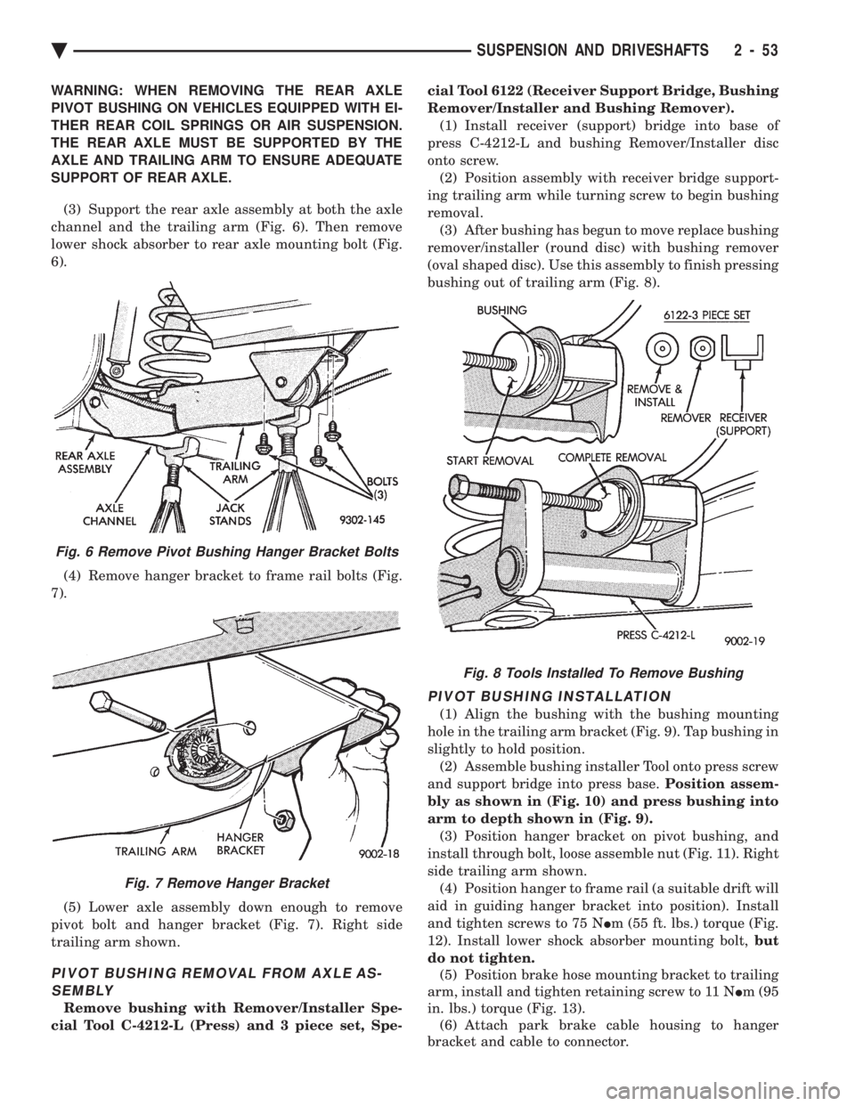
(3) Support the rear axle assembly at both the axle
channel and the trailing arm (Fig. 6). Then remove
lower shock absorber to rear axle mounting bolt (Fig.
6).
(4) Remove hanger bracket to frame rail bolts (Fig.
7).
(5) Lower axle assembly down enough to remove
pivot bolt and hanger bracket (Fig. 7). Right side
trailing arm shown.
PIVOT BUSHING REMOVAL FROM AXLE AS- SEMBLY
Remove bushing with Remover/Installer Spe-
cial Tool C-4212-L (Press) and 3 piece set, Spe- cial Tool 6122 (Receiver Support Bridge, Bushing
Remover/Installer and Bushing Remover). (1) Install receiver (support) bridge into base of
press C-4212-L and bushing Remover/Installer disc
onto screw. (2) Position assembly with receiver bridge support-
ing trailing arm while turning screw to begin bushing
removal. (3) After bushing has begun to move replace bushing
remover/installer (round disc) with bushing remover
(oval shaped disc). Use this assembly to finish pressing
bushing out of trailing arm (Fig. 8).
PIVOT BUSHING INSTALLATION
(1) Align the bushing with the bushing mounting
hole in the trailing arm bracket (Fig. 9). Tap bushing in
slightly to hold position. (2) Assemble bushing installer Tool onto press screw
and support bridge into press base. Position assem-
bly as shown in (Fig. 10) and press bushing into
arm to depth shown in (Fig. 9). (3) Position hanger bracket on pivot bushing, and
install through bolt, loose assemble nut (Fig. 11). Right
side trailing arm shown. (4) Position hanger to frame rail (a suitable drift will
aid in guiding hanger bracket into position). Install
and tighten screws to 75 N Im (55 ft. lbs.) torque (Fig.
12). Install lower shock absorber mounting bolt, but
do not tighten. (5) Position brake hose mounting bracket to trailing
arm, install and tighten retaining screw to 11 N Im (95
in. lbs.) torque (Fig. 13). (6) Attach park brake cable housing to hanger
bracket and cable to connector.
Fig. 8 Tools Installed To Remove Bushing
Fig. 6 Remove Pivot Bushing Hanger Bracket Bolts
Fig. 7 Remove Hanger Bracket
Ä SUSPENSION AND DRIVESHAFTS 2 - 53
Page 113 of 2438
PIVOT BUSHING AC AG AJ AP BODY
REMOVE FROM VEHICLE
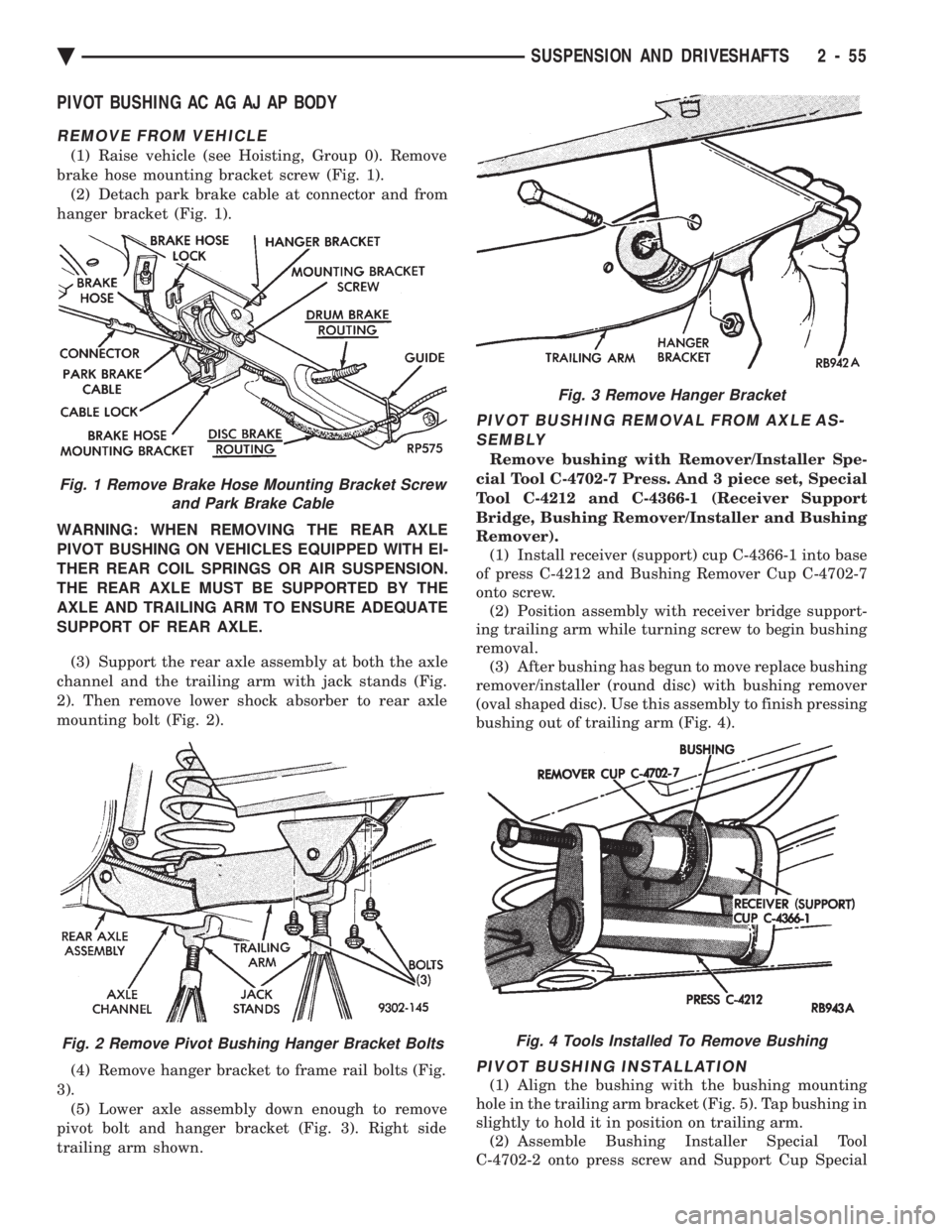
(1) Raise vehicle (see Hoisting, Group 0). Remove
brake hose mounting bracket screw (Fig. 1). (2) Detach park brake cable at connector and from
hanger bracket (Fig. 1).
WARNING: WHEN REMOVING THE REAR AXLE
PIVOT BUSHING ON VEHICLES EQUIPPED WITH EI-
THER REAR COIL SPRINGS OR AIR SUSPENSION.
THE REAR AXLE MUST BE SUPPORTED BY THE
AXLE AND TRAILING ARM TO ENSURE ADEQUATE
SUPPORT OF REAR AXLE. (3) Support the rear axle assembly at both the axle
channel and the trailing arm with jack stands (Fig.
2). Then remove lower shock absorber to rear axle
mounting bolt (Fig. 2).
(4) Remove hanger bracket to frame rail bolts (Fig.
3). (5) Lower axle assembly down enough to remove
pivot bolt and hanger bracket (Fig. 3). Right side
trailing arm shown.
PIVOT BUSHING REMOVAL FROM AXLE AS- SEMBLY
Remove bushing with Remover/Installer Spe-
cial Tool C-4702-7 Press. And 3 piece set, Special
Tool C-4212 and C-4366-1 (Receiver Support
Bridge, Bushing Remover/Installer and Bushing
Remover). (1) Install receiver (support) cup C-4366-1 into base
of press C-4212 and Bushing Remover Cup C-4702-7
onto screw. (2) Position assembly with receiver bridge support-
ing trailing arm while turning screw to begin bushing
removal. (3) After bushing has begun to move replace bushing
remover/installer (round disc) with bushing remover
(oval shaped disc). Use this assembly to finish pressing
bushing out of trailing arm (Fig. 4).
PIVOT BUSHING INSTALLATION
(1) Align the bushing with the bushing mounting
hole in the trailing arm bracket (Fig. 5). Tap bushing in
slightly to hold it in position on trailing arm. (2) Assemble Bushing Installer Special Tool
C-4702-2 onto press screw and Support Cup Special
Fig. 1 Remove Brake Hose Mounting Bracket Screw and Park Brake Cable
Fig. 2 Remove Pivot Bushing Hanger Bracket Bolts
Fig. 3 Remove Hanger Bracket
Fig. 4 Tools Installed To Remove Bushing
Ä SUSPENSION AND DRIVESHAFTS 2 - 55
Page 118 of 2438
In addition, there is an air regeneration cycle that
is controlled by the Control Module (CM). If the
height sensor signal is in the neutral or high posi-
tion. When the ignition switch is turned to the ON
position, after a 22 to 28 second delay, the compres-
sor will run from 2 to 6 seconds. To prevent excessive cycling between the compres-
sor and the exhaust solenoid circuits during normal
ride conditions. A 12 to 18 second delay is incorpo-
rated in the microprocessor.
HEIGHT SENSOR
A magnetic switch type sensor, located in the right
air shock absorber, monitors rear vehicle height. The
sensor sends signals to the (CM) relating to vehicle
rear suspension status (low, trim, high).
AIR LINES AND FITTINGS
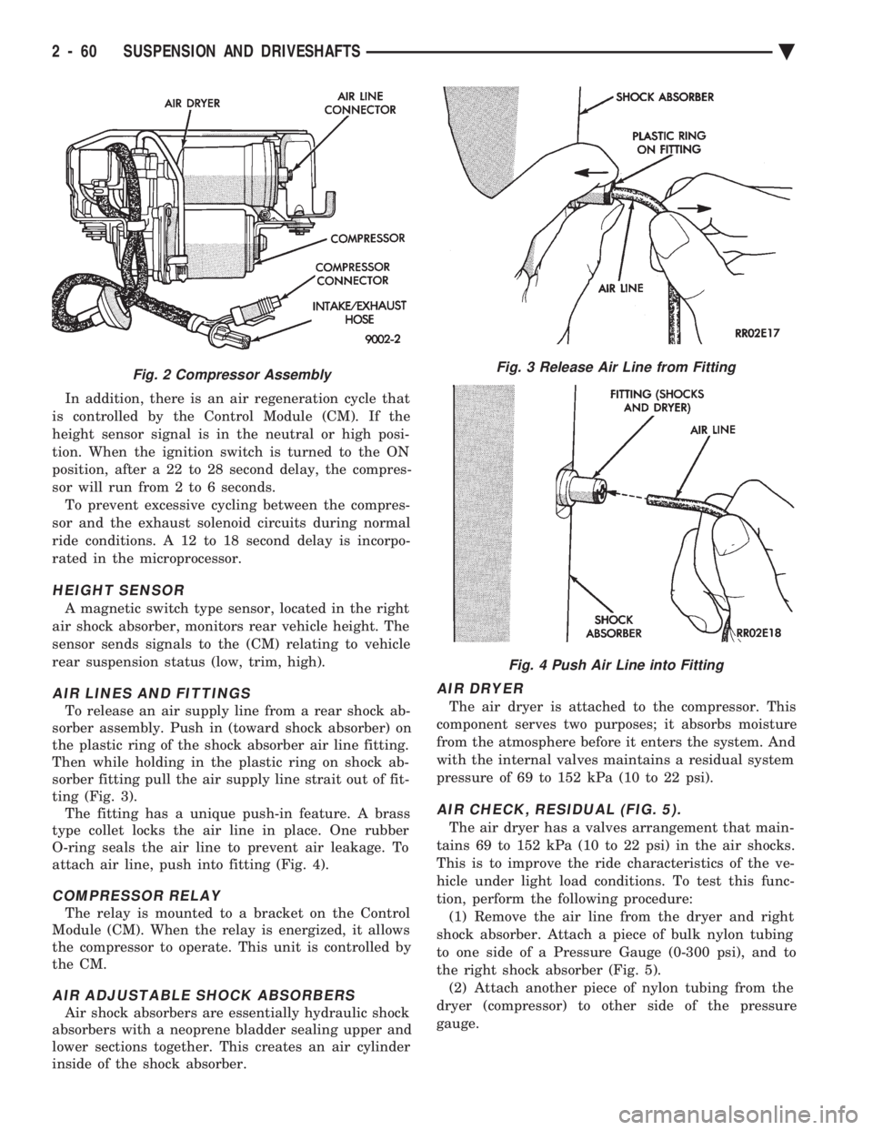
To release an air supply line from a rear shock ab-
sorber assembly. Push in (toward shock absorber) on
the plastic ring of the shock absorber air line fitting.
Then while holding in the plastic ring on shock ab-
sorber fitting pull the air supply line strait out of fit-
ting (Fig. 3). The fitting has a unique push-in feature. A brass
type collet locks the air line in place. One rubber
O-ring seals the air line to prevent air leakage. To
attach air line, push into fitting (Fig. 4).
COMPRESSOR RELAY
The relay is mounted to a bracket on the Control
Module (CM). When the relay is energized, it allows
the compressor to operate. This unit is controlled by
the CM.
AIR ADJUSTABLE SHOCK ABSORBERS
Air shock absorbers are essentially hydraulic shock
absorbers with a neoprene bladder sealing upper and
lower sections together. This creates an air cylinder
inside of the shock absorber.
AIR DRYER
The air dryer is attached to the compressor. This
component serves two purposes; it absorbs moisture
from the atmosphere before it enters the system. And
with the internal valves maintains a residual system
pressure of 69 to 152 kPa (10 to 22 psi).
AIR CHECK, RESIDUAL (FIG. 5).
The air dryer has a valves arrangement that main-
tains 69 to 152 kPa (10 to 22 psi) in the air shocks.
This is to improve the ride characteristics of the ve-
hicle under light load conditions. To test this func-
tion, perform the following procedure: (1) Remove the air line from the dryer and right
shock absorber. Attach a piece of bulk nylon tubing
to one side of a Pressure Gauge (0-300 psi), and to
the right shock absorber (Fig. 5). (2) Attach another piece of nylon tubing from the
dryer (compressor) to other side of the pressure
gauge.
Fig. 2 Compressor AssemblyFig. 3 Release Air Line from Fitting
Fig. 4 Push Air Line into Fitting
2 - 60 SUSPENSION AND DRIVESHAFTS Ä
Page 123 of 2438
REAR LEVELING DIAGNOSTIC PROCEDURES
SELF-DIAGNOSTICS
A self-diagnostic procedure is available for the ser-
vice technician to use to detect system malfunctions.
BEFORE DIAGNOSTICS TEST
Check the 20 amp fuse (position W40) and the 30
amp circuit breaker (position W5) to be assured they
are functional components. Check all connectors that link the system into the
main body wiring harness. These include compressor,
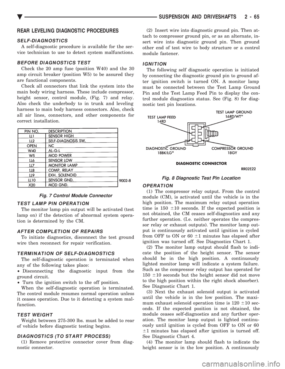
height sensor, control module, (Fig. 7) and relay.
Also check the underbody to in trunk and leveling
harness to main body harness connectors. Also, check
all air lines, connectors, and other components for
correct installation.
TEST LAMP PIN OPERATION
The monitor lamp pin output will be activated (test
lamp on) if the detection of abnormal system opera-
tion is determined by the CM.
AFTER COMPLETION OF REPAIRS
To initiate diagnostics, disconnect the test ground
wire then reconnect for repair verification.
TERMINATION OF SELF-DIAGNOSTICS
The self-diagnostic operation is terminated when
any of the following takes place:
² Disconnecting the diagnostic input from the
ground circuit.
² Turn the ignition switch to the off position.
When the self-diagnostic operation is terminated.
The control module resumes normal operation unless
it ceases operation. Due to it detecting a system mal-
function.
TEST WEIGHT
Weight between 275-300 lbs. must be added to rear
of vehicle before diagnostic testing begins.
DIAGNOSTICS (TO START PROCESS)
(1) Remove protective connector cover from diag-
nostic connector. (2) Insert wire into diagnostic ground pin. Then at-
tach to compressor ground pin, or as an alternate, in-
sert wire into diagnostic ground pin. Then ground
other end of test wire to body structure or a control
module fastener.
IGNITION
The following self diagnostic operation is initiated
by connecting the diagnostic ground pin to ground af-
ter ignition switch is turned ON. A monitor lamp
must be connected between the Test Lamp Ground
Pin and the Test Lamp Feed Pin to display the con-
trol module diagnostics status. See (Fig. 8) for diag-
nostic test pin locations.
OPERATION
(1) The compressor relay output. From the control
module (CM), is activated until the vehicle is in the
high position. The maximum relay output operation
time is 150 610 seconds. If the expected position is
not obtained, the CM ceases self-diagnostics and any
further operation. (I.e. neither operates the compres-
sor relay or exhaust outputs). The monitor lamp out-
put is continuously activated until ignition is cycled
from OFF to ON or 60 61 minutes has elapsed after
ignition was turned off. See Diagnostics Chart 1. (2) The monitor lamp output should flash to indi-
cate the position of the height sensor. The sensor
should be in the high position. A continuously
lighted monitor lamp will indicate a system failure.
Such as the compressor relay output has operated for
150 610 seconds but the height sensor did not move
to the high position within the right shock absorber).
See Diagnostic Chart 1. (3) Next the exhaust solenoid output is activated
until the vehicle is in the low position. The maxi-
mum exhaust solenoid operation time is 120 610 sec-
onds. If the expected position is not obtained, the
module ceases self-diagnostics and any further oper-
ation. The monitor lamp output is lighted continu-
ously until ignition is cycled from OFF to ON or 60
6 1 minutes has elapsed after ignition is turned off.
See Diagnostic Chart 4. (4) The monitor lamp should flash to indicate the
height sensor is in the low position. A continuouslyFig. 7 Control Module Connector
Fig. 8 Diagnostic Test Pin Location
Ä SUSPENSION AND DRIVESHAFTS 2 - 65
Page 124 of 2438
lighted monitor lamp will indicate a system failure.
Such as the exhaust solenoid operated for 120 610
seconds but the height sensor did not move to the
low position. See Diagnostic Chart 4. (5) The compressor relay output is activated to re-
turn the vehicle to the neutral (leveled) position. The
maximum operation time of the relay output is 150
6 10 seconds. If the expected position is not obtained.
The control module ceases self-diagnostics and any
further operation. The monitor lamp is continuously
lighted until the ignition is cycled from OFF to ON
or 60 61 minutes has elapsed after ignition is turned
off. The sensor will move to the neutral position. If not,
a continuously lighted monitor lamp will indicate a system failure. Such as the compressor relay output
operated for 150 610 seconds but the sensor did not
move to or sense the neutral position. See Diagnostic
Chart 1. (6) Completion of diagnostics, is when self diagnostic
procedure is successfully completed and control module
resumes normal operation. The diagnostic test is now
complete. Throughout the testing the vehicle load must
be maintained at a specific level. No loads are allowed
to be added/removed to/from the vehicle once the self
diagnosis tests have been initiated. The Diagnostic connector cover must be in-
stalled after completion of the test.
2 - 66 SUSPENSION AND DRIVESHAFTS Ä
Page 151 of 2438
BRAKES
CONTENTS
page page
ANTI-LOCK BRAKE SYSTEMÐBENDIX ANTI-LOCK 10 AC/Y BODY ............. 72
ANTI-LOCK BRAKE SYSTEMÐBENDIX ANTI-LOCK 6 AA,AG,AJ,AP BODY ....... 113
BRAKE DISC (ROTOR) ................... 53
BRAKE SUPPORT ASSEMBLY ............. 25
FRONT DISC BRAKES ................... 31
GENERAL INFORMATION .................. 1
HYDRAULIC SYSTEM CONTROL VALVES . . . 26
KELSEY HAYES DOUBLE PIN FAMILY CALIPER ............................ 35 KELSEY HAYES DOUBLE PIN NON-FAMILY
CALIPER ............................ 38
MASTER CYLINDER ..................... 66
PARKING BRAKES ...................... 57
POWER BRAKES ....................... 68
REAR DISC BRAKES .................... 45
REAR WHEEL DRUM BRAKES ............ 18
SERVICE ADJUSTMENTS .................. 4
WHEEL BEARINGS ...................... 70
WHEEL CYLINDERS ..................... 23
GENERAL INFORMATION
Throughout this group, references may be made to
a particular vehicle by letter or number designation.
A chart showing the break down of these designa-
tions is included in the Introduction Section at the
front of this service manual. Standard brake equipment consists of:
² Double pin floating caliper disc front brakes.
² Rear automatic adjusting drum brakes.
² Differential valve with a brake warning switch.
² Master cylinder.
² Vacuum power booster.
² Double pin floating caliper rear disc brakes are
available on some models. The Bendix Anti-Lock 10 braking system, uses the
standard power brake system caliper assemblies,
braking discs, pedal assembly, brake lines and hoses.
The unique parts of the Bendix Anti-Lock 10 braking
system consists of the following components. Propor-
tioning valves, wheel speed sensors, tone wheels,
electronic control unit, modulator assembly and hy-
draulic assembly. These components replace the con-
ventional master cylinder and power booster. The
components will be described in detail in the Bendix
Anti-Lock 10 brake section in this group of the ser-
vice manual. The Bendix Anti-Lock 6 braking system, uses the
following standard brake system components. Master
cylinder, power booster, caliper assemblies, braking
discs, pedal assembly, brake lines and hoses. The
unique parts of the Bendix Anti-Lock 6 braking sys-
tem consists of the following components. Modulator
assembly, unique proportioning valves, wheel speed
sensors, tone wheels, and electronic control unit.
These components will be described in detail in the
Bendix Anti-Lock 6 brake section in this group of the
service manual. The front disc brake shoes have semi-metallic lin-
ings. The hydraulic brake system (Fig .123and4)is
diagonally split on both the Non-ABS and ABS brak-
ing system. With the left front and right rear brakes
on one hydraulic system and the right front and left
rear on the other. The Non-ABS and ABS brake system may use dif-
ferent types of brake line fittings and tubing flares.
The Non-ABS brake system uses double wall tubing
flares and fittings at all tubing joint locations. Some
ABS brake systems use both ISO style tubing flares
and double wall tubing flares and corresponding fit-
tings at different joint locations. See (Figs . 2 3 and 4)
for specific joint locations and type of tubing flare. The front disc brakes consist of two different types
of caliper assemblies. A double pin Kelsey-Hayes cal-
iper (family caliper) with a bolt-on adapter attached
to the steering knuckle. Or a double pin Kelsey-
Hayes caliper (non-family caliper) which mounts di-
rectly to rails on the steering knuckle. The non-
family caliper is only used on the AY Body
(Imperials).
CAUTION: Caliper pistons, boots and seals for the
different caliper assemblies used on the front and
rear disc brake assemblies are not interchangeable.
Misusage could result in a complete brake system
failure. Be sure that the parts are replaced with the
correct replacement parts, refer to the parts book
for the type and model year of the vehicle being
worked on.
The master cylinder is anodized, lightweight alu-
minum, with a bore size of 24.0mm, 21.0mm or 7/8
inch.
Ä BRAKES 5 - 1