power steering CHEVROLET DYNASTY 1993 User Guide
[x] Cancel search | Manufacturer: CHEVROLET, Model Year: 1993, Model line: DYNASTY, Model: CHEVROLET DYNASTY 1993Pages: 2438, PDF Size: 74.98 MB
Page 254 of 2438
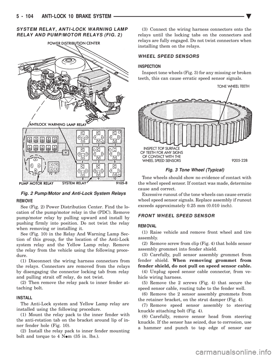
SYSTEM RELAY, ANTI-LOCK WARNING LAMP RELAY AND PUMP/MOTOR RELAYS (FIG. 2)
REMOVE
See (Fig. 2) Power Distribution Center. Find the lo-
cation of the pump/motor relay in the (PDC). Remove
pump/motor relay by pulling upward and install by
pushing firmly into position. Do not twist the relay
when removing or installing it. See (Fig. 10) in the Relay And Warning Lamp Sec-
tion of this group, for the location of the Anti-Lock
system relay and the Yellow Lamp relay. Remove
the relay from the vehicle using the following proce-
dure. (1) Disconnect the wiring harness connectors from
the relays. Connectors are removed from the relays
by disengaging the connector locking tab from relay
and pulling strait off relay, do not twist. (2) Then remove the relay pack to inner fender at-
taching bolt.
INSTALL The Anti-Lock system and Yellow Lamp relay are
installed using the following procedure. (1) Mount the relay pack to the inner fender with
the anti-rotation tab on the bracket around lip of in-
ner fender hole (Fig. 10). (2) Install the relay pack to inner fender mounting
bolt and torque to 4 N Im (35 in. lbs.). (3) Connect the wiring harness connectors onto the
relays until the locking tabs on the connectors and
relays are fully engaged. Do not twist connectors when
installing them on the relays.
WHEEL SPEED SENSORS
INSPECTION
Inspect tone wheels (Fig. 3) for any missing or broken
teeth, this can cause erratic speed sensor signals.
Tone wheels should show no evidence of contact with
the wheel speed sensor. If contact was made, determine
cause and correct. Excessive runout of the tone wheels can cause erratic
wheel speed sensor signals. Replace assembly if runout
exceeds approximately 0.25 mm (0.010 inch).
FRONT WHEEL SPEED SENSOR
REMOVAL
(1) Raise vehicle and remove front wheel and tire
assembly. (2) Remove screw from clip (Fig. 4) that holds sensor
assembly grommet into fender shield. (3) Carefully, pull sensor assembly grommet from
fender shield. When removing grommet from
fender shield, do not pull on speed sensor cable. (4) Unplug speed sensor cable connector, from ve-
hicle wiring harness. (5) Remove the 2 screws (Fig. 4) that secure the
speed sensor cable, routing tube to the fender well. (6) Remove the 2 sensor assembly grommets from
the retainer bracket, on the strut damper (Fig. 4). (7) Remove speed sensor assembly to steering
knuckle attaching bolt (Fig. 4). (8) Carefully, remove sensor head from steering
knuckle. If the sensor has seized, due to corrosion, use
a hammer and punch to tap edge of sensor ear
Fig. 2 Pump/Motor and Anti-Lock System Relays
Fig. 3 Tone Wheel (Typical)
5 - 104 ANTI-LOCK 10 BRAKE SYSTEM Ä
Page 270 of 2438
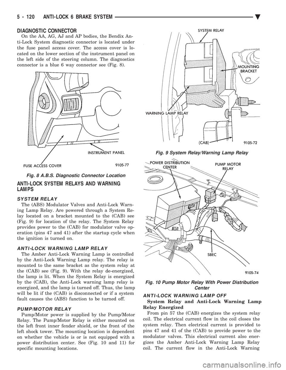
DIAGNOSTIC CONNECTOR
On the AA, AG, AJ and AP bodies, the Bendix An-
ti-Lock System diagnostic connector is located under
the fuse panel access cover. The access cover is lo-
cated on the lower section of the instrument panel on
the left side of the steering column. The diagnostics
connector is a blue 6 way connector see (Fig. 8).
ANTI-LOCK SYSTEM RELAYS AND WARNING
LAMPS
SYSTEM RELAY
The (ABS) Modulator Valves and Anti-Lock Warn-
ing Lamp Relay. Are powered through a System Re-
lay located on a bracket mounted to the (CAB) see
(Fig. 9) for location of the relay. The System Relay
provides power to the (CAB) for modulator valve op-
eration (pins 47 and 41) after the startup cycle when
the ignition is turned on.
ANTI-LOCK WARNING LAMP RELAY
The Amber Anti-Lock Warning Lamp is controlled
by the Anti-Lock Warning Lamp relay. The relay is
mounted to the same bracket as the system relay at
the (CAB) see (Fig. 9). With the relay de-energized,
the lamp is lit. When the System Relay is energized
by the (CAB), the Anti-Lock warning lamp relay is
energized, and the lamp is turned off. Thus, the lamp
will be lit if the (CAB) is disconnected or if a system
fault causes the (ABS) function to be turned off.
PUMP/MOTOR RELAY
Pump/Motor power is supplied by the Pump/Motor
Relay. The Pump/Motor Relay is either mounted on
the left front inner fender shield, or the front of the
left shock tower. The mounting location is dependent
on whether the vehicle is or is not equipped with a
power distribution center. See (Fig. 10 and 11) for
specific mounting locations.
ANTI-LOCK WARNING LAMP OFF
System Relay and Anti-Lock Warning Lamp
Relay Energized From pin 57 the (CAB) energizes the system relay
coil. The electrical current flow in the coil closes the
system relay. Then electrical current is provided to
pins 47 and 41 of the (CAB) to provide power to the
modulator valves. This electrical current also ener-
gizes the Amber Anti-Lock Warning Lamp Relay
coil. The current flow in the Anti-Lock Warning
Fig. 8 A.B.S. Diagnostic Connector Location
Fig. 9 System Relay/Warning Lamp Relay
Fig. 10 Pump Motor Relay With Power Distribution Center
5 - 120 ANTI-LOCK 6 BRAKE SYSTEM Ä
Page 282 of 2438
REMOVE/INSTALL PUMP MOTOR RELAY
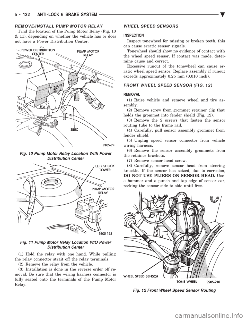
Find the location of the Pump Motor Relay (Fig. 10
& 11), depending on whether the vehicle has or does
not have a Power Distribution Center.
(1) Hold the relay with one hand. While pulling
the relay connector strait off the relay terminals. (2) Remove the relay from the vehicle.
(3) Installation is done in the reverse order off re-
moval. Be sure that the wiring harness connector is
fully seated onto the terminals of the Pump Motor
Relay.
WHEEL SPEED SENSORS
INSPECTION
Inspect tonewheel for missing or broken teeth, this
can cause erratic sensor signals. Tonewheel should show no evidence of contact with
the wheel speed sensor. If contact was made, deter-
mine cause and correct. Excessive runout of the tonewheel can cause er-
ratic wheel speed sensor. Replace assembly if runout
exceeds approximately 0.25 mm (0.010 inch).
FRONT WHEEL SPEED SENSOR (FIG. 12)
REMOVAL
(1) Raise vehicle and remove wheel and tire as-
sembly. (2) Remove screw from grommet retainer clip that
holds the grommet into fender shield (Fig. 12). (3) Remove the 2 screws that fasten the sensor
routing tube to the frame rail. (4) Carefully, pull sensor assembly grommet from
fender shield. (5) Unplug speed sensor connector from vehicle
wiring harness. (6) Remove the sensor assembly grommets from
the retainer brackets. (7) Remove sensor head screw.
(8) Carefully, remove sensor head from steering
knuckle. If the sensor has seized, due to corrosion,
DO NOT USE PLIERS ON SENSOR HEAD. Use
a hammer and a punch and tap edge of sensor ear,
rocking the sensor side to side until free.
Fig. 10 Pump Motor Relay Location With Power Distribution Center
Fig. 11 Pump Motor Relay Location W/O PowerDistribution Center
Fig. 12 Front Wheel Speed Sensor Routing
5 - 132 ANTI-LOCK 6 BRAKE SYSTEM Ä
Page 301 of 2438
ANTILOCK BRAKES OPERATION AND
PERFORMANCE
The Bendix Antilock 4 Brake System represents
the current state-of-the-art in vehicle brake systems
and offers the driver increased safety and control
during braking. This is accomplished by a sophisti-
cated system of electrical and hydraulic components.
As a result, there are a few performance characteris-
tics that may at first seem different but should be
considered normal. These characteristics are dis-
cussed below. More technical details are discussed
further in this section.
PEDAL FEEL
Since the Bendix Antilock 4 Brake System uses the
vehicle's conventional brake system power booster
and master cylinder. The brake pedal feel during
normal braking is the same as on a conventional
Non ABS equipped vehicle. When the Antilock system becomes activated dur-
ing hard braking due to a wheel lockup tendency.
The brake pedal effort will increase do to the master
cylinder pressure being isolated from the brake sys-
tem. Some brake pedal movement and associated
noises may be felt and heard by the driver. This is
normal operation of the Bendix Antilock 4 Brake
System due to pressurized brake fluid being trans-
ferred to and from the wheel brakes.
ANTILOCK BRAKE SYSTEM OPERATION
During Antilock Brake system operation, brake
pressures are modulated by cycling electric solenoid
valves. The cycling of these valves can be heard as a
series of popping or ticking noises. In addition, the
cycling may be felt as a pulsation in the brake pedal.
If Antilock operation occurs during a hard applica-
tion of the brakes, some pulsation may be felt in the
vehicle body due to fore and aft movement of vehicle
suspension components. Although ABS operation is available at virtually
all vehicle speeds, it will automatically turn off at
speeds below 3 to 5 mph. Wheel lockup may be per-
ceived at the very end of an anti lock stop and is con-
sidered normal.
TIRE NOISE & MARKS
Although the ABS system prevents complete wheel
lock-up, some wheel slip is desired in order to
achieve optimum vehicle braking performance. During brake fluid pressure modulation, as the
brake fluid pressure is increased, wheel slip is al-
lowed to reach up to 30%. This means that wheel
rolling speed is 30% less than that of a free rolling
wheel at a given vehicle speed. This slip may result
in some tire chirping, depending on the road surface.
This sound should not be interpreted as total wheel
lock-up. Complete wheel lock up normally leaves black tire
marks on dry pavement. The Antilock Brake System
will not leave dark black tire marks since the wheel
never reaches a locked condition. Tire marks may
however be noticeable as light patched marks.
VEHICLE PERFORMANCE
Antilock Brakes provide the driver with some
steering control during hard braking, however there
are conditions where the system does not provide any
benefit. In particular, hydroplaning is still possible
when the tires ride on a film of water. This results in
the vehicles tires leaving the road surface rendering
the vehicle virtually uncontrollable. In addition, ex-
treme steering maneuvers at high speed or high
speed cornering beyond the limits of tire adhesion to
the road surface may cause vehicle skidding, inde-
pendent of vehicle braking. For this reason, the ABS
system is termed Antilock instead of Anti-Skid.
SYSTEM SELF-DIAGNOSTICS
The Bendix Antilock 4 Brake System has been de-
signed with the following self diagnostic capabilities. The self diagnostic ABS startup cycle begins when
the ignition switch is turned to the on position. At
this time an electrical check is completed on the ABS
components such as Wheel Speed Sensor Continuity
and System and other Relay continuity. During this
check the Amber Antilock Light is on for approxi-
mately 1-2 seconds. Further Antilock Brake System functional testing
is accomplished once the vehicle is set in motion,
known as drive-off. (1) The solenoid valves and the pump/motor are ac-
tivated briefly to verify function.
Fig. 5 Controller Antilock Brake CAB
Ä ANTILOCK 4 BRAKE SYSTEM 5 - 15
Page 304 of 2438
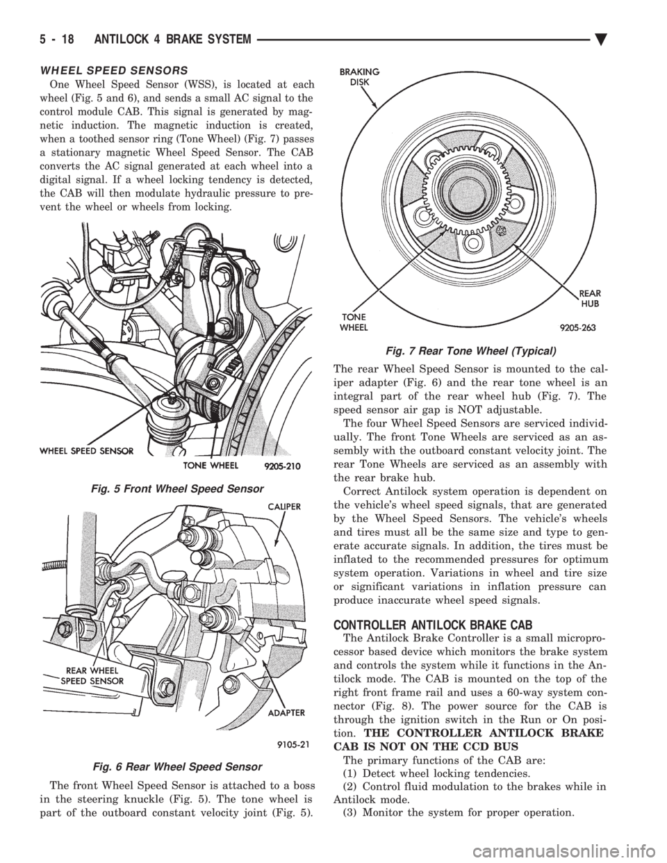
WHEEL SPEED SENSORS
One Wheel Speed Sensor (WSS), is located at each
wheel (Fig. 5 and 6), and sends a small AC signal to the
control module CAB. This signal is generated by mag-
netic induction. The magnetic induction is created,
when a toothed sensor ring (Tone Wheel) (Fig. 7) passes
a stationary magnetic Wheel Speed Sensor. The CAB
converts the AC signal generated at each wheel into a
digital signal. If a wheel locking tendency is detected,
the CAB will then modulate hydraulic pressure to pre-
vent the wheel or wheels from locking.
The front Wheel Speed Sensor is attached to a boss
in the steering knuckle (Fig. 5). The tone wheel is
part of the outboard constant velocity joint (Fig. 5). The rear Wheel Speed Sensor is mounted to the cal-
iper adapter (Fig. 6) and the rear tone wheel is an
integral part of the rear wheel hub (Fig. 7). The
speed sensor air gap is NOT adjustable.
The four Wheel Speed Sensors are serviced individ-
ually. The front Tone Wheels are serviced as an as-
sembly with the outboard constant velocity joint. The
rear Tone Wheels are serviced as an assembly with
the rear brake hub. Correct Antilock system operation is dependent on
the vehicle's wheel speed signals, that are generated
by the Wheel Speed Sensors. The vehicle's wheels
and tires must all be the same size and type to gen-
erate accurate signals. In addition, the tires must be
inflated to the recommended pressures for optimum
system operation. Variations in wheel and tire size
or significant variations in inflation pressure can
produce inaccurate wheel speed signals.
CONTROLLER ANTILOCK BRAKE CAB
The Antilock Brake Controller is a small micropro-
cessor based device which monitors the brake system
and controls the system while it functions in the An-
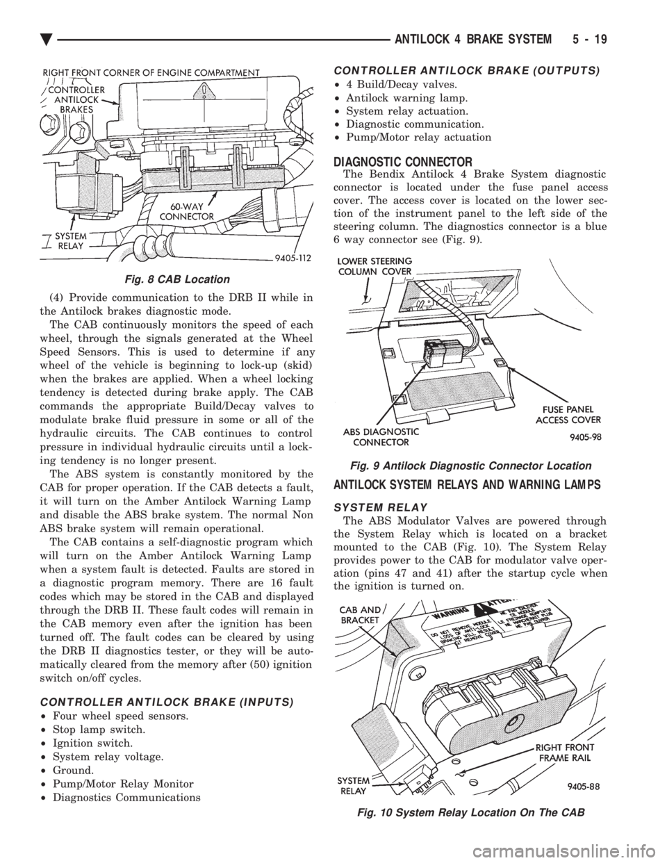
tilock mode. The CAB is mounted on the top of the
right front frame rail and uses a 60-way system con-
nector (Fig. 8). The power source for the CAB is
through the ignition switch in the Run or On posi-
tion. THE CONTROLLER ANTILOCK BRAKE
CAB IS NOT ON THE CCD BUS The primary functions of the CAB are:
(1) Detect wheel locking tendencies.
(2) Control fluid modulation to the brakes while in
Antilock mode. (3) Monitor the system for proper operation.
Fig. 5 Front Wheel Speed Sensor
Fig. 6 Rear Wheel Speed Sensor
Fig. 7 Rear Tone Wheel (Typical)
5 - 18 ANTILOCK 4 BRAKE SYSTEM Ä
Page 305 of 2438
(4) Provide communication to the DRB II while in
the Antilock brakes diagnostic mode. The CAB continuously monitors the speed of each
wheel, through the signals generated at the Wheel
Speed Sensors. This is used to determine if any
wheel of the vehicle is beginning to lock-up (skid)
when the brakes are applied. When a wheel locking
tendency is detected during brake apply. The CAB
commands the appropriate Build/Decay valves to
modulate brake fluid pressure in some or all of the
hydraulic circuits. The CAB continues to control
pressure in individual hydraulic circuits until a lock-
ing tendency is no longer present. The ABS system is constantly monitored by the
CAB for proper operation. If the CAB detects a fault,
it will turn on the Amber Antilock Warning Lamp
and disable the ABS brake system. The normal Non
ABS brake system will remain operational. The CAB contains a self-diagnostic program which
will turn on the Amber Antilock Warning Lamp
when a system fault is detected. Faults are stored in
a diagnostic program memory. There are 16 fault
codes which may be stored in the CAB and displayed
through the DRB II. These fault codes will remain in
the CAB memory even after the ignition has been
turned off. The fault codes can be cleared by using
the DRB II diagnostics tester, or they will be auto-
matically cleared from the memory after (50) ignition
switch on/off cycles.
CONTROLLER ANTILOCK BRAKE (INPUTS)
² Four wheel speed sensors.
² Stop lamp switch.
² Ignition switch.
² System relay voltage.
² Ground.
² Pump/Motor Relay Monitor
² Diagnostics Communications
CONTROLLER ANTILOCK BRAKE (OUTPUTS)
²4 Build/Decay valves.
² Antilock warning lamp.
² System relay actuation.
² Diagnostic communication.
² Pump/Motor relay actuation
DIAGNOSTIC CONNECTOR
The Bendix Antilock 4 Brake System diagnostic
connector is located under the fuse panel access
cover. The access cover is located on the lower sec-
tion of the instrument panel to the left side of the
steering column. The diagnostics connector is a blue
6 way connector see (Fig. 9).
ANTILOCK SYSTEM RELAYS AND WARNING LAMPS
SYSTEM RELAY
The ABS Modulator Valves are powered through
the System Relay which is located on a bracket
mounted to the CAB (Fig. 10). The System Relay
provides power to the CAB for modulator valve oper-
ation (pins 47 and 41) after the startup cycle when
the ignition is turned on.
Fig. 8 CAB Location
Fig. 9 Antilock Diagnostic Connector Location
Fig. 10 System Relay Location On The CAB
Ä ANTILOCK 4 BRAKE SYSTEM 5 - 19
Page 367 of 2438
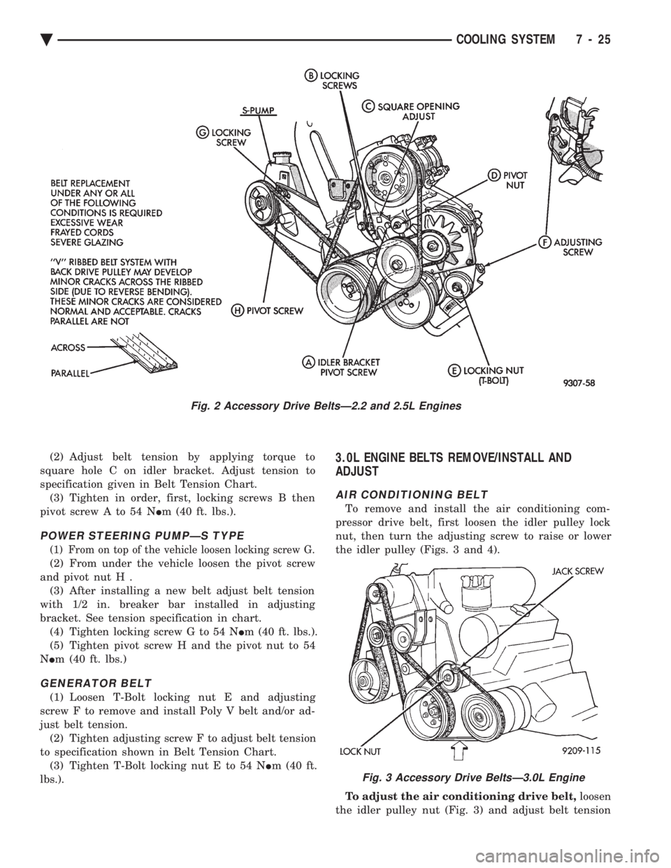
(2) Adjust belt tension by applying torque to
square hole C on idler bracket. Adjust tension to
specification given in Belt Tension Chart. (3) Tighten in order, first, locking screws B then
pivot screw A to 54 N Im (40 ft. lbs.).
POWER STEERING PUMPÐS TYPE
(1) From on top of the vehicle loosen locking screw G.
(2) From under the vehicle loosen the pivot screw
and pivot nut H . (3) After installing a new belt adjust belt tension
with 1/2 in. breaker bar installed in adjusting
bracket. See tension specification in chart. (4) Tighten locking screw G to 54 N Im (40 ft. lbs.).
(5) Tighten pivot screw H and the pivot nut to 54
N Im (40 ft. lbs.)
GENERATOR BELT
(1) Loosen T-Bolt locking nut E and adjusting
screw F to remove and install Poly V belt and/or ad-
just belt tension. (2) Tighten adjusting screw F to adjust belt tension
to specification shown in Belt Tension Chart. (3) Tighten T-Bolt locking nut E to 54 N Im (40 ft.
lbs.).
3.0L ENGINE BELTS REMOVE/INSTALL AND
ADJUST
AIR CONDITIONING BELT
To remove and install the air conditioning com-
pressor drive belt, first loosen the idler pulley lock
nut, then turn the adjusting screw to raise or lower
the idler pulley (Figs. 3 and 4).
To adjust the air conditioning drive belt, loosen
the idler pulley nut (Fig. 3) and adjust belt tension
Fig. 2 Accessory Drive BeltsÐ2.2 and 2.5L Engines
Fig. 3 Accessory Drive BeltsÐ3.0L Engine
Ä COOLING SYSTEM 7 - 25
Page 368 of 2438
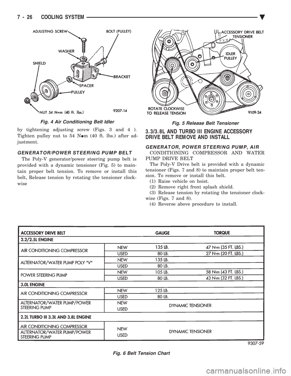
by tightening adjusting screw (Figs. 3 and 4 ).
Tighten pulley nut to 54 N Im (40 ft. lbs.) after ad-
justment.
GENERATOR/POWER STEERING PUMP BELT
The Poly-V generator/power steering pump belt is
provided with a dynamic tensioner (Fig. 5) to main-
tain proper belt tension. To remove or install this
belt, Release tension by rotating the tensioner clock-
wise
3.3/3.8L AND TURBO III ENGINE ACCESSORY
DRIVE BELT REMOVE AND INSTALL
GENERATOR, POWER STEERING PUMP, AIR
CONDITIONING COMPRESSOR AND WATER
PUMP DRIVE BELT The Poly-V Drive belt is provided with a dynamic
tensioner (Figs. 7 and 8) to maintain proper belt ten-
sion. To remove or install this belt. (1) Raise vehicle on hoist.
(2) Remove right front splash shield.
(3) Release tension by rotating the tensioner clock-
wise (Figs. 7 and 8). (4) Reverse above procedure to install.
Fig. 5 Release Belt Tensioner
Fig. 6 Belt Tension Chart
Fig. 4 Air Conditioning Belt Idler
7 - 26 COOLING SYSTEM Ä
Page 413 of 2438
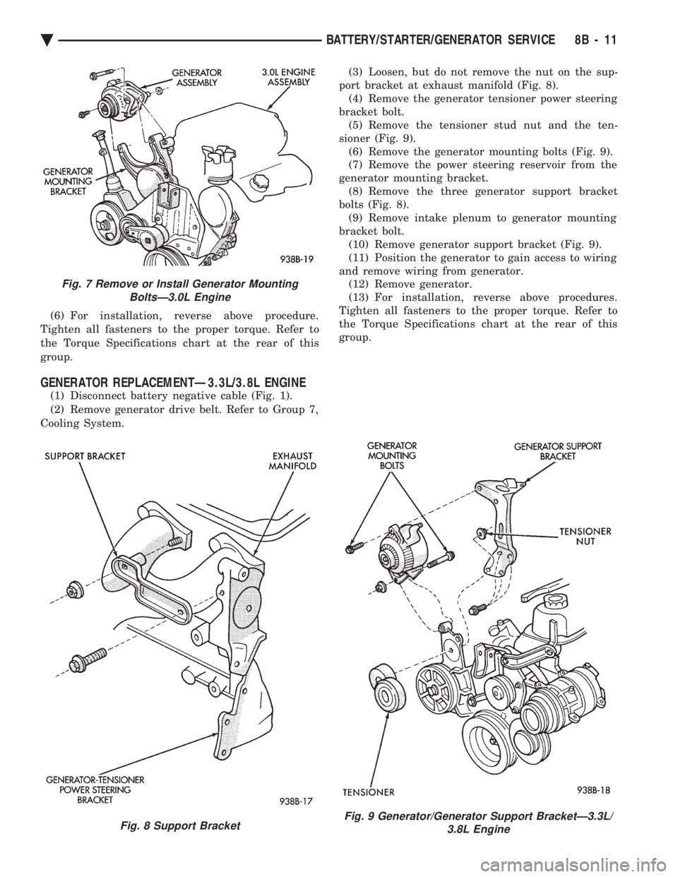
(6) For installation, reverse above procedure.
Tighten all fasteners to the proper torque. Refer to
the Torque Specifications chart at the rear of this
group.
GENERATOR REPLACEMENTÐ3.3L/3.8L ENGINE
(1) Disconnect battery negative cable (Fig. 1).
(2) Remove generator drive belt. Refer to Group 7,
Cooling System. (3) Loosen, but do not remove the nut on the sup-
port bracket at exhaust manifold (Fig. 8). (4) Remove the generator tensioner power steering
bracket bolt. (5) Remove the tensioner stud nut and the ten-
sioner (Fig. 9). (6) Remove the generator mounting bolts (Fig. 9).
(7) Remove the power steering reservoir from the
generator mounting bracket. (8) Remove the three generator support bracket
bolts (Fig. 8). (9) Remove intake plenum to generator mounting
bracket bolt. (10) Remove generator support bracket (Fig. 9).
(11) Position the generator to gain access to wiring
and remove wiring from generator. (12) Remove generator.
(13) For installation, reverse above procedures.
Tighten all fasteners to the proper torque. Refer to
the Torque Specifications chart at the rear of this
group.
Fig. 7 Remove or Install Generator Mounting BoltsÐ3.0L Engine
Fig. 8 Support BracketFig. 9 Generator/Generator Support BracketÐ3.3L/ 3.8L Engine
Ä BATTERY/STARTER/GENERATOR SERVICE 8B - 11
Page 517 of 2438
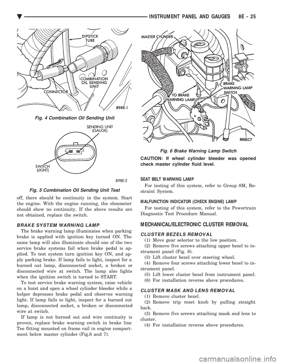
off, there should be continuity in the system. Start
the engine. With the engine running, the ohmmeter
should show no continuity. If the above results are
not obtained, replace the switch.
BRAKE SYSTEM WARNING LAMP
The brake warning lamp illuminates when parking
brake is applied with ignition key turned ON. The
same lamp will also illuminate should one of the two
service brake systems fail when brake pedal is ap-
plied. To test system turn ignition key ON, and ap-
ply parking brake. If lamp fails to light, inspect for a
burned out lamp, disconnected socket, a broken or
disconnected wire at switch. The lamp also lights
when the ignition switch is turned to START. To test service brake warning system, raise vehicle
on a hoist and open a wheel cylinder bleeder while a
helper depresses brake pedal and observes warning
light. If lamp fails to light, inspect for a burned out
lamp, disconnected socket, a broken or disconnected
wire at switch. If lamp is not burned out and wire continuity is
proven, replace brake warning switch in brake line
Tee fitting mounted on frame rail in engine compart-
ment below master cylinder (Fig.6 and 7). CAUTION: If wheel cylinder bleeder was opened
check master cylinder fluid level.
SEAT BELT WARNING LAMP
For testing of this system, refer to Group 8M, Re-
straint System.
MALFUNCTION INDICATOR (CHECK ENGINE) LAMP
For testing of this system, refer to the Powertrain
Diagnostic Test Procedure Manual.
MECHANICAL/ELECTRONIC CLUSTER REMOVAL
CLUSTER BEZELS REMOVAL
(1) Move gear selector to the low position.
(2) Remove five screws attaching upper bezel to in-
strument panel (Fig. 8). (3) Lift cluster bezel over steering wheel.
(4) Remove four screws attaching lower bezel to in-
strument panel. (5) Lift lower cluster bezel from instrument panel.
(6) For installation reverse above procedures.
CLUSTER MASK AND LENS REMOVAL
(1) Remove cluster bezel.
(2) Remove trip reset knob by pulling straight
back. (3) Remove five screws attaching mask and lens to
cluster. (4) For installation reverse above procedures.
Fig. 4 Combination Oil Sending Unit
Fig. 5 Combination Oil Sending Unit Test
Fig. 6 Brake Warning Lamp Switch
Ä INSTRUMENT PANEL AND GAUGES 8E - 25