power steering CHEVROLET DYNASTY 1993 Owner's Guide
[x] Cancel search | Manufacturer: CHEVROLET, Model Year: 1993, Model line: DYNASTY, Model: CHEVROLET DYNASTY 1993Pages: 2438, PDF Size: 74.98 MB
Page 1066 of 2438
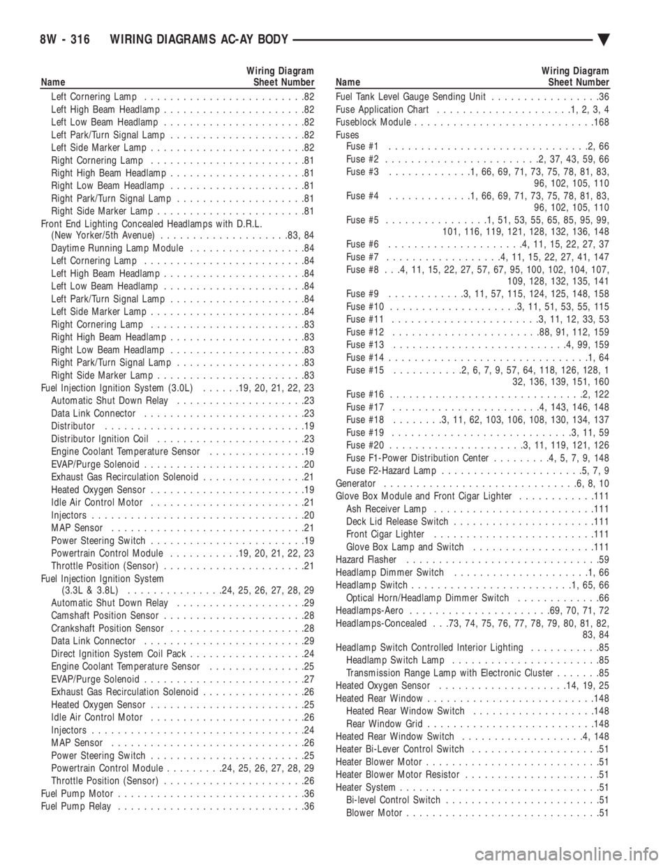
Wiring Diagram
Name Sheet Number
Left Cornering Lamp .........................82
Left High Beam Headlamp ......................82
Left Low Beam Headlamp ......................82
Left Park/Turn Signal Lamp .....................82
Left Side Marker Lamp ........................82
Right Cornering Lamp ........................81
Right High Beam Headlamp .....................81
Right Low Beam Headlamp .....................81
Right Park/Turn Signal Lamp ....................81
Right Side Marker Lamp .......................81
Front End Lighting Concealed Headlamps with D.R.L. (New Yorker/5th Avenue) ................... .83, 84
Daytime Running Lamp Module ..................84
Left Cornering Lamp .........................84
Left High Beam Headlamp ......................84
Left Low Beam Headlamp ......................84
Left Park/Turn Signal Lamp .....................84
Left Side Marker Lamp ........................84
Right Cornering Lamp ........................83
Right High Beam Headlamp .....................83
Right Low Beam Headlamp .....................83
Right Park/Turn Signal Lamp ....................83
Right Side Marker Lamp .......................83
Fuel Injection Ignition System (3.0L) ......19, 20, 21, 22, 23
Automatic Shut Down Relay ....................23
Data Link Connector .........................23
Distributor ...............................19
Distributor Ignition Coil .......................23
Engine Coolant Temperature Sensor ...............19
EVAP/Purge Solenoid .........................20
Exhaust Gas Recirculation Solenoid ................21
Heated Oxygen Sensor ........................19
Idle Air Control Motor ........................21
Injectors .................................20
MAP Sensor ..............................21
Power Steering Switch ........................19
Powertrain Control Module ...........19, 20, 21, 22, 23
Throttle Position (Sensor) ......................21
Fuel Injection Ignition System (3.3L & 3.8L) .............. .24, 25, 26, 27, 28, 29
Automatic Shut Down Relay ....................29
Camshaft Position Sensor ......................28
Crankshaft Position Sensor .....................28
Data Link Connector .........................29
Direct Ignition System Coil Pack ..................24
Engine Coolant Temperature Sensor ...............25
EVAP/Purge Solenoid .........................27
Exhaust Gas Recirculation Solenoid ................26
Heated Oxygen Sensor ........................25
Idle Air Control Motor ........................26
Injectors .................................24
MAP Sensor ..............................26
Power Steering Switch ........................25
Powertrain Control Module .........24, 25, 26, 27, 28, 29
Throttle Position (Sensor) ......................26
Fuel Pump Motor .............................36
Fuel Pump Relay .............................36Wiring Diagram
Name Sheet Number
Fuel Tank Level Gauge Sending Unit .................36
Fuse Application Chart .....................1,2,3,4
Fuseblock Module ........................... .168
Fuses Fuse #1 ...............................2,66
Fuse #2 ........................2,37,43,59,66
Fuse #3 .............1,66,69,71,73,75,78,81,83,
96, 102, 105, 110
Fuse #4 .............1,66,69,71,73,75,78,81,83,
96, 102, 105, 110
Fuse #5 ................1,51,53,55,65,85,95,99,
101, 116, 119, 121, 128, 132, 136, 148
Fuse #6 .....................4,11,15,22,27,37
Fuse #7 ..................4,11,15,22,27,41,147
Fuse #8 . . .4, 11, 15, 22, 27, 57, 67, 95, 100, 102, 104, 107, 109, 128, 132, 135, 141
Fuse #9 ............3,11,57, 115, 124, 125, 148, 158
Fuse #10 ....................3,11,51,53,55,115
Fuse #11 .......................3,11,12,33,53
Fuse #12 ...................... .88, 91, 112, 159
Fuse #13 ...........................4,99,159
Fuse #14 ...............................1,64
Fuse #15 ...........2,6,7,9,57,64, 118, 126, 128, 1
32, 136, 139, 151, 160
Fuse #16 ..............................2,122
Fuse #17 .......................4, 143, 146, 148
Fuse #18 ........3,11,62, 103, 106, 108, 130, 134, 137
Fuse #19 ............................3,11,59
Fuse #20 .....................3,11, 119, 121, 126
Fuse F1-Power Distribution Center .........4,5,7,9,148
Fuse F2-Hazard Lamp ......................5,7,9
Generator ..............................6,8,10
Glove Box Module and Front Cigar Lighter ............111
Ash Receiver Lamp ........................ .111
Deck Lid Release Switch ..................... .111
Front Cigar Lighter ........................ .111
Glove Box Lamp and Switch ...................111
Hazard Flasher ..............................59
Headlamp Dimmer Switch .....................1,66
Headlamp Switch .........................1,65,66
Optical Horn/Headlamp Dimmer Switch .............66
Headlamps-Aero ..................... .69, 70, 71, 72
Headlamps-Concealed . . .73, 74, 75, 76, 77, 78, 79, 80, 81, 82, 83, 84
Headlamp Switch Controlled Interior Lighting ...........85
Headlamp Switch Lamp .......................85
Transmission Range Lamp with Electronic Cluster .......85
Heated Oxygen Sensor ................... .14, 19, 25
Heated Rear Window ......................... .148
Heated Rear Window Switch ...................148
Rear Window Grid ......................... .148
Heated Rear Window Switch ...................4,148
Heater Bi-Lever Control Switch ....................51
Heater Blower Motor ...........................51
Heater Blower Motor Resistor .....................51
Heater System ...............................51
Bi-level Control Switch ........................51
Blower Motor ..............................51
8W - 316 WIRING DIAGRAMS AC-AY BODY Ä
Page 1068 of 2438
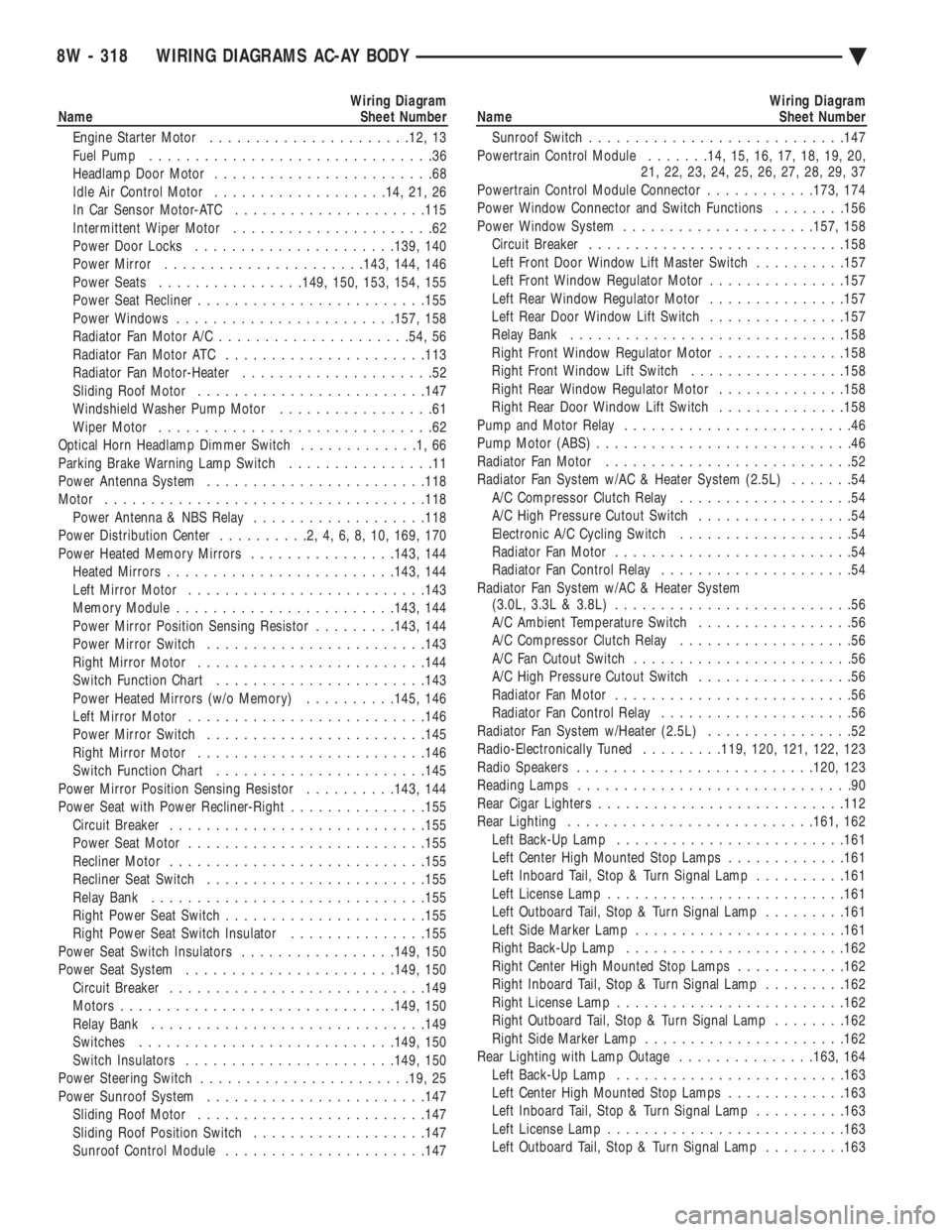
Wiring Diagram
Name Sheet Number
Engine Starter Motor ..................... .12, 13
Fuel Pump ...............................36
Headlamp Door Motor ........................68
Idle Air Control Motor .................. .14, 21, 26
In Car Sensor Motor-ATC .................... .115
Intermittent Wiper Motor ......................62
Power Door Locks ..................... .139, 140
Power Mirror ..................... .143, 144, 146
Power Seats ............... .149, 150, 153, 154, 155
Power Seat Recliner ........................ .155
Power Windows ....................... .157, 158
Radiator Fan Motor A/C .................... .54, 56
Radiator Fan Motor ATC ..................... .113
Radiator Fan Motor-Heater .....................52
Sliding Roof Motor ........................ .147
Windshield Washer Pump Motor .................61
Wiper Motor ..............................62
Optical Horn Headlamp Dimmer Switch .............1,66
Parking Brake Warning Lamp Switch ................11
Power Antenna System ....................... .118
Motor .................................. .118
Power Antenna & NBS Relay ...................118
Power Distribution Center ..........2,4,6,8,10, 169, 170
Power Heated Memory Mirrors ................143, 144
Heated Mirror s........................ .143, 144
Left Mirror Motor ......................... .143
Memory Module ....................... .143, 144
Power Mirror Position Sensing Resistor .........143, 144
Power Mirror Switch ....................... .143
Right Mirror Motor ........................ .144
Switch Function Chart ...................... .143
Power Heated Mirrors (w/o Memory) ..........145, 146
Left Mirror Motor ......................... .146
Power Mirror Switch ....................... .145
Right Mirror Motor ........................ .146
Switch Function Chart ...................... .145
Power Mirror Position Sensing Resistor ..........143, 144
Power Seat with Power Recliner-Right ...............155
Circuit Breaker ........................... .155
Power Seat Motor ......................... .155
Recliner Motor ........................... .155
Recliner Seat Switch ....................... .155
Relay Bank ............................. .155
Right Power Seat Switch ..................... .155
Right Power Seat Switch Insulator ...............155
Power Seat Switch Insulators .................149, 150
Power Seat System ...................... .149, 150
Circuit Breaker ........................... .149
Motors ............................. .149, 150
Relay Bank ............................. .149
Switches ........................... .149, 150
Switch Insulators ...................... .149, 150
Power Steering Switch ...................... .19, 25
Power Sunroof System ....................... .147
Sliding Roof Motor ........................ .147
Sliding Roof Position Switch ...................147
Sunroof Control Module ..................... .147Wiring Diagram
Name Sheet Number
Sunroof Switch ........................... .147
Powertrain Control Module .......14, 15, 16, 17, 18, 19, 20,
21, 22, 23, 24, 25, 26, 27, 28, 29, 37
Powertrain Control Module Connector ............173, 174
Power Window Connector and Switch Functions ........156
Power Window System .................... .157, 158
Circuit Breaker ........................... .158
Left Front Door Window Lift Master Switch ..........157
Left Front Window Regulator Motor ...............157
Left Rear Window Regulator Motor ...............157
Left Rear Door Window Lift Switch ...............157
Relay Bank ............................. .158
Right Front Window Regulator Motor ..............158
Right Front Window Lift Switch .................158
Right Rear Window Regulator Motor ..............158
Right Rear Door Window Lift Switch ..............158
Pump and Motor Relay .........................46
Pump Motor (ABS) ............................46
Radiator Fan Motor ...........................52
Radiator Fan System w/AC & Heater System (2.5L) .......54
A/C Compressor Clutch Relay ...................54
A/C High Pressure Cutout Switch .................54
Electronic A/C Cycling Switch ...................54
Radiator Fan Motor ..........................54
Radiator Fan Control Relay .....................54
Radiator Fan System w/AC & Heater System (3.0L, 3.3L & 3.8L) ..........................56
A/C Ambient Temperature Switch .................56
A/C Compressor Clutch Relay ...................56
A/C Fan Cutout Switch ........................56
A/C High Pressure Cutout Switch .................56
Radiator Fan Motor ..........................56
Radiator Fan Control Relay .....................56
Radiator Fan System w/Heater (2.5L) ................52
Radio-Electronically Tuned .........119, 120, 121, 122, 123
Radio Speakers ......................... .120, 123
Reading Lamps ..............................90
Rear Cigar Lighters .......................... .112
Rear Lighting .......................... .161, 162
Left Back-Up Lamp ........................ .161
Left Center High Mounted Stop Lamps .............161
Left Inboard Tail, Stop & Turn Signal Lamp ..........161
Left License Lamp ......................... .161
Left Outboard Tail, Stop & Turn Signal Lamp .........161
Left Side Marker Lamp ...................... .161
Right Back-Up Lamp ....................... .162
Right Center High Mounted Stop Lamps ............162
Right Inboard Tail, Stop & Turn Signal Lamp .........162
Right License Lamp ........................ .162
Right Outboard Tail, Stop & Turn Signal Lamp ........162
Right Side Marker Lamp ..................... .162
Rear Lighting with Lamp Outage ...............163, 164
Left Back-Up Lamp ........................ .163
Left Center High Mounted Stop Lamps .............163
Left Inboard Tail, Stop & Turn Signal Lamp ..........163
Left License Lamp ......................... .163
Left Outboard Tail, Stop & Turn Signal Lamp .........163
8W - 318 WIRING DIAGRAMS AC-AY BODY Ä
Page 1071 of 2438
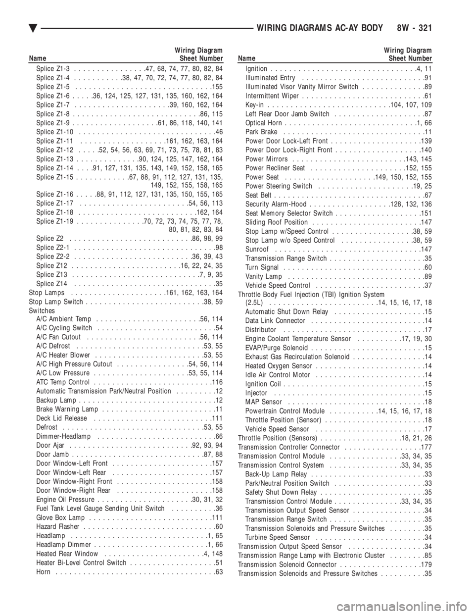
Wiring Diagram
Name Sheet Number
Splice Z1-3 ............... .47, 68, 74, 77, 80, 82, 84
Splice Z1-4 .......... .38, 47, 70, 72, 74, 77, 80, 82, 84
Splice Z1-5 ............................. .155
Splice Z1-6 .....36, 124, 125, 127, 131, 135, 160, 162, 164
Splice Z1-7 .................... .39, 160, 162, 164
Splice Z1-8 ........................... .86, 115
Splice Z1-9 .................. .61, 86, 118, 140, 141
Splice Z1-10 ..............................46
Splice Z1-11 .................. .161, 162, 163, 164
Splice Z1-12 .....52, 54, 56, 63, 69, 71, 73, 75, 78, 81, 83
Splice Z1-13 ............. .90, 124, 125, 147, 162, 164
Splice Z1-14 . . . .91, 127, 131, 135, 143, 149, 152, 158, 165
Splice Z1-15 ........... .67, 88, 91, 112, 127, 131, 135,
149, 152, 155, 158, 165
Splice Z1-16 .....88, 91, 112, 127, 131, 135, 150, 155, 165
Splice Z1-17 ....................... .54, 56, 113
Splice Z1-18 ......................... .162, 164
Splice Z1-19 .............. .70, 72, 73, 74, 75, 77, 78,
80, 81, 82, 83, 84
Splice Z2 .......................... .86, 98, 99
Splice Z2-1 ...............................98
Splice Z2-2 ......................... .36, 39, 43
Splice Z12 ....................... .16, 22, 24, 35
Splice Z13 ............................7,9,35
Splice Z14 ...............................35
Stop Lamps .................... .161, 162, 163, 164
Stop Lamp Switch ......................... .38, 59
Switches A/C Ambient Temp ...................... .56, 114
A/C Cycling Switch ..........................54
A/C Fan Cutout ........................ .56, 114
A/C Defrost ........................... .53, 55
A/C Heater Blower ....................... .53, 55
A/C High Pressure Cutout ................54, 56, 114
A/C Low Pressure .................... .53, 55, 114
ATC Temp Control ......................... .116
Automatic Transmission Park/Neutral Position .........12
Backup Lamp ..............................12
Brake Warning Lamp .........................11
Deck Lid Release ......................... .111
Defrost .............................. .53, 55
Dimmer-Headlamp ..........................66
Door Ajar .......................... .92, 93, 94
Door Jamb ............................ .87, 88
Door Window-Left Front ..................... .157
Door Window-Left Rear ..................... .157
Door Window-Right Front .................... .158
Door Window-Right Rear .................... .158
Engine Oil Pressure .................... .30, 31, 32
Fuel Tank Level Gauge Sending Unit Switch ..........36
Glove Box Lamp .......................... .111
Hazard Flasher .............................60
Headlamp ..............................1,65
Headlamp Dimmer .........................1,66
Heated Rear Window ......................4,148
Heater Bi-Level Control Switch ...................51
Horn ...................................63Wiring Diagram
Name Sheet Number
Ignition ................................4,11
Illuminated Entry ...........................91
Illuminated Visor Vanity Mirror Switch ..............89
Intermittent Wiper ...........................61
Key-in .......................... .104, 107, 109
Left Rear Door Jamb Switch ....................87
Optical Horn .............................1,66
Park Brake ...............................11
Power Door Lock-Left Front ................... .139
Power Door Lock-Right Front ...................140
Power Mirrors ........................ .143, 145
Power Recliner Seat .................... .152, 155
Power Seat ................... .149, 150, 152, 155
Power Steering Switch .................... .19, 25
Seat Belt .................................67
Security Alarm-Hood ................. .128, 132, 136
Seat Memory Selector Switch ...................151
Sliding Roof Position ....................... .147
Stop Lamp w/Speed Control ..................38, 59
Stop Lamp w/o Speed Control ................38, 59
Sunroof ............................... .147
Transmission Range Switch .....................35
Turn Signal ...............................60
Vanity Lamp ..............................89
Vehicle Speed Control ........................37
Throttle Body Fuel Injection (TBI) Ignition System (2.5L) ....................... .14, 15, 16, 17, 18
Automatic Shut Down Relay ....................15
Data Link Connector .........................14
Distributor ...............................17
Engine Coolant Temperature Sensor ..........17, 19, 30
EVAP/Purge Solenoid .........................15
Exhaust Gas Recirculation Solenoid ................14
Heated Oxygen Sensor ........................14
Idle Air Control Motor ........................14
Ignition Coil ...............................15
Injector .................................15
MAP Sensor ..............................18
Powertrain Control Module ...........14, 15, 16, 17, 18
Throttle Position (Sensor) ......................18
Vehicle Speed Sensor ........................17
Throttle Position (Sensors) ..................18, 21, 26
Transmission Controller Connector .................177
Transmission Control Module ................33, 34, 35
Transmission Control System ................33, 34, 35
Back-Up Lamp Relay .........................33
Park/Neutral Position Switch ....................33
Safety Shut Down Relay .......................35
Transmission Control Module ...............33, 34, 35
Transmission Output Speed Sensor ................34
Transmission Range Switch .....................35
Transmission Solenoids and Pressure Switches ........35
Turbine Speed Sensor ........................34
Transmission Output Speed Sensor .................34
Transmission Range Lamp with Electronic Cluster ........85
Transmission Solenoid Connector ..................179
Transmission Solenoids and Pressure Switches ..........35
Ä WIRING DIAGRAMS AC-AY BODY 8W - 321
Page 1468 of 2438
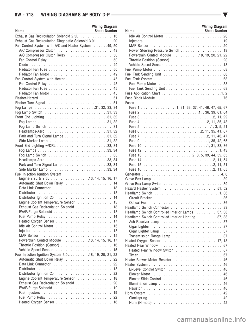
Wiring Diagram
Name Sheet Number
Exhaust Gas Recirculation Solenoid 2.5L ..............13
Exhaust Gas Recirculation Diagnostic Solenoid 3.0L. ......20
Fan Control System with A/C and Heater System ......49, 50
A/C Compressor Clutch .......................49
A/C Compressor Clutch Relay ...................50
Fan Control Relay ...........................50
Diode ...................................49
Radiator Fan Fuse ...........................50
Radiator Fan Motor ..........................49
Fan Control System with Heater ....................45
Fan Control Relay ...........................45
Radiator Fan Fuse ...........................45
Radiator Fan Motor ..........................45
Flasher-Hazard ..............................51
Flasher-Turn Signal ............................51
Fog Lamps ........................ .31, 32, 33, 34
Fog Lamp Switch ......................... .31, 33
Front End Lighting ........................ .31, 32
Fog Lamps ............................ .31, 32
Fog Lamp Switch ...........................31
Headlamps-Aero ........................ .31, 32
Park and Turn Signal Lamps ..................31, 32
Side Marker Lamp ....................... .31, 32
Front End Lighting w/DRL .................... .33, 34
Fog Lamps ............................ .33, 34
Fog Lamp Switch ...........................33
Headlamps-Aero ........................ .33, 34
Park and Turn Signal Lamps ..................33, 34
Side Marker Lamp ....................... .33, 34
Fuel Injection Ignition System Engine 2.2L & 2.5L ............... .13, 14, 15, 16, 17
Automatic Shut Down Relay ....................14
Data Link Connector .........................13
Distributor ...............................15
Distributor Ignition Coil .......................14
Engine Coolant Temperature Sensor ...............15
Exhaust Gas Recirculation Solenoid ................13
EVAP/Purge Solenoid .........................13
Fuel Pump Relay ...........................14
Heated Oxygen Sensor ........................17
Idle Air Control Motor ........................16
Injector .................................13
MAP Sensor ..............................15
Powertrain Control Module ...........13, 14, 15, 16, 17
Throttle Position (Sensor) ......................16
Vehicle Speed Sensor ........................15
Fuel Injection Ignition System 3.0L ........18, 19, 20, 21, 22
Automatic Shut Down Relay ....................22
Data Link Connector .........................22
Distributor ...............................18
Distributor Ignition Coil .......................22
Engine Coolant Temperature Sensor ...............18
Exhaust Gas Recirculation Solenoid ................20
EVAP/Purge Solenoid .........................19
Fuel Injectors ..............................19
Fuel Pump Relay ...........................22
Heated Oxygen Sensor ........................18Wiring Diagram
Name Sheet Number
Idle Air Control Motor ........................20
Injectors .................................19
MAP Sensor ..............................20
Power Steering Pressure Switch ..................19
Powertrain Control Module ...........18, 19, 20, 21, 22
Throttle Position (Sensor) ......................20
Vehicle Speed Sensor ........................18
Fuel Pump Motor .............................68
Fuel Tank Sending Unit .........................68
Fuel Tank System .............................68
Fuel Pump Motor ...........................58
Fuel Tank Sending Unit ........................68
Fuse Application Char t.........................1,2
Fuse Block Module ............................76
Fuses Fuse 1 ...............1,31,33,37,41,46,47,65,67
Fuse 2 ........................1,,36,39,61,64
Fuse 3 ..............................2,11,29
Fuse 4 ...........................2,11,35,43
Fuse 5 .............................1,3,5,51
Fuse 6 .........................2,11,35,41,67
Fuse 7 ...........................2,11,46,47
Fuse 9 ...........................1,35,42,65
Fuse 10 ..........................1,31,33,36
Fuse 12 ...............................1,43
Fuse 13 ....................2,3,5,39,44,55,65
Fuse 14 .............................2,11,54
Fuse 15 .............................2,11,51
Fuse 16 .............................2,11,65
Generator .................................4,6
Glove Box Lamp .............................39
Glove Box Lamp Switch .........................39
Hazard Flasher System ...................... .51, 52
Headlamp Switch ...........................1,36
Circuit Breaker .............................36
Optical Horn ..............................36
Headlamp Switch Connector ......................83
Headlamp Switch Controlled Interior Lamps .........37, 38
Headlamp Switch Controlled Interior Lighting .........37, 38
Ash Receiver Lamp ..........................37
Cigar Lighter ..............................37
Cigar Lighter Lamp ..........................37
Transmission Range Lamp .....................37
Heated Oxygen Sensor ...................... .17, 18
Heated Rear Window ..........................67
Heated Rear Window Switch ....................67
Timer ...................................67
Heater Blower Motor Resistor .....................46
Heater System ...............................46
Bi-Level Control Switch .......................46
Blower Motor ..............................46
Blower Slide Control .........................46
Illumination Lamp ...........................46
Resistor .................................46
Horn System ...............................42
Clockspring ...............................42
Horn (Hi-note) .............................42
8W - 718 WIRING DIAGRAMS AP BODY D-P Ä
Page 1471 of 2438
Wiring Diagram
Name Sheet Number
Splice M1-3 ........................... .40, 55
Splice M2-1 ...............................39
Splice P33 ............................ .62, 64
Splice P34 ............................ .62, 64
Splice Q1 ................................58
Splice T13 ...............................24
Splice T16 ...............................25
Splice T41 ...............................23
Splice T41-1 ............................9,10
Splice X2 ................................42
Splice X2-1 ...............................42
Splice X13 ...............................66
Splice X15 ...............................66
Splice Z0 .................................3
Splice Z0-1 ...............................14
Splice Z0-2 ...............................21
Splice Z1 ......... .40, 44, 55, 57, 60, 61, 63, 68, 69, 71
Splice Z1-1 ...................... .38, 46, 47, 66
Splice Z1-2 ......................... .31, 33, 42
Splice Z1-3 ......................... .32, 34, 42
Splice Z1-4 ............7,27,28,29,32,34,42,45,49
Splice Z1-5 .................... .55, 57, 60, 61, 63
Splice Z1-6 ...............................38
Splice Z1-7 ........................... .70, 72
Splice Z1-8 ........................... .67, 70
Splice Z1-10 ........................... .32, 34
Splice Z1-11 ........................ .32, 34, 42
Splice Z1-12 .............. .55, 57, 60, 61, 63, 69, 71
Splice Z1-14 ........................... .27, 28
Splice Z2 ................................38
Splice Z12 ............................ .14, 21
Splice Z13 ...............................25
Splice Z14 ...............................25
Steering Column Connectors ......................81
Steering Multi-Function Switch Column Connectors .......82
Stereo Radio ................................65
Stop Lamp System ............................29
Stop Lamp Switch ............................29
Switches A/C Cycling Clutch Switch ......................48
A/C Switch ...............................47
A/C Heater Blower Switch ......................47
A/C High Pressure Switch ......................48
A/C Low Pressure Switch ......................48
Back-Up Lamp Switch .....................7,8,9
Blower Switch-A/C Heater ......................47
Brake Warning Lamp Switch ....................11
Clutch Pedal Position Switch ...................7,9
Defrost Switch .............................47
Door Lock Switch (2-dr) ................... .61, 62
Door Lock Switch (4-dr) ................... .63, 64
Door Jamb Switch ....................... .39, 40
Dual Mirror Control Switch .....................55
Engine Oil Pressure Switch .....................12
Fog Lamp Switch ........................ .31, 33
Glove Box Lamp Switch .......................39
Hazard Flasher Switch ........................52Wiring Diagram
Name Sheet Number
Headlamp Switch .........................1,36
Heated Rear Window Switch ....................67
Heater Bi-level Control Switch ...................46
Horn Switch ..............................42
Ignition Switch ...........................2,11
Liftgate Latch Switch .........................40
Mercury Switch ............................12
Park Brake Switch ...........................11
Park/Neutral Position Switch .....................8
Park/Neutral Start Switch ......................23
Power Mirrors Switch ........................55
Power Seat Switch ..........................60
Power Steering Pressure Switch ..................19
Power Window Switch (2 Dr) ...................57
Power Window Switch (4 Dr) ...................58
Seat Belt Warning Switch ......................44
Speed Control Switch ........................29
Stop Lamp Switch ..........................29
Transmission Range Switch .....................25
Transmission Solenoids and Pressure Switch ..........25
Turn Signal Flasher Switch .....................52
Vehicle Speed Control Switch ...................29
Wiper Park Switch ..........................54
Wiper Switch ..............................53
Temperature Sending Unit .......................18
Time Delay Relay .............................44
Throttle Position (Sensor) 2.2L ....................16
Throttle Position (Sensor) 2.5L ....................16
THrottle Position (Sensor) 3.0L ....................20
Transmission Control Module Connector ..............91
Transmission Control System ................23, 24, 25
Back-up Lamp Relay .........................23
Output Speed Sensor .........................24
Park/Neutral Switch ..........................23
Safety Shut Down Relay .......................25
Transmission Control Module ...............23, 24, 25
Transmission Range Switch .....................25
Transmission Solenoids and Pressure Switch ..........25
Turbine Speed Sensor ........................24
Transmission EMCC Solenoid ......................8
Transmission Solenoid Connector ..................92
Transmission Solenoids and Pressure Switch ...........25
Turn and Hazard Flasher System .................51, 52
Hazard Flasher ......................... .51, 52
Switch ..................................52
Turn Signal Flasher ..........................51
Turn Signal Lamps ..........31, 32, 33, 34, 69, 70, 71, 72
Underhood Lamp .............................12
Vehicle Speed Control Servo ......................29
Vehicle Speed Control and Stop Lamp System ..........29
Clockspring ................................29
Powertrain Control Module .......................29
Stop Lamp Switch with Vehicle Speed Control ..........29
Stop Lamp without Vehicle Speed Control .............29
Vehicle Speed Control Servo ......................29
Vehicle Speed Control Switch .....................29
Wiper System ........................... .53, 54
Ä WIRING DIAGRAMS AP BODY D-P 8W - 721
Page 1579 of 2438
² Drive shaft distress: See Driveshafts in Suspension,
Group 2.
² Any front end structural damage (after repair).
² Insulator replacement.
ENGINE MOUNT INSULATOR ADJUSTMENT
(1) Remove the load on the engine motor mounts by
carefully supporting the engine and transmission as-
sembly with a floor jack. (2) Loosen the right engine mount insulator vertical
fasteners, and the front engine mount bracket to front
crossmember screws and nuts. Left engine mount insulator is sleeved over
shaft and long support bolt to provide lateral
movement adjustment with engine weight re-
moved or not. (3) Pry the engine right or left as required to achieve
the proper drive shaft assembly length. See Drive
Shaft in Suspension Group 2 for driveshaft identifica-
tion and related assembly length measuring. (4) Tighten right engine mount insulator vertical
bolts to 68 N Im (50 ft. lbs.). Then tighten front engine
mount screws and nuts to 54 N Im (40 ft. lbs.) and
center left engine mount insulator. (5) Recheck drive shaft length.
ENGINE ASSEMBLY
REMOVAL
(1) Disconnect battery.
(2) Scribe hood hinge outline on hood and remove
hood. (3) Drain cooling system.
(4) Remove hoses from radiator and engine.
(5) Remove radiator and fan assembly.
(6) Remove air cleaner and hoses.
(7) Remove air conditioning compressor mounting
bolts and set compressor aside, if equipped. (8) Remove power steering pump mounting bolts
and set pump aside (9) Remove oil filter.
(10) Disconnect fuel line, heater hose and acceler-
ator cable. (11) Disconnect all electrical connections and har-
nesses at throttle body and engine. (12) Manual Transmission
(a) Disconnect clutch cable.
(b) Remove transmission case lower cover.
(c) Disconnect exhaust pipe at manifold.
(d) Disconnect starter and lay aside.
(e) Install transmission holding fixture.
(13) Automatic Transmission
(a) Disconnect exhaust pipe at manifold.
(b) Disconnect starter and lay aside.
(c) Remove transmission case lower cover.
(d) Mark flex plate to torque converter.
(e) Remove screws holding torque converter to
flex plate.
(14) Attach C clamp on front bottom of torque con-
verter housing to prevent torque converter from com-
ing out. (15) Install transmission holding fixture.
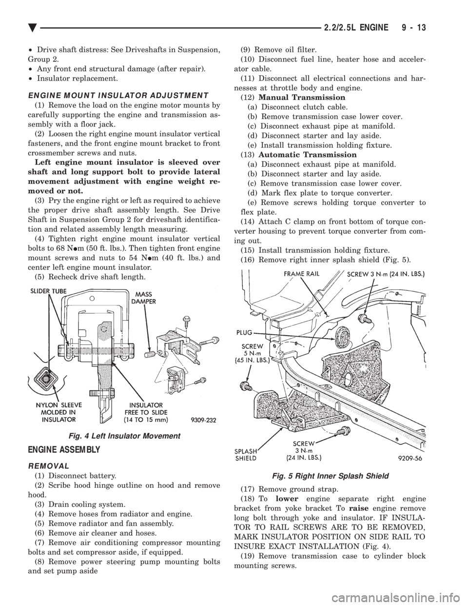
(16) Remove right inner splash shield (Fig. 5).
(17) Remove ground strap.
(18) To lowerengine separate right engine
bracket from yoke bracket To raiseengine remove
long bolt through yoke and insulator. IF INSULA-
TOR TO RAIL SCREWS ARE TO BE REMOVED,
MARK INSULATOR POSITION ON SIDE RAIL TO
INSURE EXACT INSTALLATION (Fig. 4). (19) Remove transmission case to cylinder block
mounting screws.Fig. 5 Right Inner Splash Shield
Fig. 4 Left Insulator Movement
Ä 2.2/2.5L ENGINE 9 - 13
Page 1580 of 2438
CAUTION: Make sure clutch cable has been discon-
nected. (20) Remove front engine mount screw and nut.
(21) Remove manual transmission damper.
(22) Remove left insulator through bolt from inside
wheelhouse or insulator bracket to transmission
screws. (23) Remove engine from vehicle.
INSTALLATION
(1) Install hoist to the engine and lower engine
into the engine compartment. SEE: ENGINE MOUNT RUBBER INSULATORS,
THIS GROUP. (2) Align engine mounts and install but do not
tighten until all mounting bolts have been installed.
(3) Install transmission case to cylinder block
mounting screws. Tighten to 95 N Im (70 ft. lbs.)
torque. (4) Remove engine hoist and transmission holding
fixture. (5) Install ground strap.
(6) Install right inner splash shield.
(7) Connect starter. See Electrical Group 8 for in-
stallation. (8) Connect exhaust system. See Exhaust Systems
Group 11 for installation. (9) Manual Transmission: Install transmission
case lower cover. Automatic Transmission: Remove C clamp from
torque converter housing. Align flexplate to torque
converter and install mounting screws. Tighten to 75
N Im (55 ft. lbs.) torque.
(10) Manual Transmission: Connect clutch cable.
See Clutch Group 6. (11) Install power steering pump. Refer to Cooling
System Group 7, Accessory Drive Section for belt
tension adjustment. (12) Connect fuel line, heater hose, and accelerator
cable. (13) Connect all electrical connections and har-
nesses at throttle body and engine. (14) Install oil filter. Fill engine crankcase with
proper oil to correct level. (15) Install air conditioning compressor (if
equipped). See Heater and Air Conditioning, Group
24 for installation. (16) Install air cleaner and hoses.
(17) Install radiator and shroud assembly . Install
radiator hoses. Fill cooling system. See Cooling Sys-
tem Group 7 for filling procedure. (18) Install hood.
(19) Connect battery.
(20) Start engine and run until operating temper-
ature is reached. (21) Adjust transmission linkage, if necessary.
SOLID MOUNT COMPRESSOR BRACKET SERVICE
When service procedures require solid mount
bracket removal and installation for example: cylin-
der head removal, etc., it is important that bracket
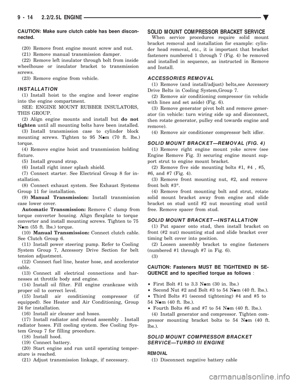
fasteners numbered 1 through 7 (Fig. 4) be removed
and installed in sequence, as instructed in Remove
and Install.
ACCESSORIES REMOVAL
(1) Remove (and install/adjust) belts,see Accessory
Drive Belts in Cooling System,Group 7. (2) Remove air conditioning compressor (in vehicle
with lines and set aside) (Fig. 6). (3) Remove generator pivot bolt and remove gener-
ator (in vehicle: turn wiring side up and disconnect,
then rotate generator, pulley end towards engine and
remove). (4) Remove air conditioner compressor belt idler.
SOLID MOUNT BRACKETÐREMOVAL (FIG. 4)
(1) Remove right engine mount yoke screw (see
Engine Remove Fig. 3) securing engine mount sup-
port strut to engine mount bracket. (2) Remove five side mounting bolts #1, #4 , #5,
#6, and #7 (Fig. 4). (3) Remove front mounting nut, #2, and remove
front bolt #3*. (4) Remove front mounting bolt and strut, rotate
solid mount bracket away from engine and slide
bracket on stud until #2 nut mounting stud until
free. Remove spacer from stud.
SOLID MOUNT BRACKETÐINSTALLATION
(1) Put spacer onto stud, then install bracket on
front (#2 nut) mounting stud and slide bracket over
timing belt cover into position. (2) Loosen assembly bracket to engine fasteners
(numbered #1 through #7 in Fig. 6). (3)
CAUTION: Fasteners MUST BE TIGHTENED IN SE-
QUENCE and to specified torque as follows :
² First Bolt #1 to 3.3 N Im (30 in. lbs.)
² Second Nut #2 and Bolt #3 to 54 N Im (40 ft. lbs.).
² Third Bolts #1 (second tightening) #4 and #5 to
54 N Im (40 ft. lbs.).
² Fourth Bolts #6 and #7 to 54 N Im (40 ft. lbs.).
(4) Install generator and compressor. Tighten com-
pressor mounting bracket bolts to 54 N Im (40 ft.
lbs.).
SOLID MOUNT COMPRESSOR BRACKET SERVICEÐTURBO III ENGINE
REMOVAL
(1) Disconnect negative battery cable
9 - 14 2.2/2.5L ENGINE Ä
Page 1582 of 2438
POWER STEERING/ACCESSORY DRIVE BELT TENSIONER BRACKET
REMOVAL
(1) Remove Accessory Drive Belt. Refer to Cooling
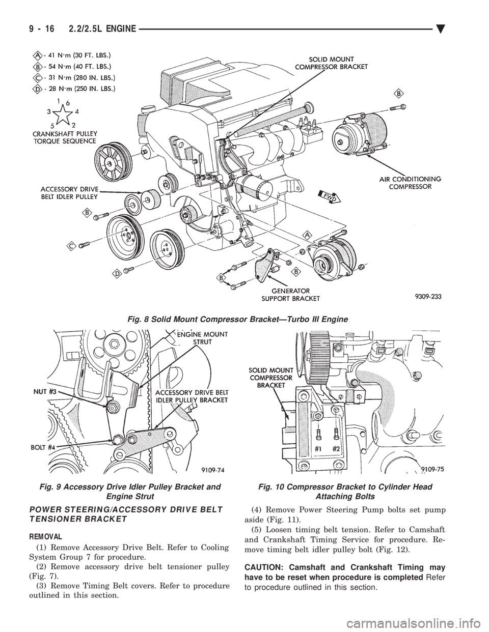
System Group 7 for procedure. (2) Remove accessory drive belt tensioner pulley
(Fig. 7). (3) Remove Timing Belt covers. Refer to procedure
outlined in this section. (4) Remove Power Steering Pump bolts set pump
aside (Fig. 11). (5) Loosen timing belt tension. Refer to Camshaft
and Crankshaft Timing Service for procedure. Re-
move timing belt idler pulley bolt (Fig. 12).
CAUTION: Camshaft and Crankshaft Timing may
have to be reset when procedure is completed Refer
to procedure outlined in this section.
Fig. 8 Solid Mount Compressor BracketÐTurbo III Engine
Fig. 9 Accessory Drive Idler Pulley Bracket and Engine StrutFig. 10 Compressor Bracket to Cylinder HeadAttaching Bolts
9 - 16 2.2/2.5L ENGINE Ä
Page 1583 of 2438
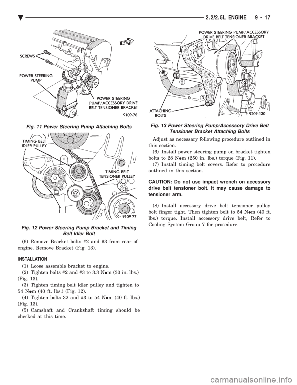
(6) Remove Bracket bolts #2 and #3 from rear of
engine. Remove Bracket (Fig. 13).
INSTALLATION (1) Loose assemble bracket to engine.
(2) Tighten bolts #2 and #3 to 3.3 N Im (30 in. lbs.)
(Fig. 13). (3) Tighten timing belt idler pulley and tighten to
54 N Im (40 ft. lbs.) (Fig. 12).
(4) Tighten bolts 32 and #3 to 54 N Im (40 ft. lbs.)
(Fig. 13). (5) Camshaft and Crankshaft timing should be
checked at this time. Adjust as necessary following procedure outlined in
this section. (6) Install power steering pump on bracket tighten
bolts to 28 N Im (250 in. lbs.) torque (Fig. 11).
(7) Install timing belt covers. Refer to procedure
outlined in this section.
CAUTION: Do not use impact wrench on accessory
drive belt tensioner bolt. It may cause damage to
tensioner arm.
(8) Install accessory drive belt tensioner pulley
bolt finger tight. Then tighten bolt to 54 N Im (40 ft.
lbs.) torque. Install accessory drive belt, Refer to
Cooling System Group 7 for procedure.
Fig. 11 Power Steering Pump Attaching Bolts
Fig. 12 Power Steering Pump Bracket and Timing Belt Idler Bolt
Fig. 13 Power Steering Pump/Accessory Drive BeltTensioner Bracket Attaching Bolts
Ä 2.2/2.5L ENGINE 9 - 17
Page 1592 of 2438
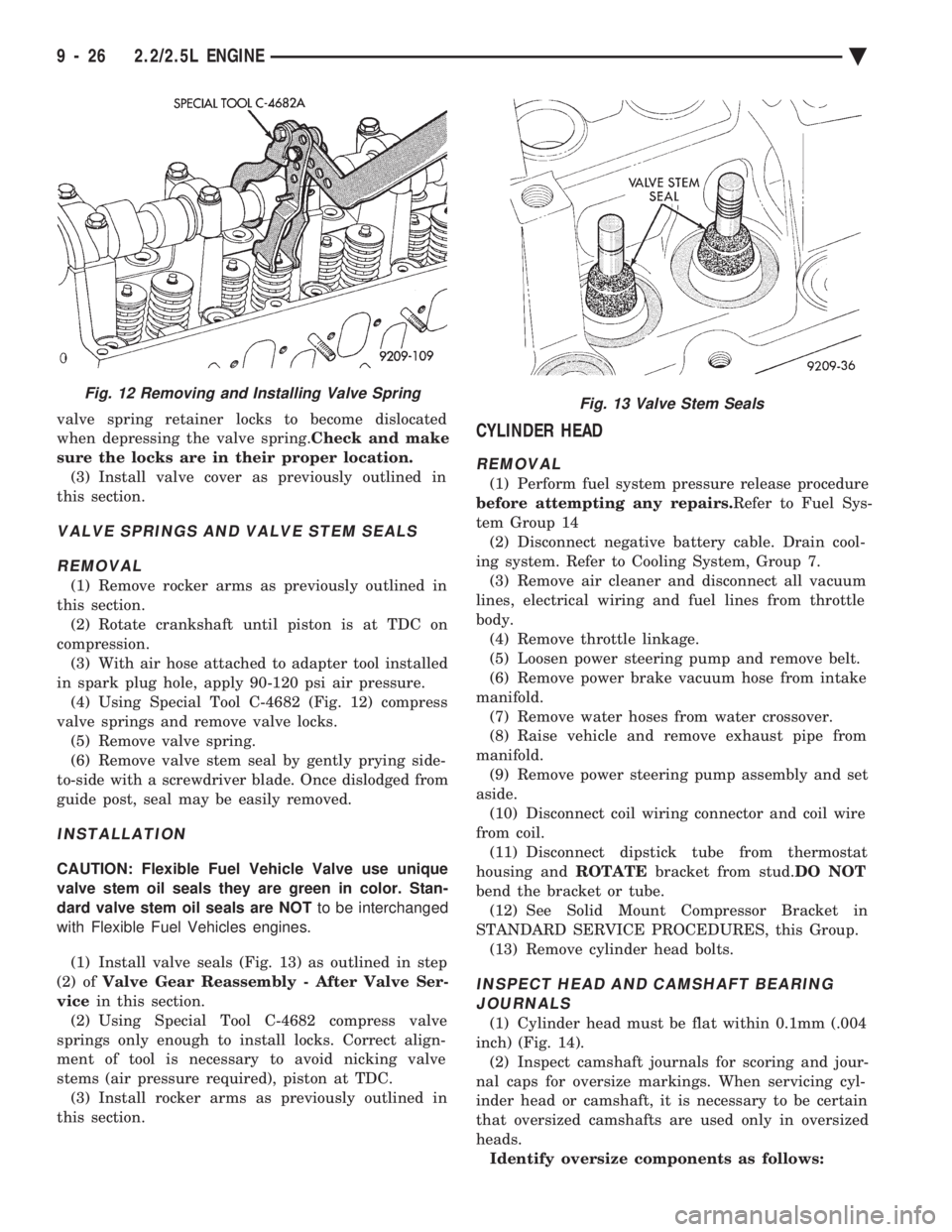
valve spring retainer locks to become dislocated
when depressing the valve spring. Check and make
sure the locks are in their proper location. (3) Install valve cover as previously outlined in
this section.
VALVE SPRINGS AND VALVE STEM SEALS
REMOVAL
(1) Remove rocker arms as previously outlined in
this section. (2) Rotate crankshaft until piston is at TDC on
compression. (3) With air hose attached to adapter tool installed
in spark plug hole, apply 90-120 psi air pressure. (4) Using Special Tool C-4682 (Fig. 12) compress
valve springs and remove valve locks. (5) Remove valve spring.
(6) Remove valve stem seal by gently prying side-
to-side with a screwdriver blade. Once dislodged from
guide post, seal may be easily removed.
INSTALLATION
CAUTION: Flexible Fuel Vehicle Valve use unique
valve stem oil seals they are green in color. Stan-
dard valve stem oil seals are NOT to be interchanged
with Flexible Fuel Vehicles engines.
(1) Install valve seals (Fig. 13) as outlined in step
(2) of Valve Gear Reassembly - After Valve Ser-
vice in this section.
(2) Using Special Tool C-4682 compress valve
springs only enough to install locks. Correct align-
ment of tool is necessary to avoid nicking valve
stems (air pressure required), piston at TDC. (3) Install rocker arms as previously outlined in
this section.
CYLINDER HEAD
REMOVAL
(1) Perform fuel system pressure release procedure
before attempting any repairs. Refer to Fuel Sys-
tem Group 14 (2) Disconnect negative battery cable. Drain cool-
ing system. Refer to Cooling System, Group 7. (3) Remove air cleaner and disconnect all vacuum
lines, electrical wiring and fuel lines from throttle
body. (4) Remove throttle linkage.
(5) Loosen power steering pump and remove belt.
(6) Remove power brake vacuum hose from intake
manifold. (7) Remove water hoses from water crossover.
(8) Raise vehicle and remove exhaust pipe from
manifold. (9) Remove power steering pump assembly and set
aside. (10) Disconnect coil wiring connector and coil wire
from coil. (11) Disconnect dipstick tube from thermostat
housing and ROTATEbracket from stud. DO NOT
bend the bracket or tube. (12) See Solid Mount Compressor Bracket in
STANDARD SERVICE PROCEDURES, this Group. (13) Remove cylinder head bolts.
INSPECT HEAD AND CAMSHAFT BEARINGJOURNALS
(1) Cylinder head must be flat within 0.1mm (.004
inch) (Fig. 14). (2) Inspect camshaft journals for scoring and jour-
nal caps for oversize markings. When servicing cyl-
inder head or camshaft, it is necessary to be certain
that oversized camshafts are used only in oversized
heads. Identify oversize components as follows:
Fig. 12 Removing and Installing Valve SpringFig. 13 Valve Stem Seals
9 - 26 2.2/2.5L ENGINE Ä