ECO mode CHEVROLET DYNASTY 1993 Owner's Manual
[x] Cancel search | Manufacturer: CHEVROLET, Model Year: 1993, Model line: DYNASTY, Model: CHEVROLET DYNASTY 1993Pages: 2438, PDF Size: 74.98 MB
Page 352 of 2438
SERVICE PROCEDURES INDEX
page page
Automatic Transmission Oil Coolers .......... 23
Coolant ................................ 14
Coolant Recovery System (CRS) ............. 17
Cooling System Drain, Clean, Flush and Refill . . 15
Electric Fan Motor ........................ 22
Engine Thermostats ....................... 13
Fan Shroud ............................. 23 Fans
.................................. 21
Radiator Hoses .......................... 21
Radiator Pressure Cap .................... 18
Radiators ............................... 18
Testing System for Leaks .................. 17
Water Pumps ........................... 10
WATER PUMPS
A quick test to tell whether or not the pump is
working is to see if the heater warms properly. A
defective pump will not be able to circulate heated
coolant through the long heater hose. The water pump on all models can be replaced
without discharging the air conditioning system.
WATER PUMPÐ2.2/2.5L ENGINE
The 2.2/2.5L engine water pump has a diecast alu-
minum body and housing with a stamped steel impel-
ler. The 2.2/2.5L pump uses an O-ring gasket between
body and housing. The assembly bolts directly to the
block. Cylinder block to water pump sealing is provided
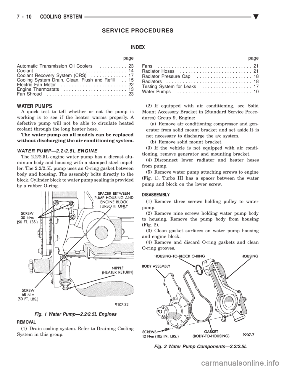
by a rubber O-ring.
REMOVAL (1) Drain cooling system. Refer to Draining Cooling
System in this group. (2) If equipped with air conditioning, see Solid
Mount Accessory Bracket in (Standard Service Proce-
dures) Group 9, Engine: (a) Remove air conditioning compressor and gen-
erator from solid mount bracket and set aside.It is
not necessary to discharge the a/c system. (b) Remove solid mount bracket.
(3) If the vehicle is not equipped with air condi-
tioning, remove generator and mounting bracket. (4) Disconnect lower radiator and heater hoses
from pump. (5) Remove water pump attaching screws to engine
(Fig. 1). Turbo III has a spacer between the water
pump and block on the lower screw.
DISASSEMBLY (1) Remove three screws holding pulley to water
pump. (2) Remove nine screws holding water pump body
to housing. Remove the pump body from housing
(Fig. 2). (3) Clean gasket surfaces on water pump housing
and engine block. (4) Remove and discard O-ring gaskets and clean
O-ring grooves.
Fig. 2 Water Pump ComponentsÐ2.2/2.5L
Fig. 1 Water PumpÐ2.2/2.5L Engines
7 - 10 COOLING SYSTEM Ä
Page 359 of 2438
TESTING SYSTEM FOR LEAKS
With engine not running, wipe the radiator filler
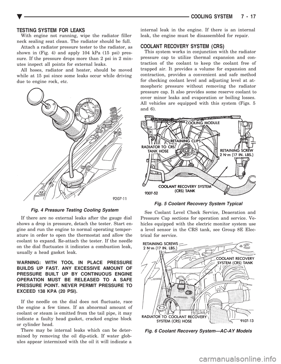
neck sealing seat clean. The radiator should be full. Attach a radiator pressure tester to the radiator, as
shown in (Fig. 4) and apply 104 kPa (15 psi) pres-
sure. If the pressure drops more than 2 psi in 2 min-
utes inspect all points for external leaks. All hoses, radiator and heater, should be moved
while at 15 psi since some leaks occur while driving
due to engine rock, etc.
If there are no external leaks after the gauge dial
shows a drop in pressure, detach the tester. Start en-
gine and run the engine to normal operating temper-
ature in order to open the thermostat and allow the
coolant to expand. Re-attach the tester. If the needle
on the dial fluctuates it indicates a combustion leak,
usually a head gasket leak.
WARNING: WITH TOOL IN PLACE PRESSURE
BUILDS UP FAST. ANY EXCESSIVE AMOUNT OF
PRESSURE BUILT UP BY CONTINUOUS ENGINE
OPERATION MUST BE RELEASED TO A SAFE
PRESSURE POINT. NEVER PERMIT PRESSURE TO
EXCEED 138 KPA (20 PSI).
If the needle on the dial does not fluctuate, race
the engine a few times. If an abnormal amount of
coolant or steam is emitted from the tail pipe, it may
indicate a faulty head gasket, cracked engine block
or cylinder head. There may be internal leaks which can be deter-
mined by removing the oil dip-stick. If water glob-
ules appear intermixed with the oil it will indicate a internal leak in the engine. If there is an internal
leak, the engine must be disassembled for repair.
COOLANT RECOVERY SYSTEM (CRS)
This system works in conjunction with the radiator
pressure cap to utilize thermal expansion and con-
traction of the coolant to keep the coolant free of
trapped air. It provides a volume for expansion and
contraction, provides a convenient and safe method
for checking coolant level and adjusting level at at-
mospheric pressure without removing the radiator
pressure cap. It also provides some reserve coolant to
cover minor leaks and evaporation or boiling losses.
All vehicles are equipped with this system (Figs. 5
and 6).
See Coolant Level Check Service, Deaeration and
Pressure Cap sections for operation and service. Ve-
hicles equipped with the electric monitor system use
a level sensor in the CRS tank, see Group 8E Elec-
trical for service.
Fig. 4 Pressure Testing Cooling System
Fig. 5 Coolant Recovery System Typical
Fig. 6 Coolant Recovery SystemÐAC-AY Models
Ä COOLING SYSTEM 7 - 17
Page 363 of 2438
RADIATOR HOSES
The hoses are removed using Constant Tension
Clamp pliers to compress hose clamp. A hardened, cracked, swollen or restricted hose
should be replaced. Do not damage radiator inlet and
outlet when loosening hoses. Radiator hoses should be routed without any kinks
and indexed as designed. The use of molded hoses is
recommended. Spring type hose clamps are used in all applica-
tions. If replacement is necessary replace with the
original style spring type clamp.
FANS
All models use electric motor driven cooling system
fans. The fan modules include a motor support which
may (depending on model) include a shroud. The
module is fastened to the radiator by screws with
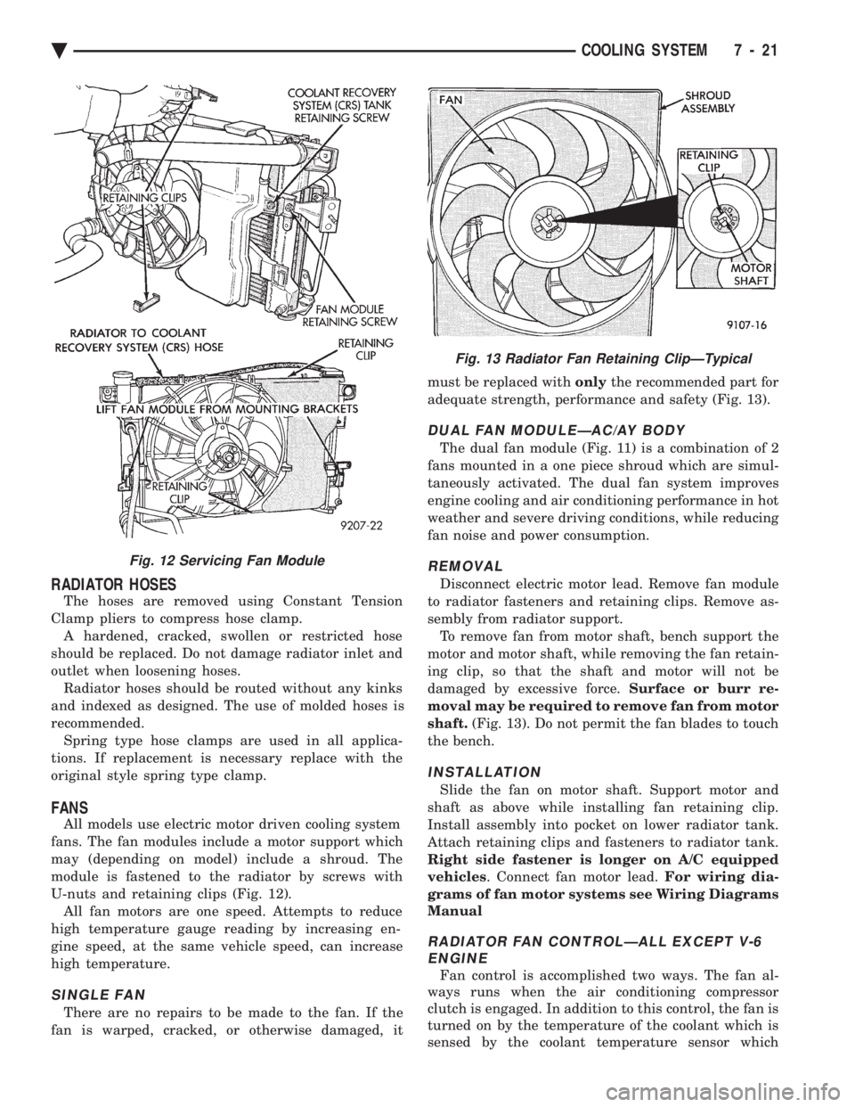
U-nuts and retaining clips (Fig. 12). All fan motors are one speed. Attempts to reduce
high temperature gauge reading by increasing en-
gine speed, at the same vehicle speed, can increase
high temperature.
SINGLE FAN
There are no repairs to be made to the fan. If the
fan is warped, cracked, or otherwise damaged, it must be replaced with
onlythe recommended part for
adequate strength, performance and safety (Fig. 13).
DUAL FAN MODULEÐAC/AY BODY
The dual fan module (Fig. 11) is a combination of 2
fans mounted in a one piece shroud which are simul-
taneously activated. The dual fan system improves
engine cooling and air conditioning performance in hot
weather and severe driving conditions, while reducing
fan noise and power consumption.
REMOVAL
Disconnect electric motor lead. Remove fan module
to radiator fasteners and retaining clips. Remove as-
sembly from radiator support. To remove fan from motor shaft, bench support the
motor and motor shaft, while removing the fan retain-
ing clip, so that the shaft and motor will not be
damaged by excessive force. Surface or burr re-
moval may be required to remove fan from motor
shaft. (Fig. 13). Do not permit the fan blades to touch
the bench.
INSTALLATION
Slide the fan on motor shaft. Support motor and
shaft as above while installing fan retaining clip.
Install assembly into pocket on lower radiator tank.
Attach retaining clips and fasteners to radiator tank.
Right side fastener is longer on A/C equipped
vehicles . Connect fan motor lead. For wiring dia-
grams of fan motor systems see Wiring Diagrams
Manual
RADIATOR FAN CONTROLÐALL EXCEPT V-6 ENGINE
Fan control is accomplished two ways. The fan al-
ways runs when the air conditioning compressor
clutch is engaged. In addition to this control, the fan is
turned on by the temperature of the coolant which is
sensed by the coolant temperature sensor which
Fig. 12 Servicing Fan Module
Fig. 13 Radiator Fan Retaining ClipÐTypical
Ä COOLING SYSTEM 7 - 21
Page 370 of 2438
ENGINE BLOCK HEATER
DESCRIPTION AND OPERATION
On all models an engine block heater is available as
an optional accessory. The heater, operated by ordinary
house current (110 Volt A.C.) through a power cord and
connector behind the radiator grille, provides easier
engine starting and faster warm-up when vehicle is
operated in areas having extremely low temperatures.
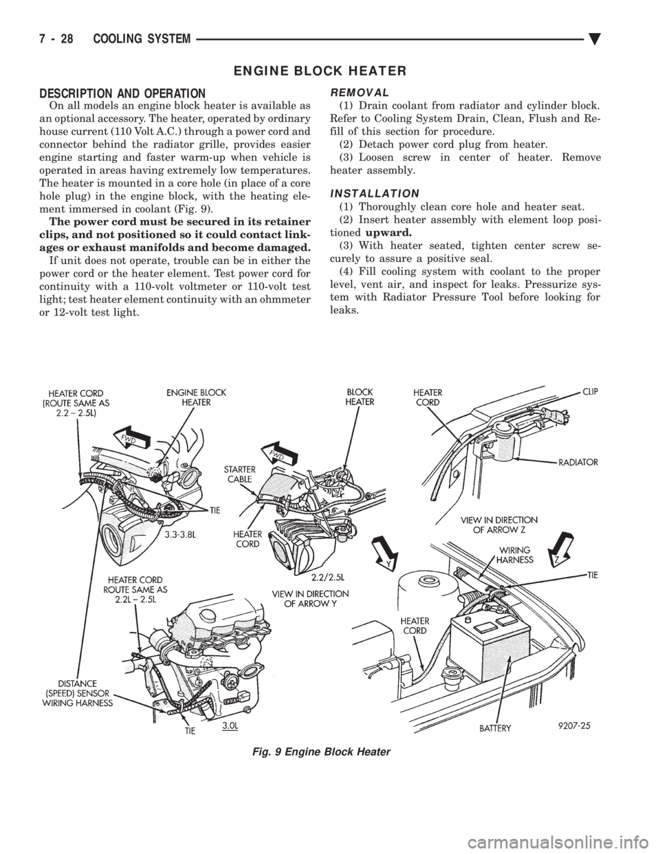
The heater is mounted in a core hole (in place of a core
hole plug) in the engine block, with the heating ele-
ment immersed in coolant (Fig. 9). The power cord must be secured in its retainer
clips, and not positioned so it could contact link-
ages or exhaust manifolds and become damaged. If unit does not operate, trouble can be in either the
power cord or the heater element. Test power cord for
continuity with a 110-volt voltmeter or 110-volt test
light; test heater element continuity with an ohmmeter
or 12-volt test light.
REMOVAL
(1) Drain coolant from radiator and cylinder block.
Refer to Cooling System Drain, Clean, Flush and Re-
fill of this section for procedure. (2) Detach power cord plug from heater.
(3) Loosen screw in center of heater. Remove
heater assembly.
INSTALLATION
(1) Thoroughly clean core hole and heater seat.
(2) Insert heater assembly with element loop posi-
tioned upward.
(3) With heater seated, tighten center screw se-
curely to assure a positive seal. (4) Fill cooling system with coolant to the proper
level, vent air, and inspect for leaks. Pressurize sys-
tem with Radiator Pressure Tool before looking for
leaks.
Fig. 9 Engine Block Heater
7 - 28 COOLING SYSTEM Ä
Page 381 of 2438
IGNITION OFF DRAW (IOD)
GENERAL INFORMATION
A normal electrical system will draw from 5 to 30
milliamperes from the battery. This is with the ignition
in the OFF position, and all non-ignition controlled cir-
cuits in proper working order. The amount of IOD will
depend on body model and electrical components. A ve-
hicle that has not been operated for an extended period
of approximately 20 days may discharge the battery to
an inadequate level. In this case, the Main Fusible Link
Connector should be disconnected. The Main Fusible
Link connector is located rearward of the battery on the
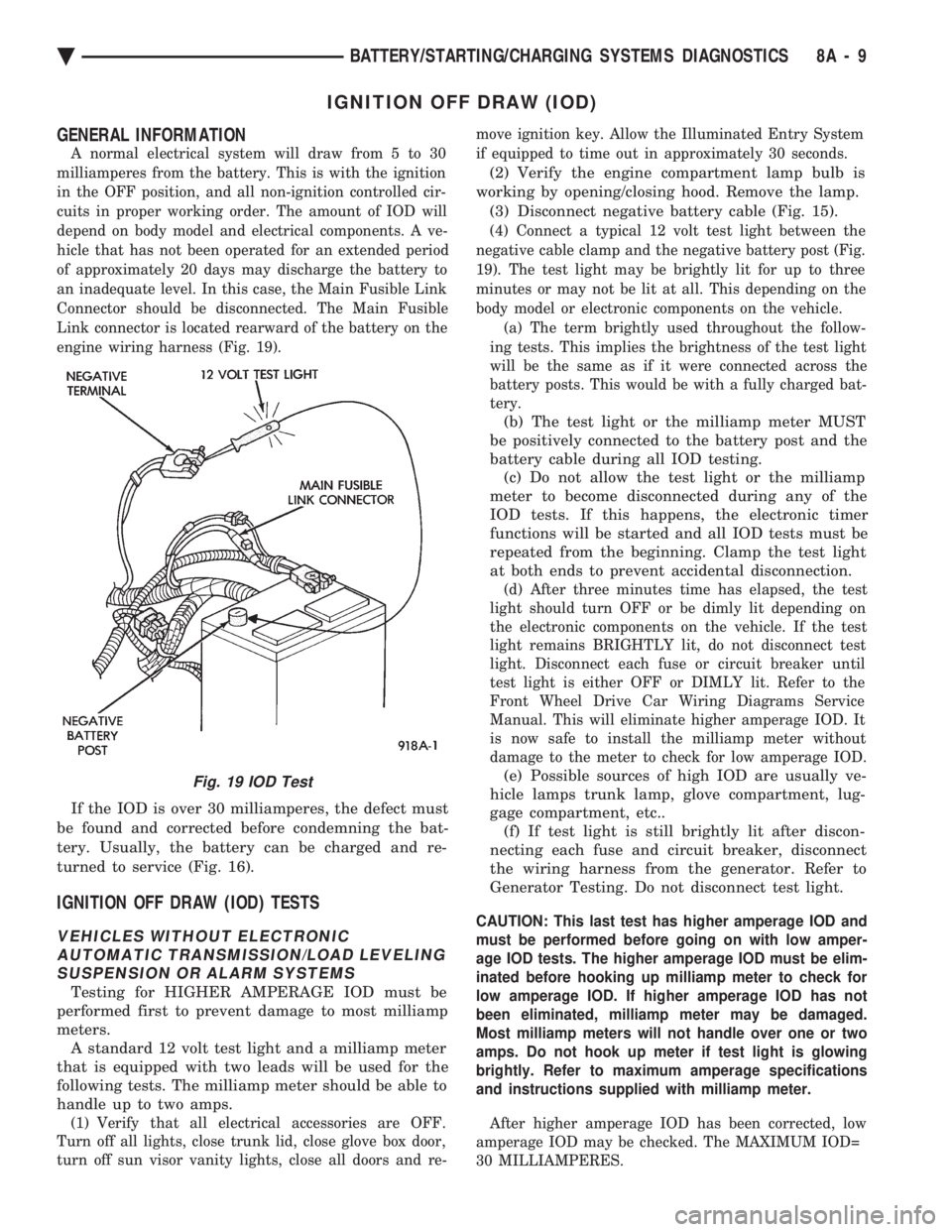
engine wiring harness (Fig. 19).
If the IOD is over 30 milliamperes, the defect must
be found and corrected before condemning the bat-
tery. Usually, the battery can be charged and re-
turned to service (Fig. 16).
IGNITION OFF DRAW (IOD) TESTS
VEHICLES WITHOUT ELECTRONIC AUTOMATIC TRANSMISSION/LOAD LEVELINGSUSPENSION OR ALARM SYSTEMS
Testing for HIGHER AMPERAGE IOD must be
performed first to prevent damage to most milliamp
meters. A standard 12 volt test light and a milliamp meter
that is equipped with two leads will be used for the
following tests. The milliamp meter should be able to
handle up to two amps.
(1) Verify that all electrical accessories are OFF.
Turn off all lights, close trunk lid, close glove box door,
turn off sun visor vanity lights, close all doors and re- move ignition key. Allow the Illuminated Entry System
if equipped to time out in approximately 30 seconds.
(2) Verify the engine compartment lamp bulb is
working by opening/closing hood. Remove the lamp. (3) Disconnect negative battery cable (Fig. 15).
(4) Connect a typical 12 volt test light between the
negative cable clamp and the negative battery post (Fig.
19). The test light may be brightly lit for up to three
minutes or may not be lit at all. This depending on the
body model or electronic components on the vehicle. (a) The term brightly used throughout the follow-
ing tests. This implies the brightness of the test light
will be the same as if it were connected across the
battery posts. This would be with a fully charged bat-
tery.
(b) The test light or the milliamp meter MUST
be positively connected to the battery post and the
battery cable during all IOD testing. (c) Do not allow the test light or the milliamp
meter to become disconnected during any of the
IOD tests. If this happens, the electronic timer
functions will be started and all IOD tests must be
repeated from the beginning. Clamp the test light
at both ends to prevent accidental disconnection.
(d) After three minutes time has elapsed, the test
light should turn OFF or be dimly lit depending on
the electronic components on the vehicle. If the test
light remains BRIGHTLY lit, do not disconnect test
light. Disconnect each fuse or circuit breaker until
test light is either OFF or DIMLY lit. Refer to the
Front Wheel Drive Car Wiring Diagrams Service
Manual. This will eliminate higher amperage IOD. It
is now safe to install the milliamp meter without
damage to the meter to check for low amperage IOD.
(e) Possible sources of high IOD are usually ve-
hicle lamps trunk lamp, glove compartment, lug-
gage compartment, etc.. (f) If test light is still brightly lit after discon-
necting each fuse and circuit breaker, disconnect
the wiring harness from the generator. Refer to
Generator Testing. Do not disconnect test light.
CAUTION: This last test has higher amperage IOD and
must be performed before going on with low amper-
age IOD tests. The higher amperage IOD must be elim-
inated before hooking up milliamp meter to check for
low amperage IOD. If higher amperage IOD has not
been eliminated, milliamp meter may be damaged.
Most milliamp meters will not handle over one or two
amps. Do not hook up meter if test light is glowing
brightly. Refer to maximum amperage specifications
and instructions supplied with milliamp meter.
After higher amperage IOD has been corrected, low
amperage IOD may be checked. The MAXIMUM IOD=
30 MILLIAMPERES.
Fig. 19 IOD Test
Ä BATTERY/STARTING/CHARGING SYSTEMS DIAGNOSTICS 8A - 9
Page 420 of 2438
VARIANCE SETTING PROCEDURE
There are two methods for setting variance while
in variance set mode. If the CAL symbol is on proce-
dure 2 must be used.
PROCEDURE 1
(1) Turn ignition switch to the on position.
(2) Press and hold the Comp/Temp button till the
display is turned OFF. (3) While continuing to hold Comp/Temp button
depress and hold US/Metric button until the VAR
symbol lights in approximately 5 seconds. (4) Release buttons.
(5) To determine the zone number which, corre-
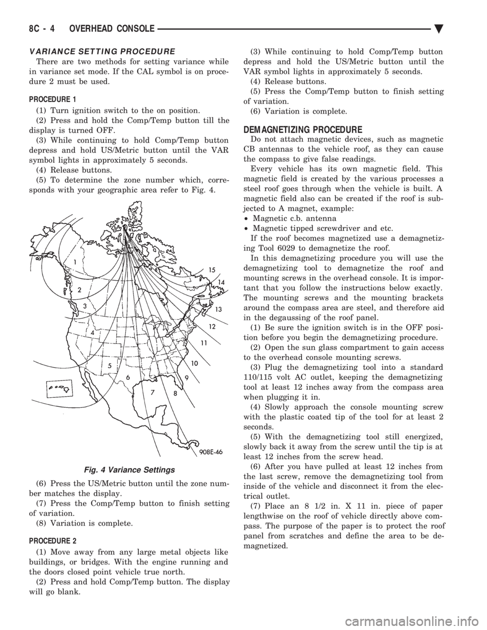
sponds with your geographic area refer to Fig. 4.
(6) Press the US/Metric button until the zone num-
ber matches the display. (7) Press the Comp/Temp button to finish setting
of variation. (8) Variation is complete.
PROCEDURE 2 (1) Move away from any large metal objects like
buildings, or bridges. With the engine running and
the doors closed point vehicle true north. (2) Press and hold Comp/Temp button. The display
will go blank. (3) While continuing to hold Comp/Temp button
depress and hold the US/Metric button until the
VAR symbol lights in approximately 5 seconds. (4) Release buttons.
(5) Press the Comp/Temp button to finish setting
of variation. (6) Variation is complete.
DEMAGNETIZING PROCEDURE
Do not attach magnetic devices, such as magnetic
CB antennas to the vehicle roof, as they can cause
the compass to give false readings. Every vehicle has its own magnetic field. This
magnetic field is created by the various processes a
steel roof goes through when the vehicle is built. A
magnetic field also can be created if the roof is sub-
jected to A magnet, example:
² Magnetic c.b. antenna
² Magnetic tipped screwdriver and etc.
If the roof becomes magnetized use a demagnetiz-
ing Tool 6029 to demagnetize the roof. In this demagnetizing procedure you will use the
demagnetizing tool to demagnetize the roof and
mounting screws in the overhead console. It is impor-
tant that you follow the instructions below exactly.
The mounting screws and the mounting brackets
around the compass area are steel, and therefore aid
in the degaussing of the roof panel. (1) Be sure the ignition switch is in the OFF posi-
tion before you begin the demagnetizing procedure. (2) Open the sun glass compartment to gain access
to the overhead console mounting screws. (3) Plug the demagnetizing tool into a standard
110/115 volt AC outlet, keeping the demagnetizing
tool at least 12 inches away from the compass area
when plugging it in. (4) Slowly approach the console mounting screw
with the plastic coated tip of the tool for at least 2
seconds. (5) With the demagnetizing tool still energized,
slowly back it away from the screw until the tip is at
least 12 inches from the screw head. (6) After you have pulled at least 12 inches from
the last screw, remove the demagnetizing tool from
inside of the vehicle and disconnect it from the elec-
trical outlet. (7) Place an 8 1/2 in. X 11 in. piece of paper
lengthwise on the roof of vehicle directly above com-
pass. The purpose of the paper is to protect the roof
panel from scratches and define the area to be de-
magnetized.
Fig. 4 Variance Settings
8C - 4 OVERHEAD CONSOLE Ä
Page 421 of 2438
(8) Plug in the demagnetizing tool, keeping it at
least 2 feet away from the compass unit. (9) Slowly approach the center of the roof panel at
the windshield with the demagnetizing tool plugged
in.
² Contact the roof panel with the tip of the tool.
² Using slow sweeping motions of 1/2 inch between
sweeps
² Move the tool approximately 4 inches either side of
the centerline, and at least 11 inches back from the
windshield. (10) With the demagnetizing tool still energized,
slowly back away from the roof panel until the tip is
at least two feet from the roof before unplugging the
tool. (11) Recalibrate compass.
COMPASS DIAGNOSTICS
To place the unit into the diagnostics mode, turn
the vehicle ignition off. Depress the Comp/Temp but-
ton while turning on the ignition/run switch. The
display will then show DO. There are three tests that
can be performed when in the diagnostics mode.
Press the U.S./Metric button to choose test desired
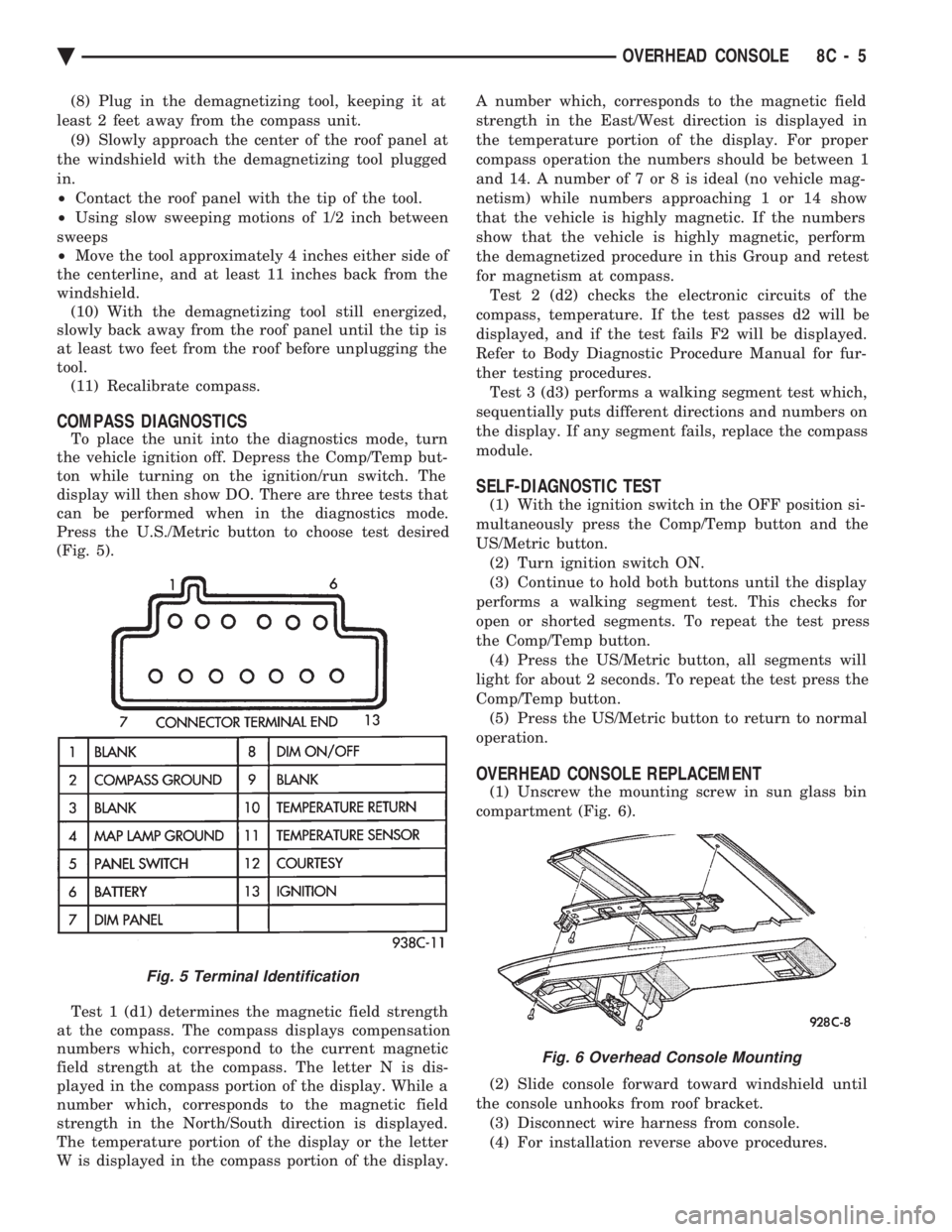
(Fig. 5).
Test 1 (d1) determines the magnetic field strength
at the compass. The compass displays compensation
numbers which, correspond to the current magnetic
field strength at the compass. The letter N is dis-
played in the compass portion of the display. While a
number which, corresponds to the magnetic field
strength in the North/South direction is displayed.
The temperature portion of the display or the letter
W is displayed in the compass portion of the display. A number which, corresponds to the magnetic field
strength in the East/West direction is displayed in
the temperature portion of the display. For proper
compass operation the numbers should be between 1
and 14. A number of 7 or 8 is ideal (no vehicle mag-
netism) while numbers approaching 1 or 14 show
that the vehicle is highly magnetic. If the numbers
show that the vehicle is highly magnetic, perform
the demagnetized procedure in this Group and retest
for magnetism at compass. Test 2 (d2) checks the electronic circuits of the
compass, temperature. If the test passes d2 will be
displayed, and if the test fails F2 will be displayed.
Refer to Body Diagnostic Procedure Manual for fur-
ther testing procedures. Test 3 (d3) performs a walking segment test which,
sequentially puts different directions and numbers on
the display. If any segment fails, replace the compass
module.
SELF-DIAGNOSTIC TEST
(1) With the ignition switch in the OFF position si-
multaneously press the Comp/Temp button and the
US/Metric button. (2) Turn ignition switch ON.
(3) Continue to hold both buttons until the display
performs a walking segment test. This checks for
open or shorted segments. To repeat the test press
the Comp/Temp button. (4) Press the US/Metric button, all segments will
light for about 2 seconds. To repeat the test press the
Comp/Temp button. (5) Press the US/Metric button to return to normal
operation.
OVERHEAD CONSOLE REPLACEMENT
(1) Unscrew the mounting screw in sun glass bin
compartment (Fig. 6).
(2) Slide console forward toward windshield until
the console unhooks from roof bracket. (3) Disconnect wire harness from console.
(4) For installation reverse above procedures.
Fig. 5 Terminal Identification
Fig. 6 Overhead Console Mounting
Ä OVERHEAD CONSOLE 8C - 5
Page 423 of 2438
² To set DAY of WEEK, press TIME button. An ar-
row will appear on the display and point to the Day.
Press and hold the SET button to move the day for-
ward or INFO button to move it backward.
² To set DAY of MONTH, press TIME button. The
arrow will point to Date. Press and hold the SET
button to advance the date or INFO button to move
it backwards.
² To set MONTH of YEAR, press TIME button. The
arrow will point to the Month. Press and hold the
SET button to advance the Month forward or INFO
button to move backward. TEMP button, pressing the Temp button will dis-
play:
² The temperature outside the vehicle
² Vehicle direction define by an eight point compass
If Compass has lost calibration or not receiving
good information from the engine compartment node,
an asterisk (*) will flash on the display and the word
calibrate will appear. Refer to Compass Calibration. FUEL BUTTON, WILL DISPLAY:
² Pressing FUEL button the first time will show, the
estimated number of miles that can be driven with
the remaining fuel. The destination to empty indica-
tion will vary every few seconds as the amount of
fuel and fuel efficiency is calculated. This function
can not be reset.
² Pressing the FUEL button second time; will dis-
play the fuel consumed.
²
Pressing the FUEL button third time; will display
the average fuel economy in miles per gallon since last
reset. The display will be updated every 16 seconds.
² Pressing the FUEL button forth time, the current
fuel economy will be displayed. The current fuel
economy will be up updated every two seconds.
² To reset Fuel consumed, press SET button until
the fuel consumed message is displayed and then
within five seconds press SET button.
² To reset AVERAGE FUEL ECONOMY, press the
FUEL button until average fuel economy is displayed
and within five seconds press SET button. TRIP RESET, press FUEL button and wait four
seconds press the SET button twice. This clears all
trip information and the message Trip Reset will be
displayed. This will occur only if a reset function is
currently being displayed. The reset functions:
² Fuel consumed
² Average fuel economy message
INFO button, will active a MONITORED SYS-
TEMS OK message on display if all monitored sys-
tems are operating properly. If a problem is detected,
the appropriate message will be displayed. SET button, will clear the various functions after
they have been displayed. It is used to enter the
clock set or compass variance modes. This button is
also used to reset certain trip computer functions and
the maintenance reminder message.
The EVIC display may be turned off by pressing the
TIME and SET buttons at the same time. Pressing the
buttons a second time will restore the display.
EVIC INFORMATION SOURCES
The EVIC monitors information provided by the
body controller, engine compartment node and pow-
ertrain control module. Refer to Body Diagnostic Test
Procedure Manual for test procedures. The Body Controller is a micro-controller unit
which, informs the EVIC overhead console via the
CCD bus of:
² Time of day
² Day of week
² Day of month
² Month of year
² Fuel range
² Fuel consumed
² Fuel efficiency
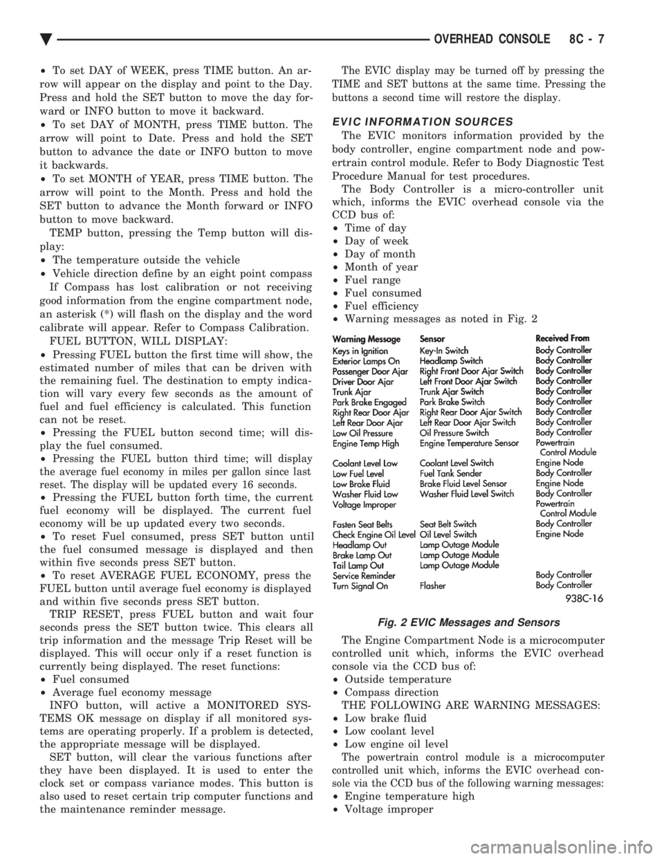
² Warning messages as noted in Fig. 2
The Engine Compartment Node is a microcomputer
controlled unit which, informs the EVIC overhead
console via the CCD bus of:
² Outside temperature
² Compass direction
THE FOLLOWING ARE WARNING MESSAGES:
² Low brake fluid
² Low coolant level
² Low engine oil level
The powertrain control module is a microcomputer
controlled unit which, informs the EVIC overhead con-
sole via the CCD bus of the following warning messages:
² Engine temperature high
² Voltage improper
Fig. 2 EVIC Messages and Sensors
Ä OVERHEAD CONSOLE 8C - 7
Page 424 of 2438
VISUAL MESSAGES
Following are the visual messages and the condi-
tions under which, the messages will be given:
² Keys in ignition
² Exterior lamps on
These messages will appear if the conditions are
present and the driver's door is open while the igni-
tion switch is in the OFF, LOCK, or ACC positions.
A tone will sound until the condition is corrected or
the door is closed.
² Passenger door ajar
² Driver door ajar
² Trunk ajar
² Park brake engaged
² Right rear door ajar
² Left rear door ajar
These messages will appear if a condition is de-
tected after the vehicle is in motion. When the con-
dition is corrected, a short tone will sound to
acknowledge the action. LOW OIL PRESSURE
If this message is displayed while the vehicle is at
cruising speeds, immediate attention is required. If
this message appears at idle speed, increase the idle
speed and the message should go off. If the message
remains on, immediate attention is required. ENGINE TEMP CRITICAL
This message appears when a sensor has determined
that the engine coolant is overheating. If this message
comes on and stays on, immediate action is required.
COOLANT LEVEL LOW
LOW FUEL LEVEL
LOW BRAKE FLUID
WASHER FLUID LOW
These messages will appear if a continuous warn-
ing condition is detected while the engine is running.
Inspection is required. To clear this message from
the display, after the condition is corrected, the igni-
tion switch must be turned OFF. CHECK TRANS
This message will appear if a continuous warning
condition is detected while the engine is running. Im-
mediate attention is recommended. To clear this mes-
sage from the display, after the condition has been
corrected, the ignition switch must be turned OFF. VOLTAGE IMPROPER
This message will appear if a continuous warning
condition is detected. Immediate attention is re-
quired. To clear this message from the display, after
the condition has been corrected, the ignition switch
must be turned OFF. TURN SIGNAL ON
This message will appear if the turn signal is left
on while vehicle speed is over 15 mph and the vehi-
cle has traveled over one-half mile. FASTEN SEAT BELTS An intermittent chime tone will sound for several
seconds if the seat belt is not fastened. CHK ENGINE OIL LEVEL
If this message is delivered, a check of the engine
oil dipstick is suggested. To clear this message, after
the condition is corrected, the ignition switch must
be turned OFF. HEADLAMP OUT
BRAKE LAMP OUT
TAIL LAMP OUT
These conditions are monitored only when the lamps
are on. The message will remain, even after the lamp is
replaced, until the lamp is turned on and operates.
SERVICE REMINDER
The maintenance reminder statement is programmed
to provide general information only. Refer to Group 0,
Lubrication & Maintenance for specific vehicle require-
ments.
The service reminder message is displayed at 7,500
miles or 12 months intervals, which ever comes first. MONITORED SYSTEMS OK
If there is no warning condition to report, the mes-
sage Monitored Systems OK is displayed (Fig. 2).
AUTOMATIC CALIBRATION SET PROCEDURE
The engine compartment node will continuously
and automatically recalibrate the compass under nor-
mal driving conditions. As long as the vehicle is
turning, the engine compartment node will record
new compass data. This new data will be used to
recalibrate the compass at a rate of at least once per
full (360 degree) turn of the vehicle. Automatic cali-
bration does not require operator interface.
MANUAL CALIBRATION SET PROCEDURE
Manual compass calibration has been replaced by
automatic calibration set procedure. The manual cal-
ibration set procedure is available, but no longer
serves any useful purpose.
EVIC SELF CHECK DIAGNOSTICS
Ignition switch ON, the EVIC not displaying any
message, may imply a system failure and not an
EVIC failure. Turn the ignition OFF, close all vehi-
cle doors and wait at least 60 seconds before begin-
ning test. Turn ignition switch to the ON position.
Pressing the TEMP, FUEL and INFO buttons at the
same time shall provide the visual message MOD-
ULE SELF CHECK for two seconds. Following at
two second interval there will be messages:
² E2-0 SELF CHECK
² E3-0 SELF CHECK
² END OF SELF CHECK
Showing the microcomputer is working properly.
When the self check mode and message shows:
² E2-1
² E3-2
This would show a fault exists in the EVIC's micro-
computer and the EVIC should be replaced (Fig. 3).
8C - 8 OVERHEAD CONSOLE Ä
Page 430 of 2438
dition exists. These messages are displayed on the
center of the instrument panel.For complete EVIC operating instructions, refer to
the Owners Manual provided with the vehicle.
EVIC BUTTON FUNCTIONS
TIME button will display:
² Time of day
² Day of week
² Day of month
² Month of year
² To set HOURS, press TIME button and within four
seconds press the SET button. An arrow will appear
on the display and point to the hours. Press and hold
the SET button to advance the hours or INFO button
to set back the hours.
² To set MINUTES, press TIME button. The arrow
will point to the minutes. Press and hold the SET
button to advance the minutes or INFO button to set
back the minutes.
² To set DAY of WEEK, press TIME button. An ar-
row will appear on the display and point to the Day.
Press and hold the SET button to move the day for-
ward or INFO button to move it backward.
² To set DAY of MONTH, press TIME button. The
arrow will point to Date. Press and hold the SET
button to advance the date or INFO button to move
it backwards.
² To set MONTH of YEAR, press TIME button. The
arrow will point to the Month. Press and hold the
SET button to advance the Month forward or INFO
button to move backward. TEMP button, pressing the Temp button will dis-
play:
² The temperature outside the vehicle
² Vehicle direction define by an eight point compass
If Compass has lost calibration or not receiving
good information from the engine compartment node,
an asterisk (*) will flash on the display and the word
calibrate will appear. Refer to Compass Calibration. FUEL BUTTON, WILL DISPLAY:
² Pressing FUEL button the first time will show, the
estimated number of miles that can be driven with
the remaining fuel. The destination to empty indica-
tion will vary every few seconds as the amount of
fuel and fuel efficiency is calculated. This function
can not be reset.
² Pressing the FUEL button second time; will dis-
play the fuel consumed.
² Pressing the FUEL button third time; will display
the average fuel economy in miles per gallon since
last reset. The display will be updated every 16 sec-
onds.
² Pressing the FUEL button forth time, the current
fuel economy will be displayed. The current fuel
economy will be up updated every two seconds. ²
To reset Fuel consumed, press SET button until
the fuel consumed message is displayed and then
within five seconds press SET button.
² To reset AVERAGE FUEL ECONOMY, press the
FUEL button until average fuel economy is displayed
and within five seconds press SET button. TRIP RESET, press FUEL button and wait four
seconds press the SET button twice. This clears all
trip information and the message Trip Reset will be
displayed. This will occur only if a reset function is
currently being displayed. The reset functions:
² Fuel consumed
² Average fuel economy message
INFO button, will active a MONITORED SYS-
TEMS OK message on display if all monitored sys-
tems are operating properly. If a problem is detected,
the appropriate message will be displayed. SET button, will clear the various functions after
they have been displayed. It is used to enter the
clock set or compass variance modes. This button is
also used to reset certain trip computer functions and
the maintenance reminder message. The EVIC display may be turned off by pressing
the TIME and SET buttons at the same time. Press-
ing the buttons a second time will restore the dis-
play.
EVIC INFORMATION SOURCES
The EVIC monitors information provided by the
body controller, engine compartment node and pow-
ertrain control module. Refer to Body Diagnostic Test
Procedure Manual for test procedures. The Body Controller is a micro-controller unit
which, informs the EVIC via the CCD bus of:
² Time of day
² Day of week
² Day of month
² Month of year
² Fuel range
² Fuel consumed
² Fuel efficiency
² Warning messages as noted in Fig. 3.
The Engine Compartment Node is a microcomputer
controlled unit which, informs the EVIC via the CCD
bus of:
² Outside temperature
² Compass direction
THE FOLLOWING ARE WARNING MESSAGES:
² Low brake fluid
² Low coolant level
² Low engine oil level
The powertrain control module is a microcomputer
controlled unit which, informs the EVIC via the CCD
bus of the following warning messages:
² Engine temperature high
² Voltage improper
8C - 14 OVERHEAD CONSOLE Ä