ECO mode CHEVROLET DYNASTY 1993 Owner's Guide
[x] Cancel search | Manufacturer: CHEVROLET, Model Year: 1993, Model line: DYNASTY, Model: CHEVROLET DYNASTY 1993Pages: 2438, PDF Size: 74.98 MB
Page 434 of 2438
(12) Recalibrate compass.
COMPASS DIAGNOSTICS
To place the unit into the diagnostics mode, turn
the vehicle ignition off. Depress the Comp/Temp but-
ton while turning on the ignition/run switch. The
display will then show DO. There are 3 tests that
can be performed when in the diagnostics mode.
Press the U.S./Metric button to choose test desired
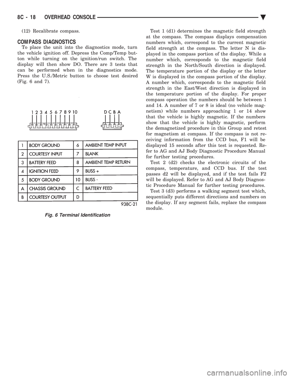
(Fig. 6 and 7). Test 1 (d1) determines the magnetic field strength
at the compass. The compass displays compensation
numbers which, correspond to the current magnetic
field strength at the compass. The letter N is dis-
played in the compass portion of the display. While a
number which, corresponds to the magnetic field
strength in the North/South direction is displayed.
The temperature portion of the display or the letter
W is displayed in the compass portion of the display.
A number which, corresponds to the magnetic field
strength in the East/West direction is displayed in
the temperature portion of the display. For proper
compass operation the numbers should be between 1
and 14. A number of 7 or 8 is ideal (no vehicle mag-
netism) while numbers approaching 1 or 14 show
that the vehicle is highly magnetic. If the numbers
show that the vehicle is highly magnetic, perform
the demagnetized procedure in this Group and retest
for magnetism at compass. If the compass is not re-
ceiving information from the CCD bus, F1 will be
displayed 15 seconds after this test is requested. Re-
fer to AG and AJ Body Diagnostic Procedure Manual
for further testing procedures. Test 2 (d2) checks the electronic circuits of the
compass, temperature, and CCD bus. If the test
passes d2 will be displayed, and if the test fails F2
will be displayed. Refer to AG and AJ Body Diagnos-
tic Procedure Manual for further testing procedures. Test 3 (d3) performs a walking segment test which,
sequentially puts different directions and numbers on
the display. If any segment fails, replace the compass
module.
Fig. 6 Terminal Identification
8C - 18 OVERHEAD CONSOLE Ä
Page 439 of 2438
(3) Plug the demagnetizing tool into a standard
110/115 volt AC outlet, keeping the demagnetizing
tool at least 12 inches away from the compass area
when plugging it in. (4) Slowly approach the console mounting screw
with the plastic coated tip of the tool for at least 2
seconds. (5) With the demagnetizing tool still energized,
slowly back it away from the screw until the tip is at
least 12 inches from the screw head. (6) After you have pulled at least 12 inches from
the last screw, remove the demagnetizer tool from in-
side of the vehicle and disconnect it from the electri-
cal outlet. (7) Place an 8 1/2 X 11 inch piece of paper length-
wise on the roof of vehicle directly above compass.
The purpose of the paper is to protect the roof panel
from scratches and define the area to be demagne-
tized. (8) Plug in the demagnetizing tool, keeping it at
least 2 feet away from the compass unit. (9) Slowly approach the center of the roof panel at
the windshield with the demagnetizing tool plugged
in. (10) Contact the roof panel with the tip of the tool
and using slow sweeping motions of 1/2 inch between sweeps. Move the tool approximately 4 inches either
side of the centerline and at least 11 inches back
from the windshield. (11) With the demagnetizing tool still energized,
slowly back away from the roof panel until the tip is
at least 2 feet from the roof before unplugging the
tool. (12) Recalibrate compass.
COMPASS DIAGNOSTICS
To place the unit into the diagnostics mode, turn
the vehicle ignition off. Depress the Comp/Temp but-
ton while turning on the ignition/run switch. The
display will then show DO. There are 3 tests that
can be performed when in the diagnostics mode.
Press the U.S./Metric button to choose test desired.
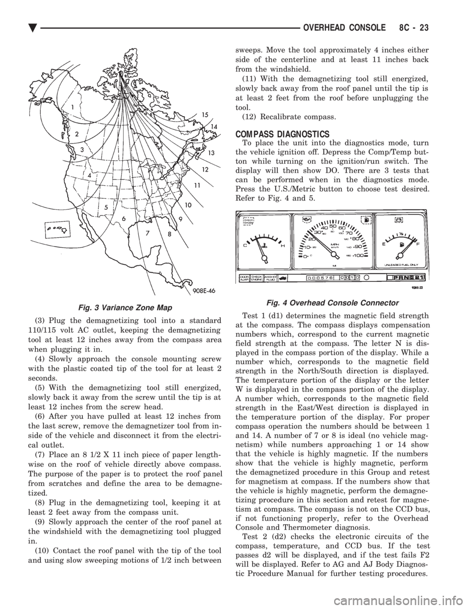
Refer to Fig. 4 and 5.
Test 1 (d1) determines the magnetic field strength
at the compass. The compass displays compensation
numbers which, correspond to the current magnetic
field strength at the compass. The letter N is dis-
played in the compass portion of the display. While a
number which, corresponds to the magnetic field
strength in the North/South direction is displayed.
The temperature portion of the display or the letter
W is displayed in the compass portion of the display.
A number which, corresponds to the magnetic field
strength in the East/West direction is displayed in
the temperature portion of the display. For proper
compass operation the numbers should be between 1
and 14. A number of 7 or 8 is ideal (no vehicle mag-
netism) while numbers approaching 1 or 14 show
that the vehicle is highly magnetic. If the numbers
show that the vehicle is highly magnetic, perform
the demagnetized procedure in this Group and retest
for magnetism at compass. If the numbers show that
the vehicle is highly magnetic, perform the demagne-
tizing procedure in this section and retest for magne-
tism at compass. The compass is not on the CCD bus,
if not functioning properly, refer to the Overhead
Console and Thermometer diagnosis. Test 2 (d2) checks the electronic circuits of the
compass, temperature, and CCD bus. If the test
passes d2 will be displayed, and if the test fails F2
will be displayed. Refer to AG and AJ Body Diagnos-
tic Procedure Manual for further testing procedures.
Fig. 3 Variance Zone MapFig. 4 Overhead Console Connector
Ä OVERHEAD CONSOLE 8C - 23
Page 546 of 2438
INSTALLATION (1) Latch switch linkage in the up position.
(2) Insert dimmer shaft into dimmer knob while
aligning switch in to switch pod assembly. (3) Install switch attaching screws.
(4) Unlatch linkage and install onto push buttons.
(5) Operate all switch modes for correct operation.
(6) Install turn signal switch.
(7) Reconnect wiring for turn signal switch, mak-
ing sure wire is properly clipped into position. (8) Place together the inner and outer bezels. In-
stall five inner switch pod panel screws and three
screws from underneath the switch pod. (9) Install turn signal lever by pushing straight
into switch assembly. (10) Install switch pod assembly.
LOWER STEERING COLUMN COVER REMOVAL
(1) Remove screws along top edge of cover.
(2) Remove screw at each lower corner of cover. (3) Remove cover from underneath over column
cover. (4) For installation reverse above procedures.
GLOVEBOX MODULE REMOVAL
(1) Disconnect battery negative cable and isolate
or remove fuse #26 prior to removing switch or wires
may short to ground. (2) Remove cowl side trim panel.
(3) Remove screws at right end of glovebox and
lower corners. (4) Open glovebox, remove light and disconnect
wiring. (5) Remove five screws along top of glovebox frame
and screw at each lower corner. (6) Remove glovebox assembly.
(7) For installation reverse above procedures.
CONCEALED HEADLAMP MODULE REMOVAL
(1) Remove left under panel silencer.
(2) Slide module off bayonet bracket while disen-
gaging spring retainer. (3) Disconnect wiring terminal.
(4) For installation reverse above procedures.
HOOD RELEASE REMOVE
(1) Remove lower column cover.
(2) Remove screws on fuse block and move aside.
(3) Remove screws on hood release assembly to re-
move. (4) For installation reverse above procedures.
AIR CONDITIONING CONTROL REMOVE
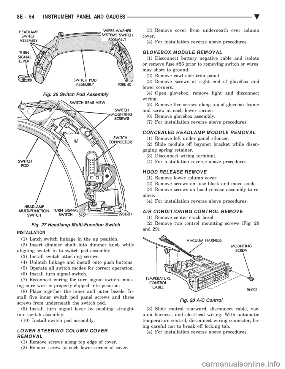
(1) Remove center stack bezel.
(2) Remove two control mounting screws (Fig. 28
and 29).
(3) Slide control rearward, disconnect cable, vac-
uum harness, and electrical wiring. With automatic
temperature control, disconnect wiring connector; be-
ing careful not to break off locking tab. (4) For installation reverse above procedures.
Fig. 26 Switch Pod Assembly
Fig. 27 Headlamp Multi-Function Switch
Fig. 28 A/C Control
8E - 54 INSTRUMENT PANEL AND GAUGES Ä
Page 614 of 2438
TESTING PROCEDURES
MULTI-FUNCTION SWITCH TESTS AA, AC, AP, AND AY BODIES
The multi-function switch contains electrical cir-
cuitry for turn signal, cornering lamps (optional),
hazard warning, headlamp beam select, headlamp
optical horn, windshield wiper, pulse wipe, and wind-
shield washer switching. This integrated switch as-
sembly is mounted to the left hand side of the
steering column. Should any function of the switch
fail, the entire switch assembly must be replaced. Re-
fer to Fig. 1 for diagnosis. To test the switch, first disconnect the negative
battery cable, then remove the upper and lower col-
umn covers to gain access to the switch connector.
Remove switch connector. Using an ohmmeter, test
for continuity (no resistance) between the terminals
of the switch as shown in the following continuity
charts (Fig 2 or 3).
DUAL-FUNCTION SWITCH TESTSÐAG AND AJ BODIES
The dual-function switch contains electrical cir-
cuitry for hazard warning switching, and circuitry
and electronics for turn signal cancellation. The
switch assembly is mounted to the left hand side of
the steering column. To test the hazard warning portion of the switch,
first disconnect the negative battery cable, then re-
move the upper and lower steering column covers to
gain access to the switch connector. Remove switch
connector (Fig. 4). Using an ohmmeter, test for con-
tinuity between the terminals of the switch as shown
in the following continuity chart (Fig. 5). To test the cancellation portion of the switch:
(1) Reconnect battery and switch connector (Fig.
5). (2) Connect voltmeter positive lead (+) to pin 8
and negative lead (-) to ground. (3) Place ignition switch to the ON position. Volt-
meter should read battery voltage. If no voltage is
present, check feed wire to pin 8. If battery voltage is
present continue with switch test.
RIGHT CANCELLATION TEST (1) Connect one side of a jumper wire to pin 3 and
the other end of jumper wire to ground. (2) Connect the positive lead (+) of a voltmeter to
pin 5 and the negative lead (-) to ground.
CAUTION: Do not allow pin 5 to become grounded
during test, switch failure will result.
(3) With the ignition switch in the ON position,
push the cancellation pawl down and read the volt-
meter. (4) The voltmeter should show at least 9 volts. (5) If voltage is 0 to 8 volts the cancellation switch
is defective. If voltage is 9 volts or more the cancel-
lation switch is working correctly.
LEFT CANCELLATION TEST
(1) Connect one side of a jumper wire to pin 4 and
the other end of jumper wire to ground. (2) Connect the positive lead (+) of a voltmeter to
pin 5 and the negative lead (-) to ground.
CAUTION: Do not allow pin 5 to become grounded
during test, switch failure will result.
(3) With the ignition switch in the ON position,
push the cancellation pawl up and read the voltme-
ter. (4) The voltmeter should show at least 9 volts.
(5) If voltage is 0 to 8 volts the cancellation switch
is defective. If voltage is 9 volts or more the cancel-
lation switch is working correctly.
REMOTE TURN SIGNAL SWITCH TESTÐAA AND AJ BODIES
The remote turn signal switch is located on the left
side of the instrument panel switch pod. To test, re-
move switch pod assembly from instrument panel.
Using an ohmmeter, test for continuity between the
terminals of the switch as shown in the following
continuity chart (Fig. 6). The white 7 way connector
next to the 14 way connector must be connected
when performing continuity checks.
CANCELLATION SOLENOID TESTÐAG AND AJ BODIES
To test the turn signal cancellation solenoid:
(1) Remove switch pod from instrument panel.
(2) Connect one end of a jumper wire to the posi-
tive terminal of the battery, the other end to pin 6 of
the turn signal switch 14 way connector. (3) Place turn signal switch in the left turn mode.
(4) Take a second jumper wire and connect one end
to a good ground. Momentarily touch the other end of
the jumper wire to pin 11 or 14. The solenoid should
energize, and return the switch to its center OFF po-
sition. (5) Place turn signal switch in the right turn
mode. (6) Repeat step 4. The solenoid should energize,
and return the switch to its center OFF position. (7) If switch does not return to center in either di-
rection, the switch is defective.
MULTI-FUNCTION SWITCHÐAA, AC, AP AND AY
BODIES
REMOVAL
(1) Disconnect negative battery cable.
(2) Tilt column only remove tilt lever.
8J - 2 TURN SIGNALS AND HAZARD WARNING FLASHER Ä
Page 621 of 2438
WINDSHIELD WIPER AND WASHER SYSTEMS
CONTENTS
page page
GENERAL WIPER INFORMATION ........... 1
INTERMITTENT WINDSHIELD WIPER MOTOR AND SWITCH SERVICE PROCEDURES .... 12
WINDSHIELD WASHERS ................. 17 WINDSHIELD WIPER BLADE AND ARM SERVICE
PROCEDURES ......................... 1
WINDSHIELD WIPER MOTOR AND LINKAGE ASSEMBLY SERVICE PROCEDURES ....... 3
GENERAL WIPER INFORMATION
WARNING: ON VEHICLES EQUIPPED WITH AIR-
BAG, SEE GROUP 8M, RESTRAINT SYSTEMS FOR
STEERING WHEEL OR COLUMN REMOVAL PROCE-
DURES.
The windshield wipers can be operated with the
windshield wiper switch only when the ignition
switch is in the ACCESSORY or IGNITION position.
A fuse, located in the fuse block, protects the cir-
cuitry of the wiper system and the vehicle. The wiper motor has permanent magnet fields. The speeds are determined by current flow to the appro-
priate set of brushes. The intermittent wipe system, in addition to low
and high speed, has a delay mode. The delay mode
has a range of 2 to 15 seconds. This is accomplished
by a variable resistor in the wiper switch and is con-
trolled electrically by a relay. The wiper system completes the wipe cycle when
the switch is turned OFF. The blades park in the
lowest portion of the wipe pattern.
WINDSHIELD WIPER BLADE AND ARM SERVICE PROCEDURES
WIPER BLADES
Wiper blades, exposed to the weather for a long pe-
riod of time, tend to lose their wiping effectiveness.
Periodic cleaning of the wiper blade is suggested to
remove the accumulation of salt and road film. The
wiper blades, arms, and windshield should be cleaned
with a sponge or cloth and a mild detergent or nona-
brasive cleaner. If the blades continue to streak or
smear, they should be replaced.
WIPER BLADE ELEMENT CHANGE
(1) Turn wiper switch ON, position blades to a con-
venient place by turning the ignition switch ON and
OFF. (2) Lift wiper arm to raise blade off glass.
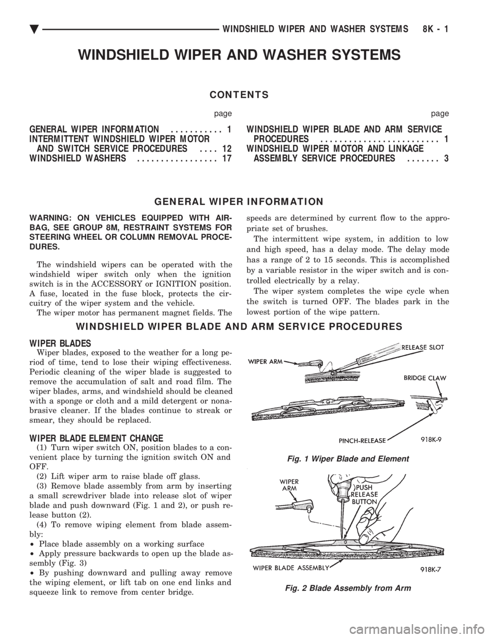
(3) Remove blade assembly from arm by inserting
a small screwdriver blade into release slot of wiper
blade and push downward (Fig. 1 and 2), or push re-
lease button (2). (4) To remove wiping element from blade assem-
bly:
² Place blade assembly on a working surface
² Apply pressure backwards to open up the blade as-
sembly (Fig. 3)
² By pushing downward and pulling away remove
the wiping element, or lift tab on one end links and
squeeze link to remove from center bridge.
Fig. 1 Wiper Blade and Element
Fig. 2 Blade Assembly from Arm
Ä WINDSHIELD WIPER AND WASHER SYSTEMS 8K - 1
Page 632 of 2438
INTERMITTENT WINDSHIELD WIPER MOTOR AND SWITCH SERVICE PROCEDURES
INDEX
page page
Intermittent Windshield Wiper Switch Tests ..... 12
Intermittent Wipe Switch Test ............... 14
Intermittent Wiper Function Tests ............ 14
Intermittent Wiper Motor System Test ......... 12 Pulse Intermittent Windshield Wiper Controller
(PIWWC) .............................. 15
Standard Wiper Switch Test ................ 14
Wiper Switch Service Procedure ............. 15
INTERMITTENT WIPER MOTOR SYSTEM TEST
Intermittent Wiper Motor Service Procedures for
diagnosis of problems which do not involve the delay
function, refer to the Two-Speed Motor Function
Tests. The two-speed functions of all wiper motors
are identical. If a problem occurs, only in the DELAY mode, the
following tests are to be performed.
INTERMITTENT WINDSHIELD WIPER SWITCH
TESTS
WARNING: ON VEHICLES EQUIPPED WITH AIR-
BAG, SEE GROUP 8M, RESTRAINT SYSTEMS FOR
STEERING WHEEL OR COLUMN REMOVAL PROCE-
DURES.
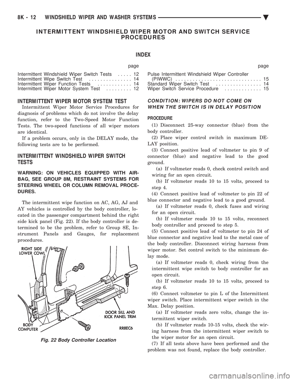
The intermittent wipe function on AC, AG, AJ and
AY vehicles is controlled by the body controller, lo-
cated in the passenger compartment behind the right
side kick panel (Fig. 22). If the body controller is de-
termined to be the problem, refer to Group 8E, In-
strument Panels and Gauges, for replacement
procedures.
CONDITION: WIPERS DO NOT COME ON WHEN THE SWITCH IS IN DELAY POSITION
PROCEDURE
(1) Disconnect 25-way connector (blue) from the
body controller. (2) Place wiper control switch in maximum DE-
LAY position. (3) Connect positive lead of voltmeter to pin 9 of
connector (blue) and negative lead to the good
ground. (a) If voltmeter reads 0, check control switch and
wiring for an open circuit. (b) If voltmeter reads 10 to 15 volts, proceed to
step 4.
(4) Connect positive lead of voltmeter to pin 22 of
blue connector and negative lead to a good ground. (a) If voltmeter reads 0, check fuses and wiring
for an open circuit. (b) If voltmeter reads 10 to 15 volts, reconnect
body controller and proceed to step 5.
(5) Connect positive lead of voltmeter to pin 24 of
blue connector and negative lead to the metal case of
the body controller. Disconnect wiring harness from
wiper motor. Set control switch to the minimum de-
lay mode. (a) If voltmeter reads 0, check wiring from the
intermittent wipe switch to body controller for an
open circuit. (b) If voltmeter reads 10 to 15 volts, proceed to
step 6.
(6) Connect voltmeter to pin L of the Intermittent
wiper switch. Place intermittent wiper switch in the
Max. Delay position. (a) If voltmeter reads zero volts, change the in-
termittent wiper switch. (b) If voltmeter reads 10-15 volts, check the wir-
ing harness from the intermittent wiper switch to
the wiper motor for an open circuit.
(7) If all tests above have been performed and the
problem was not found, replace the body controller.
Fig. 22 Body Controller Location
8K - 12 WINDSHIELD WIPER AND WASHER SYSTEMS Ä
Page 633 of 2438
CONDITION: WIPERS START TO WIPE, BUT STOP BEFORE ONE COMPLETE CYCLE ANDDO NOT RETURN TO PARK POSITION
PROCEDURE
(1) Verify that motor will park when the column
switch is put in the OFF position. (2) Set wiper control switch to maximum DELAY
and allow motor to run until it stops during the wipe
cycle. When motor stops, disconnect 25-way blue con-
nector from the body controller. (3) Connect positive lead of voltmeter to pin 20 of
blue connector and negative lead to the metal case of
the body controller. (a) If voltmeter reads 0, check wiring for an open
circuit. (b) If voltmeter reads 10 to 15 volts, proceed to
step 4.
(4) Using an ohmmeter or continuity tester; (a) Check for continuity between pins 20 and 24
of blue connector of the body controller. (b) Reverse ohmmeter leads on pins 20 and 24,
again checking for continuity. (c) If continuity between pins 20 and 24 is not
observed in both steps a and b, replace the body
controller.
CONDITION: EXCESSIVE DELAY OF MORE THAN 30 SECONDS OR INADEQUATEVARIATION IN DELAY
PROCEDURE
(1) Variations in delay should be as follows: (a) Minimum delay control to extreme counter-
clockwise position before first detent of 1/2 to 2 sec-
onds. (b) Maximum delay control to extreme clockwise
position before OFF detent of 15 to 25 seconds.
(2) If there is excessive delay or no variations in
delay, remove the wiper motor wiring harness while
the motor is parked in the OFF position. (3) Remove 25-way blue connector from the body
controller. (4) Set wiper control switch to maximum DELAY
position. (5) With ignition switch in ON position, measure
voltage between pin 9 of black connector and a good
ground. (a) If voltmeter reads 0, proceed to step 6.
(b) If voltmeter reads 10 to 15 volts, proceed to
step 7.
(6) Set wiper control switch to minimum DELAY
position and measure voltage between pin 9 of blue
connector and a good ground. If voltmeter reads 0,
check for an open circuit in the intermittent wipe
wiring harness. (7) Remove wiper motor circuit fuse. (8) Using an ohmmeter, measure the resistance be-
tween pins 9 and 22 of the body controller 25-way
black connector. Set the wiper control switch first to
minimum DELAY and then maximum DELAY. (a) If resistance reading at minimum DELAY
setting is between 0 and 15 ohms, and at maxi-
mum DELAY setting the resistance is between
240,000 and 400,000 ohms, replace the body con-
troller. (b) If the resistance values above are not ob-
tained, replace the wiper control switch.
CONDITION: WIPERS DO NOT RUN CONTINUALLY WHEN WASH CONTROL ISOPERATED DURING DELAY MODE
PROCEDURE
(1) Disconnect 25-way blue connector from the
body controller (2) Using a voltmeter, connect the positive lead to
pin 10 of the (Black) connector. Connect negative
lead to the body computer metal case. (3) Set wiper control switch to DELAY position.
(4) Depress wash switch.
(5) If voltage reads 0, check switch relay and wir-
ing. (6) If voltage is between 10 and 15 volts, the prob-
lem is in the body controller.
CONDITION: IN DELAY MODE, WIPERS RUN CONTINUALLY WHEN WASH IS OPERATEDBUT DO NOT PROVIDE FOUR EXTRA WIPESWHEN WASH CONTROL IS RELEASED
PROCEDURE
Replace body controller.
CONDITION: WIPERS START ERRATICALLY DURING DELAY MODE
PROCEDURE
(1) Verify that the ground connection at the in-
strument panel is making a good connection, free
from paint and is tight. (2) Verify that the motor ground strap is making
good contact and that the motor mounting bolts are
tight. (3) Verify that the wiring connections to the body
controller, wiper motor, and wiper motor switch are
tight and free of corrosion. (4) If condition is not corrected, problem is with
the body controller
Ä WINDSHIELD WIPER AND WASHER SYSTEMS 8K - 13
Page 634 of 2438
INTERMITTENT WIPER FUNCTION TESTS
CONDITION: EXCESSIVE DELAY OF MORE THAN 30 SECONDS OR INADEQUATEVARIATION IN DELAY
PROCEDURE
Variations in delay should be as follows:
(1) Minimum delay control to extreme counter-
clockwise position before first detent of one half to
two seconds. (2) Maximum delay control to extreme clockwise
position before off detent of ten to thirty seconds. (3) If there is excessive delay or no variations in
delay proceed to intermittent wipe switch test.
CONDITION: IN DELAY MODE WIPERS RUN CONTINUALLY WHEN WASH IS OPERATEDBUT DO NOT PROVIDE AN EXTRA WIPEWHEN THE WASH CONTROL IS RELEASED
PROCEDURE
Replace the control unit.
CONDITION: WIPERS START ERRATICALLY DURING DELAY MODE
PROCEDURE
(1) Verify that the ground connection at the in-
strument panel is making good connection, free from
paint and is tight. (2) Verify that the motor ground strap is making
good contact and that the motor mounting bolts are
tight. (3) Verify that the wiring ground connections for
the intermittent wipe control unit and the wiper
switch are tight. (4) If condition is not corrected, replace control
unit.
STANDARD WIPER SWITCH TEST
AP BODY
To test the switch, first disconnect the switch wires
from the body wiring in the steering column. Using
an ohmmeter, test for continuity between the termi-
nals of the switch, as indicated in the following con-
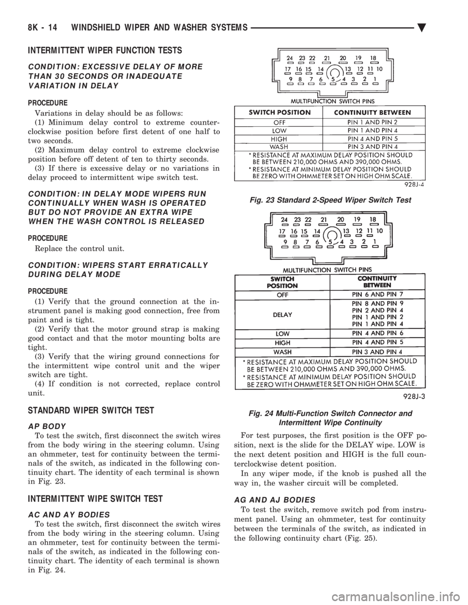
tinuity chart. The identity of each terminal is shown
in Fig. 23.
INTERMITTENT WIPE SWITCH TEST
AC AND AY BODIES
To test the switch, first disconnect the switch wires
from the body wiring in the steering column. Using
an ohmmeter, test for continuity between the termi-
nals of the switch, as indicated in the following con-
tinuity chart. The identity of each terminal is shown
in Fig. 24. For test purposes, the first position is the OFF po-
sition, next is the slide for the DELAY wipe. LOW is
the next detent position and HIGH is the full coun-
terclockwise detent position. In any wiper mode, if the knob is pushed all the
way in, the washer circuit will be completed.
AG AND AJ BODIES
To test the switch, remove switch pod from instru-
ment panel. Using an ohmmeter, test for continuity
between the terminals of the switch, as indicated in
the following continuity chart (Fig. 25).
Fig. 23 Standard 2-Speed Wiper Switch Test
Fig. 24 Multi-Function Switch Connector and Intermittent Wipe Continuity
8K - 14 WINDSHIELD WIPER AND WASHER SYSTEMS Ä
Page 691 of 2438
REAR WINDOW DEFOGGER
CONTENTS
page page
CONTROL SWITCH/TIMER RELAY MODULE . . 1
GENERAL INFORMATION .................. 1REPAIR GRID LINES, TERMINALS AND PIGTAILS.3
SERVICE PROCEDURES ................... 1
GENERAL INFORMATION
For proper operation of the Rear Window Defogger
system refer to the Owner's Manual. Vehicles equipped with an electrically heated rear
window defogger also have a 40/90 amp generator. The system consists of a rear glass with two verti-
cal bus bars and a series of electrically connected
grid lines fired on the inside surface. A control
switch and a timer relay combined into a single as-
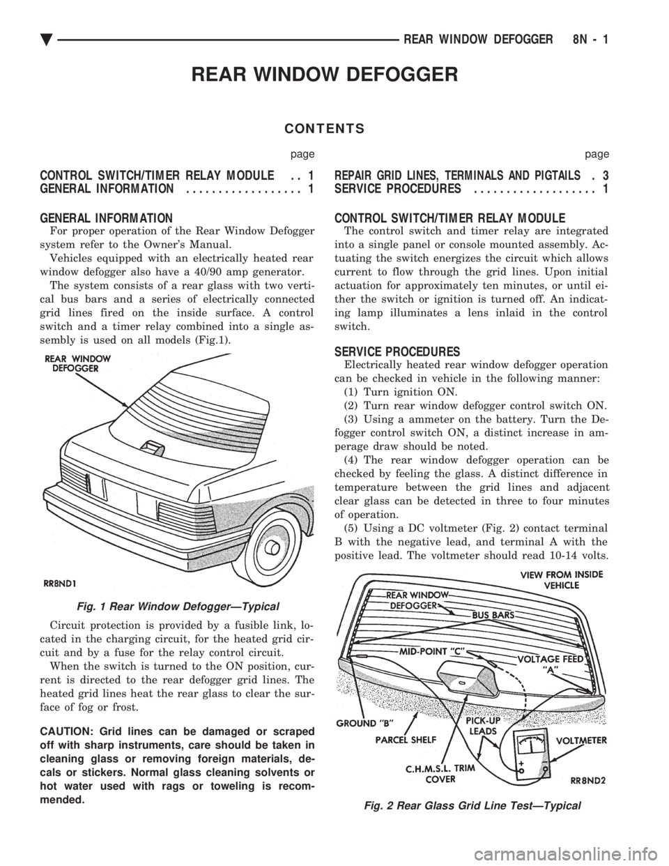
sembly is used on all models (Fig.1).
Circuit protection is provided by a fusible link, lo-
cated in the charging circuit, for the heated grid cir-
cuit and by a fuse for the relay control circuit. When the switch is turned to the ON position, cur-
rent is directed to the rear defogger grid lines. The
heated grid lines heat the rear glass to clear the sur-
face of fog or frost.
CAUTION: Grid lines can be damaged or scraped
off with sharp instruments, care should be taken in
cleaning glass or removing foreign materials, de-
cals or stickers. Normal glass cleaning solvents or
hot water used with rags or toweling is recom-
mended.
CONTROL SWITCH/TIMER RELAY MODULE
The control switch and timer relay are integrated
into a single panel or console mounted assembly. Ac-
tuating the switch energizes the circuit which allows
current to flow through the grid lines. Upon initial
actuation for approximately ten minutes, or until ei-
ther the switch or ignition is turned off. An indicat-
ing lamp illuminates a lens inlaid in the control
switch.
SERVICE PROCEDURES
Electrically heated rear window defogger operation
can be checked in vehicle in the following manner: (1) Turn ignition ON.
(2) Turn rear window defogger control switch ON.
(3) Using a ammeter on the battery. Turn the De-
fogger control switch ON, a distinct increase in am-
perage draw should be noted. (4) The rear window defogger operation can be
checked by feeling the glass. A distinct difference in
temperature between the grid lines and adjacent
clear glass can be detected in three to four minutes
of operation. (5) Using a DC voltmeter (Fig. 2) contact terminal
B with the negative lead, and terminal A with the
positive lead. The voltmeter should read 10-14 volts.
Fig. 1 Rear Window DefoggerÐTypical
Fig. 2 Rear Glass Grid Line TestÐTypical
Ä REAR WINDOW DEFOGGER 8N - 1
Page 699 of 2438
to the deck lid open position. If the pull down limit
switch is depressed at this time, the motor should
stop.(c) If these results are not obtained, replace the
pull down motor assembly.
REMOTE KEYLESS ENTRY
OPERATION
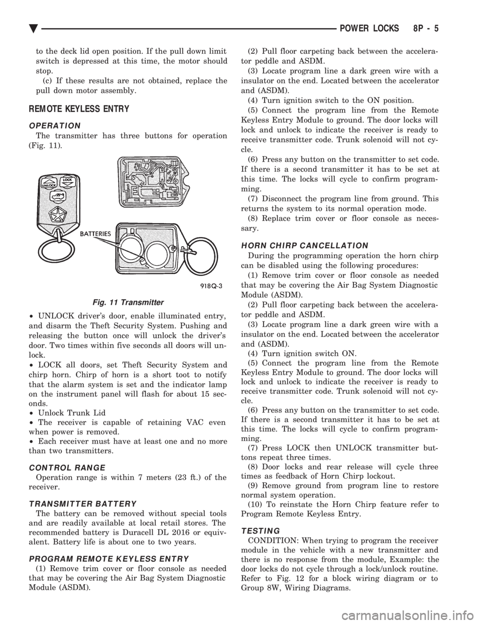
The transmitter has three buttons for operation
(Fig. 11).
² UNLOCK driver's door, enable illuminated entry,
and disarm the Theft Security System. Pushing and
releasing the button once will unlock the driver's
door. Two times within five seconds all doors will un-
lock.
² LOCK all doors, set Theft Security System and
chirp horn. Chirp of horn is a short toot to notify
that the alarm system is set and the indicator lamp
on the instrument panel will flash for about 15 sec-
onds.
² Unlock Trunk Lid
² The receiver is capable of retaining VAC even
when power is removed.
² Each receiver must have at least one and no more
than two transmitters.
CONTROL RANGE
Operation range is within 7 meters (23 ft.) of the
receiver.
TRANSMITTER BATTERY
The battery can be removed without special tools
and are readily available at local retail stores. The
recommended battery is Duracell DL 2016 or equiv-
alent. Battery life is about one to two years.
PROGRAM REMOTE KEYLESS ENTRY
(1) Remove trim cover or floor console as needed
that may be covering the Air Bag System Diagnostic
Module (ASDM). (2) Pull floor carpeting back between the accelera-
tor peddle and ASDM. (3) Locate program line a dark green wire with a
insulator on the end. Located between the accelerator
and (ASDM). (4) Turn ignition switch to the ON position.
(5) Connect the program line from the Remote
Keyless Entry Module to ground. The door locks will
lock and unlock to indicate the receiver is ready to
receive transmitter code. Trunk solenoid will not cy-
cle. (6) Press any button on the transmitter to set code.
If there is a second transmitter it has to be set at
this time. The locks will cycle to confirm program-
ming. (7) Disconnect the program line from ground. This
returns the system to its normal operation mode. (8) Replace trim cover or floor console as neces-
sary.
HORN CHIRP CANCELLATION
During the programming operation the horn chirp
can be disabled using the following procedures: (1) Remove trim cover or floor console as needed
that may be covering the Air Bag System Diagnostic
Module (ASDM). (2) Pull floor carpeting back between the accelera-
tor peddle and ASDM. (3) Locate program line a dark green wire with a
insulator on the end. Located between the accelerator
and (ASDM). (4) Turn ignition switch ON.
(5) Connect the program line from the Remote
Keyless Entry Module to ground. The door locks will
lock and unlock to indicate the receiver is ready to
receive transmitter code. Trunk solenoid will not cy-
cle. (6) Press any button on the transmitter to set code.
If there is a second transmitter it has to be set at
this time. The locks will cycle to confirm program-
ming. (7) Press LOCK then UNLOCK transmitter but-
tons repeat three times. (8) Door locks and rear release will cycle three
times as feedback of Horn Chirp lockout. (9) Remove ground from program line to restore
normal system operation. (10) To reinstate the Horn Chirp feature refer to
Program Remote Keyless Entry.
TESTING
CONDITION: When trying to program the receiver
module in the vehicle with a new transmitter and
there is no response from the module, Example: the
door locks do not cycle through a lock/unlock routine.
Refer to Fig. 12 for a block wiring diagram or to
Group 8W, Wiring Diagrams.
Fig. 11 Transmitter
Ä POWER LOCKS 8P - 5