air suspension CHEVROLET DYNASTY 1993 Owner's Manual
[x] Cancel search | Manufacturer: CHEVROLET, Model Year: 1993, Model line: DYNASTY, Model: CHEVROLET DYNASTY 1993Pages: 2438, PDF Size: 74.98 MB
Page 119 of 2438
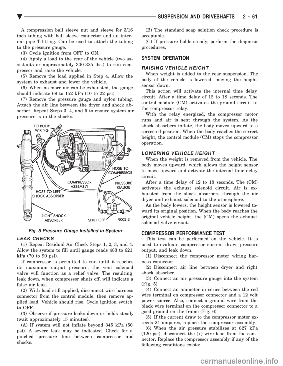
A compression ball sleeve nut and sleeve for 3/16
inch tubing with ball sleeve connector and an inter-
nal pipe T-fitting. Can be used to attach the tubing
to the pressure gauge. (3) Cycle ignition from OFF to ON.
(4) Apply a load to the rear of the vehicle (two as-
sistants or approximately 300-325 lbs.) to run com-
pressor and raise the vehicle. (5) Remove the load applied in Step 4. Allow the
system to exhaust and lower the vehicle. (6) When no more air can be exhausted, the gauge
should indicate 69 to 152 kPa (10 to 22 psi). (7) Remove the pressure gauge and nylon tubing.
Attach the air line between the dryer and shock ab-
sorber. Repeat Steps 3, 4, and 5 to ensure system air
pressure is in the shocks.
LEAK CHECKS
(1) Repeat Residual Air Check Steps 1, 2, 3, and 4.
Allow the system to fill until gauge reads 483 to 621
kPa (70 to 90 psi). If compressor is permitted to run until it reaches
its maximum output pressure, the vent solenoid
valve will function as a relief valve. The resulting
leak down, when compressor shuts off, will indicate a
false air leak. (2) With load still applied, disconnect wire harness
connector from the control module, then remove ap-
plied load. Vehicle should rise. Cycle ignition switch
to OFF. (3) Observe if pressure leaks down or holds steady
(wait approximately 15 minutes). (A) If system will not inflate beyond 345 kPa (50
psi). A severe leak may be indicated. Check for a
pinched pressure line between compressor and
shocks. (B) The standard soap solution check procedure is
acceptable. (C) If pressure holds steady, perform the diagnosis
procedures.
SYSTEM OPERATION
RAISING VEHICLE HEIGHT
When weight is added to the rear suspension. The
body of the vehicle is lowered, moving the height
sensor down. This action will activate the internal time delay
circuit. After a time delay of 12 to 18 seconds. The
control module (CM) activates the ground circuit to
the compressor relay. With the relay energized, the compressor motor
runs and air is sent through the system. As the
shock absorbers inflate, the body moves upward to a
corrected position. When the body reaches the correct
height, the control module (CM) stops the compressor
operation.
LOWERING VEHICLE HEIGHT
When the weight is removed from the vehicle. The
body moves upward, which allows the height sensor
to move upward and activate the internal time delay
circuit. After a time delay of 12 to 18 seconds. The (CM)
activates the exhaust solenoid circuit. Air is ex-
hausted from the shock absorbers through the air
dryer and exhaust solenoid to the atmosphere. As the body lowers, the height sensor is lowered to-
ward its original position. When the body reaches the
original vehicle height, the (CM) opens the exhaust
solenoid valve circuit.
COMPRESSOR PERFORMANCE TEST
This test can be performed on the vehicle. It is
used to evaluate compressor current draw, pressure
output, and leak down. (1) Disconnect the compressor motor wiring har-
ness connector. (2) Disconnect air line between dryer and right
shock absorber. (3) Connect an air pressure gauge into the system
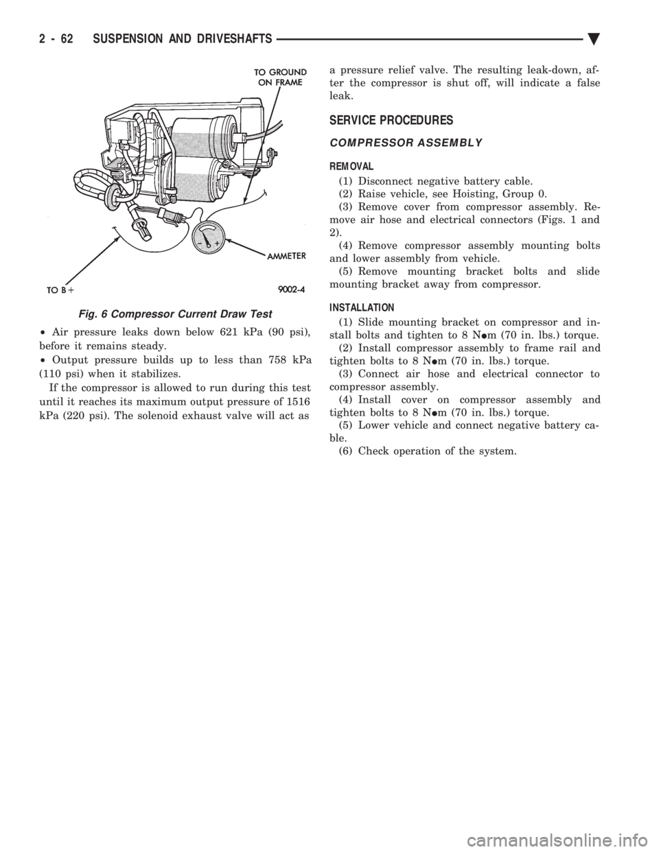
(Fig. 5). (4) Connect an ammeter in series between the red
wire terminal on compressor connector and a 12 volt
power source. Also, connect a ground wire from the
black wire terminal on the compressor connector to a
good ground on the frame (Fig. 6). (5) If the current draw to the compressor motor ex-
ceeds 21 amperes, replace the compressor assembly. (6) When the air pressure stabilizes at 827 kPa
(120 psi), disconnect the (+) wire lead from the con-
nector. Replace the compressor assembly if any of the
following conditions exists:
Fig. 5 Pressure Gauge Installed in System
Ä SUSPENSION AND DRIVESHAFTS 2 - 61
Page 120 of 2438
² Air pressure leaks down below 621 kPa (90 psi),
before it remains steady.
² Output pressure builds up to less than 758 kPa
(110 psi) when it stabilizes. If the compressor is allowed to run during this test
until it reaches its maximum output pressure of 1516
kPa (220 psi). The solenoid exhaust valve will act as a pressure relief valve. The resulting leak-down, af-
ter the compressor is shut off, will indicate a false
leak.
SERVICE PROCEDURES
COMPRESSOR ASSEMBLY
REMOVAL
(1) Disconnect negative battery cable.
(2) Raise vehicle, see Hoisting, Group 0.
(3) Remove cover from compressor assembly. Re-
move air hose and electrical connectors (Figs. 1 and
2). (4) Remove compressor assembly mounting bolts
and lower assembly from vehicle. (5) Remove mounting bracket bolts and slide
mounting bracket away from compressor.
INSTALLATION (1) Slide mounting bracket on compressor and in-
stall bolts and tighten to 8 N Im (70 in. lbs.) torque.
(2) Install compressor assembly to frame rail and
tighten bolts to 8 N Im (70 in. lbs.) torque.
(3) Connect air hose and electrical connector to
compressor assembly. (4) Install cover on compressor assembly and
tighten bolts to 8 N Im (70 in. lbs.) torque.
(5) Lower vehicle and connect negative battery ca-
ble. (6) Check operation of the system.
Fig. 6 Compressor Current Draw Test
2 - 62 SUSPENSION AND DRIVESHAFTS Ä
Page 121 of 2438
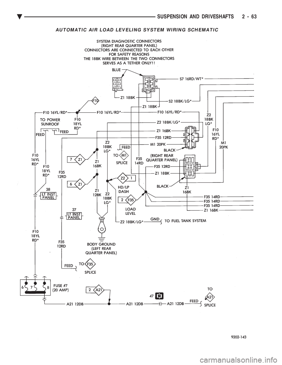
AUTOMATIC AIR LOAD LEVELING SYSTEM WIRING SCHEMATIC
Ä SUSPENSION AND DRIVESHAFTS 2 - 63
Page 122 of 2438
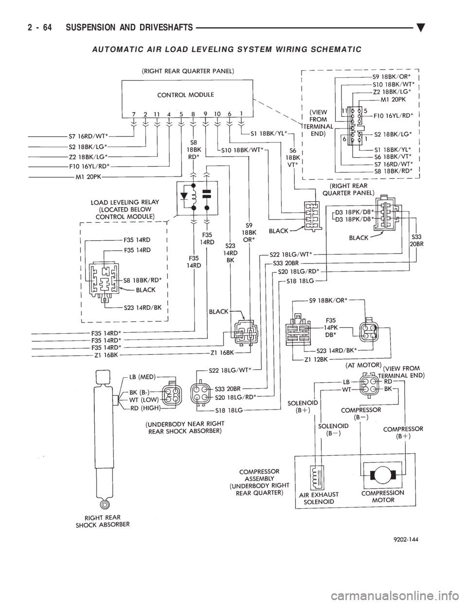
AUTOMATIC AIR LOAD LEVELING SYSTEM WIRING SCHEMATIC
2 - 64 SUSPENSION AND DRIVESHAFTS Ä
Page 123 of 2438
REAR LEVELING DIAGNOSTIC PROCEDURES
SELF-DIAGNOSTICS
A self-diagnostic procedure is available for the ser-
vice technician to use to detect system malfunctions.
BEFORE DIAGNOSTICS TEST
Check the 20 amp fuse (position W40) and the 30
amp circuit breaker (position W5) to be assured they
are functional components. Check all connectors that link the system into the
main body wiring harness. These include compressor,
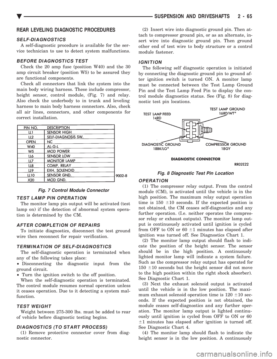
height sensor, control module, (Fig. 7) and relay.
Also check the underbody to in trunk and leveling
harness to main body harness connectors. Also, check
all air lines, connectors, and other components for
correct installation.
TEST LAMP PIN OPERATION
The monitor lamp pin output will be activated (test
lamp on) if the detection of abnormal system opera-
tion is determined by the CM.
AFTER COMPLETION OF REPAIRS
To initiate diagnostics, disconnect the test ground
wire then reconnect for repair verification.
TERMINATION OF SELF-DIAGNOSTICS
The self-diagnostic operation is terminated when
any of the following takes place:
² Disconnecting the diagnostic input from the
ground circuit.
² Turn the ignition switch to the off position.
When the self-diagnostic operation is terminated.
The control module resumes normal operation unless
it ceases operation. Due to it detecting a system mal-
function.
TEST WEIGHT
Weight between 275-300 lbs. must be added to rear
of vehicle before diagnostic testing begins.
DIAGNOSTICS (TO START PROCESS)
(1) Remove protective connector cover from diag-
nostic connector. (2) Insert wire into diagnostic ground pin. Then at-
tach to compressor ground pin, or as an alternate, in-
sert wire into diagnostic ground pin. Then ground
other end of test wire to body structure or a control
module fastener.
IGNITION
The following self diagnostic operation is initiated
by connecting the diagnostic ground pin to ground af-
ter ignition switch is turned ON. A monitor lamp
must be connected between the Test Lamp Ground
Pin and the Test Lamp Feed Pin to display the con-
trol module diagnostics status. See (Fig. 8) for diag-
nostic test pin locations.
OPERATION
(1) The compressor relay output. From the control
module (CM), is activated until the vehicle is in the
high position. The maximum relay output operation
time is 150 610 seconds. If the expected position is
not obtained, the CM ceases self-diagnostics and any
further operation. (I.e. neither operates the compres-
sor relay or exhaust outputs). The monitor lamp out-
put is continuously activated until ignition is cycled
from OFF to ON or 60 61 minutes has elapsed after
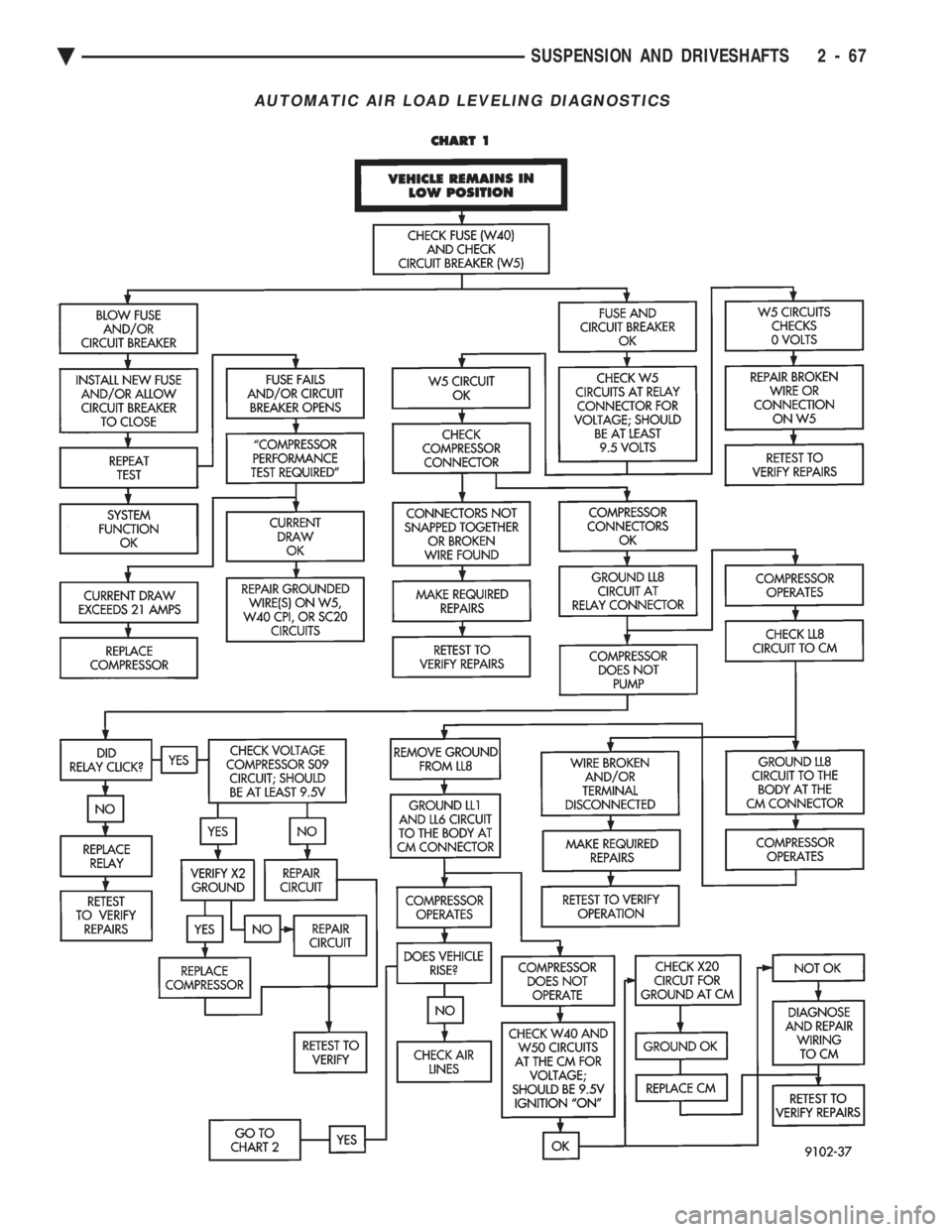
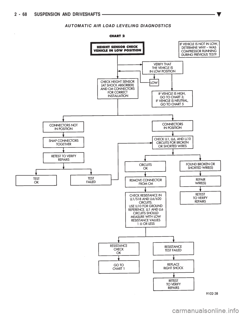
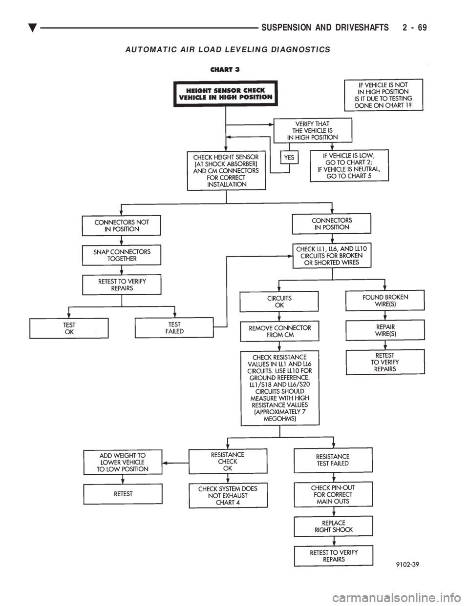
ignition was turned off. See Diagnostics Chart 1. (2) The monitor lamp output should flash to indi-
cate the position of the height sensor. The sensor
should be in the high position. A continuously
lighted monitor lamp will indicate a system failure.
Such as the compressor relay output has operated for
150 610 seconds but the height sensor did not move
to the high position within the right shock absorber).
See Diagnostic Chart 1. (3) Next the exhaust solenoid output is activated
until the vehicle is in the low position. The maxi-
mum exhaust solenoid operation time is 120 610 sec-
onds. If the expected position is not obtained, the
module ceases self-diagnostics and any further oper-
ation. The monitor lamp output is lighted continu-
ously until ignition is cycled from OFF to ON or 60
6 1 minutes has elapsed after ignition is turned off.
See Diagnostic Chart 4. (4) The monitor lamp should flash to indicate the
height sensor is in the low position. A continuouslyFig. 7 Control Module Connector
Fig. 8 Diagnostic Test Pin Location
Ä SUSPENSION AND DRIVESHAFTS 2 - 65
Page 125 of 2438
AUTOMATIC AIR LOAD LEVELING DIAGNOSTICS
Ä SUSPENSION AND DRIVESHAFTS 2 - 67
Page 126 of 2438
AUTOMATIC AIR LOAD LEVELING DIAGNOSTICS
2 - 68 SUSPENSION AND DRIVESHAFTS Ä
Page 127 of 2438
AUTOMATIC AIR LOAD LEVELING DIAGNOSTICS
Ä SUSPENSION AND DRIVESHAFTS 2 - 69
Page 128 of 2438
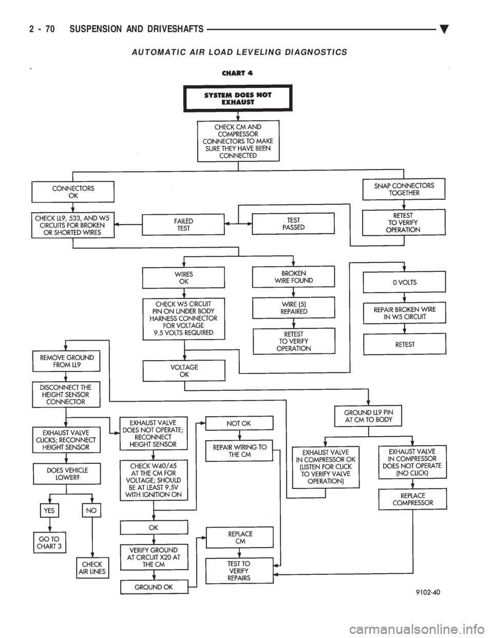
AUTOMATIC AIR LOAD LEVELING DIAGNOSTICS
2 - 70 SUSPENSION AND DRIVESHAFTS Ä
Page 129 of 2438
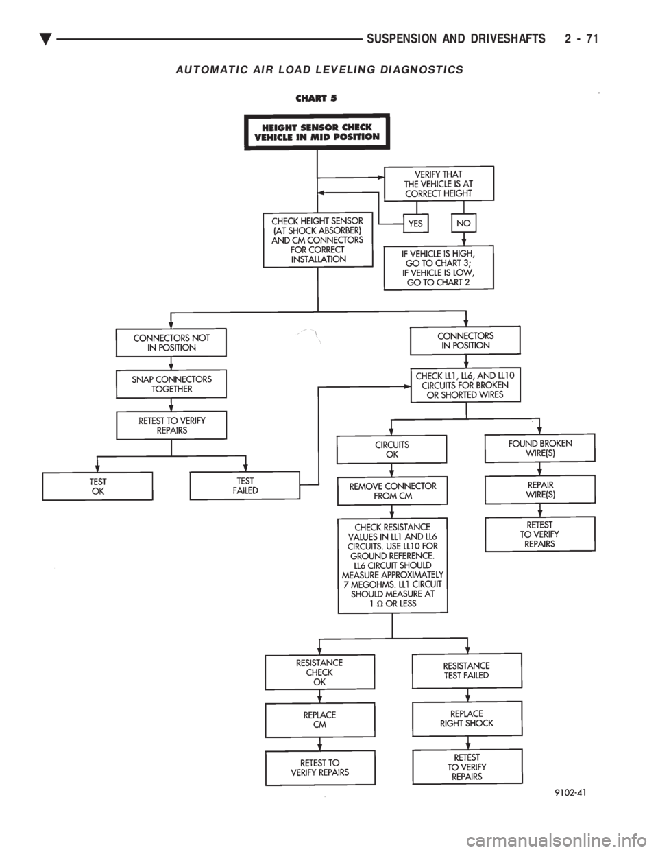
AUTOMATIC AIR LOAD LEVELING DIAGNOSTICS
Ä SUSPENSION AND DRIVESHAFTS 2 - 71