air suspension CHEVROLET DYNASTY 1993 Repair Manual
[x] Cancel search | Manufacturer: CHEVROLET, Model Year: 1993, Model line: DYNASTY, Model: CHEVROLET DYNASTY 1993Pages: 2438, PDF Size: 74.98 MB
Page 1945 of 2438
bolts and nut on locating stud (Fig. 2). The right rear
crossmember stud is a pilot that correctly locates
the crossmember. Tighten down this bolt first,
then torque all 4 crossmember fasteners to 122
N Im (90 ft. lbs.).
CAUTION: Proper torque on the crossmember to
frame rail mounting bolts is very important.
(3) Torque the 4 bolts (Fig. 3) attaching the steering
gear assembly to front crossmember, to 68 N Im (50 ft.
lbs.). To ensure proper alignment of the steering
gear tighten left front bolt first. (4) Attach the engine damper strut from the engine
to the crossmember (if so equipped). (5) Attach the fluid tubes (Fig. 3) from the power
steering pump to the fittings on the steering gear.
Torque the fluid pressure line to steering gear tube nut
to 31 N Im (275 in. lbs.).
(6) Mount the outer tie rod ends to the steering
knuckles. Install the tie rod end to steering knuckle
attaching nuts. Torque the tie rod end to steering
knuckle nuts to 52 N Im (38 ft. lbs.). Install cotter pin
in tie rod end. (7) Install the front tire and wheel assemblies on
vehicle. Install the wheel lug nuts and torque to 129
N Im (95 ft. lbs.).
(8) Lower vehicle.
CAUTION: Do not use automatic transmission fluid. (9) Fill power steering pump fluid reservoir to the
(Full-Cold) proper level. (10) Start the engine and let run for a few seconds.
Then turn the engine off.
(11) Add fluid if necessary.
(12) Raise front wheels of vehicle off the ground.
(13) Start engine and turn steering wheel several
times from stop to stop to bleed air from fluid in
system. Stop engine, check fluid level, and inspect
system for leaks. Fill pump reservoir to correct
level with Mopar t, Power Steering Fluid, or
equivalent. See Checking Fluid Level.
(14) Lower front wheels of vehicle back on the
ground. (15) Adjust toe (Refer to Group 2 Suspension).
OUTER TIE ROD
REMOVAL
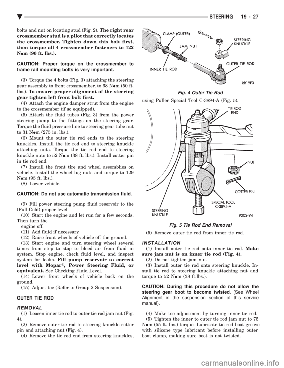
(1) Loosen inner tie rod to outer tie rod jam nut (Fig.
4). (2) Remove outer tie rod to steering knuckle cotter
pin and attaching nut (Fig. 4). (4) Remove the tie rod end from steering knuckles, using Puller Special Tool C-3894-A (Fig. 5).
(5) Remove outer tie rod from inner tie rod.
INSTALLATION
(1) Install outer tie rod onto inner tie rod. Make
sure jam nut is on inner tie rod (Fig. 4). (2) Do not tighten jam nut.
(3) Install outer tie rod onto steering knuckle. In-
stall tie rod to steering knuckle attaching nut and
torque to 52 N Im (38 ft.lbs.).
CAUTION: During this procedure do not allow the
steering gear boot to become twisted. (See Wheel
Alignment in the suspension section of this service
manual).
(4) Make toe adjustment by turning inner tie rod.
(5) Tighten the inner to outer tie rod jam nut to 75
N Im (55 ft. lbs.) torque. Lubricate tie rod boot groove
with silicone type lubricant before installing outer
boot clamp, making sure boot is not twisted.
Fig. 4 Outer Tie Rod
Fig. 5 Tie Rod End Removal
Ä STEERING 19 - 27
Page 2059 of 2438
CAUTION: If the vehicle is equipped with two oil
coolers (one in the radiator tank, one in front of the
radiator) they must be flushed separately. Do not
attempt to flush both coolers at one time. (1) Disconnect the cooler lines at the transmission.
(2) Using a hand suction gun filled with mineral
spirits, reverse flush the cooler. Force mineral spirits
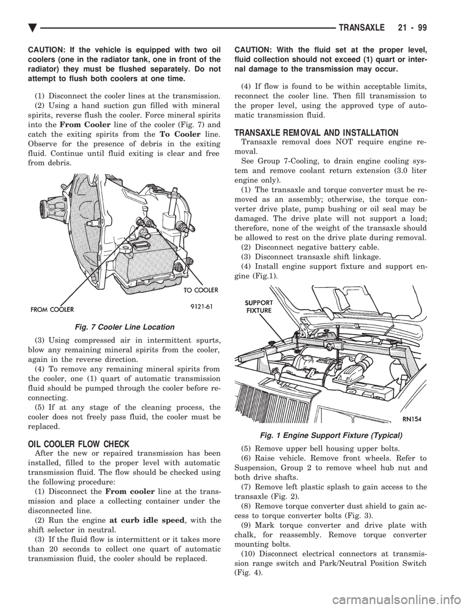
into the From Cooler line of the cooler (Fig. 7) and
catch the exiting spirits from the To Coolerline.
Observe for the presence of debris in the exiting
fluid. Continue until fluid exiting is clear and free
from debris.
(3) Using compressed air in intermittent spurts,
blow any remaining mineral spirits from the cooler,
again in the reverse direction. (4) To remove any remaining mineral spirits from
the cooler, one (1) quart of automatic transmission
fluid should be pumped through the cooler before re-
connecting. (5) If at any stage of the cleaning process, the
cooler does not freely pass fluid, the cooler must be
replaced.
OIL COOLER FLOW CHECK
After the new or repaired transmission has been
installed, filled to the proper level with automatic
transmission fluid. The flow should be checked using
the following procedure: (1) Disconnect the From coolerline at the trans-
mission and place a collecting container under the
disconnected line. (2) Run the engine at curb idle speed , with the
shift selector in neutral. (3) If the fluid flow is intermittent or it takes more
than 20 seconds to collect one quart of automatic
transmission fluid, the cooler should be replaced. CAUTION: With the fluid set at the proper level,
fluid collection should not exceed (1) quart or inter-
nal damage to the transmission may occur.
(4) If flow is found to be within acceptable limits,
reconnect the cooler line. Then fill transmission to
the proper level, using the approved type of auto-
matic transmission fluid.
TRANSAXLE REMOVAL AND INSTALLATION
Transaxle removal does NOT require engine re-
moval. See Group 7-Cooling, to drain engine cooling sys-
tem and remove coolant return extension (3.0 liter
engine only). (1) The transaxle and torque converter must be re-
moved as an assembly; otherwise, the torque con-
verter drive plate, pump bushing or oil seal may be
damaged. The drive plate will not support a load;
therefore, none of the weight of the transaxle should
be allowed to rest on the drive plate during removal. (2) Disconnect negative battery cable.
(3) Disconnect transaxle shift linkage.
(4) Install engine support fixture and support en-
gine (Fig.1).
(5) Remove upper bell housing upper bolts.
(6) Raise vehicle. Remove front wheels. Refer to
Suspension, Group 2 to remove wheel hub nut and
both drive shafts. (7) Remove left plastic splash to gain access to the
transaxle (Fig. 2). (8) Remove torque converter dust shield to gain ac-
cess to torque converter bolts (Fig. 3). (9) Mark torque converter and drive plate with
chalk, for reassembly. Remove torque converter
mounting bolts. (10) Disconnect electrical connectors at transmis-
sion range switch and Park/Neutral Position Switch
(Fig. 4).
Fig. 7 Cooler Line Location
Fig. 1 Engine Support Fixture (Typical)
Ä TRANSAXLE 21 - 99
Page 2151 of 2438
ponents. Under extremes of suspension and steering
travel tire damage may occur.
WARNING: FAILURE TO EQUIP THE VEHICLE WITH
TIRES HAVING ADEQUATE SPEED RATING CAN
CAUSE SUDDEN TIRE FAILURE.
ROTATION
DIRECTIONAL TREAD PATTERN TIRES
Some vehicles are fitted with special high-perfor-
mance tires having a directional tread pattern de-
signed to improve traction on wet pavement. To obtain the full benefits of this design, the tires
must be installed so that they rotate in the correct
direction. This is indicated by arrows on the tire
sidewalls. When wheels and tires are being installed, extra
care is needed to ensure that this direction of rota-
tion is maintained. Refer to Owner's Manual for rotation schedule.
NONDIRECTIONAL TIRES
Tires on the front and rear axles of vehicles oper-
ate at different loads and perform different steering,
driving, and braking functions. For these reasons,
they wear at unequal rates, and tend to develop ir-
regular wear patterns. These effects can be reduced
by timely rotation of tires. Rotation will increase
tread life, help to maintain mud, snow, and wet trac-
tion levels, and contribute to a smooth, quiet ride. The suggested rotation method is the forward-cross
tire rotation method. This method takes advantage of
current tire industry practice which now allows cross
rotation of radial-ply tires. Refer to the owner's man-
ual (usually found in the glove box) for additional in-
formation. Other rotation methods may be used, but
may not have all the benefits of the recommended
method. Always check air pressure and wheel nut tightness
after rotation. Do NOT use oil or grease on studs
or nuts. Refer to Owner's Manual for rotation schedule.
TREAD WEAR INDICATORS
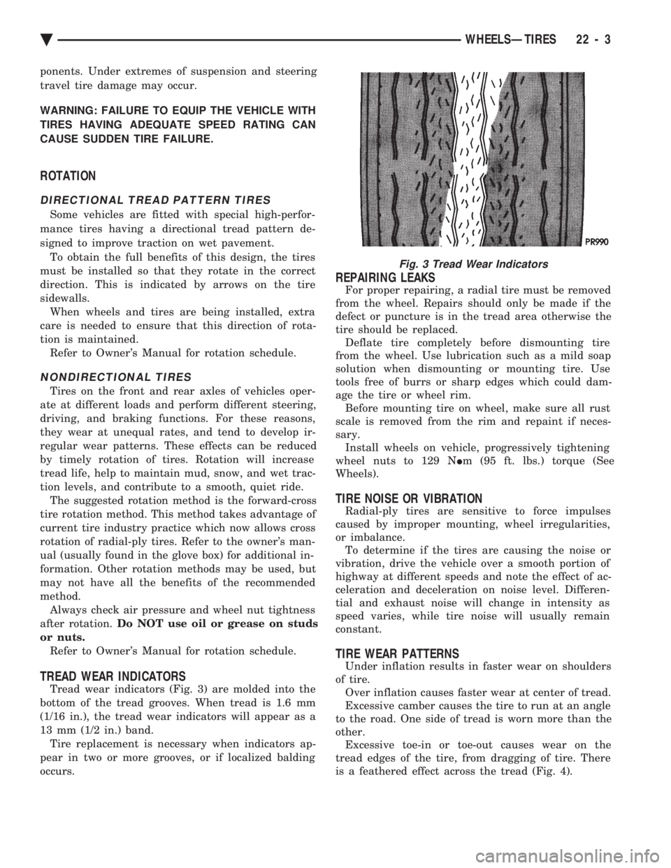
Tread wear indicators (Fig. 3) are molded into the
bottom of the tread grooves. When tread is 1.6 mm
(1/16 in.), the tread wear indicators will appear as a
13 mm (1/2 in.) band. Tire replacement is necessary when indicators ap-
pear in two or more grooves, or if localized balding
occurs.
REPAIRING LEAKS
For proper repairing, a radial tire must be removed
from the wheel. Repairs should only be made if the
defect or puncture is in the tread area otherwise the
tire should be replaced. Deflate tire completely before dismounting tire
from the wheel. Use lubrication such as a mild soap
solution when dismounting or mounting tire. Use
tools free of burrs or sharp edges which could dam-
age the tire or wheel rim. Before mounting tire on wheel, make sure all rust
scale is removed from the rim and repaint if neces-
sary. Install wheels on vehicle, progressively tightening
wheel nuts to 129 N Im (95 ft. lbs.) torque (See
Wheels).
TIRE NOISE OR VIBRATION
Radial-ply tires are sensitive to force impulses
caused by improper mounting, wheel irregularities,
or imbalance. To determine if the tires are causing the noise or
vibration, drive the vehicle over a smooth portion of
highway at different speeds and note the effect of ac-
celeration and deceleration on noise level. Differen-
tial and exhaust noise will change in intensity as
speed varies, while tire noise will usually remain
constant.
TIRE WEAR PATTERNS
Under inflation results in faster wear on shoulders
of tire. Over inflation causes faster wear at center of tread.
Excessive camber causes the tire to run at an angle
to the road. One side of tread is worn more than the
other. Excessive toe-in or toe-out causes wear on the
tread edges of the tire, from dragging of tire. There
is a feathered effect across the tread (Fig. 4).
Fig. 3 Tread Wear Indicators
Ä WHEELSÐTIRES 22 - 3