checking oil CHEVROLET DYNASTY 1993 Owner's Manual
[x] Cancel search | Manufacturer: CHEVROLET, Model Year: 1993, Model line: DYNASTY, Model: CHEVROLET DYNASTY 1993Pages: 2438, PDF Size: 74.98 MB
Page 553 of 2438
(5) Reconnect battery.
GAUGES
CAUTION: During the removal and installation
watch overlays are not damage.
It is not necessary to remove instrument cluster
from vehicle for gauge replacement. When removing gauge assemblies from cluster,
gauge must be pulled straight out, not twisted, or
damage to gauge pins may result.
MULTIPLE GAUGE INOPERATIVE
Volt, speedometer, tachometer and other gauges
appear to malfunction. Also check warning indicator
lamps: (1) Remove cluster
(2) Check for ignition voltage at pin E of the red
connector. If no voltage, repair as necessary (Fig. 8). (3) Check for ground continuity between pin C of
the gray connector. If no ground, repair as necessary. (4) If voltage and ground OK and pins or connec-
tors are not distorted, replace printed circuit board. (5) Install cluster.
SINGLE GAUGE INOPERATIVE (FIG. 9 AND10)
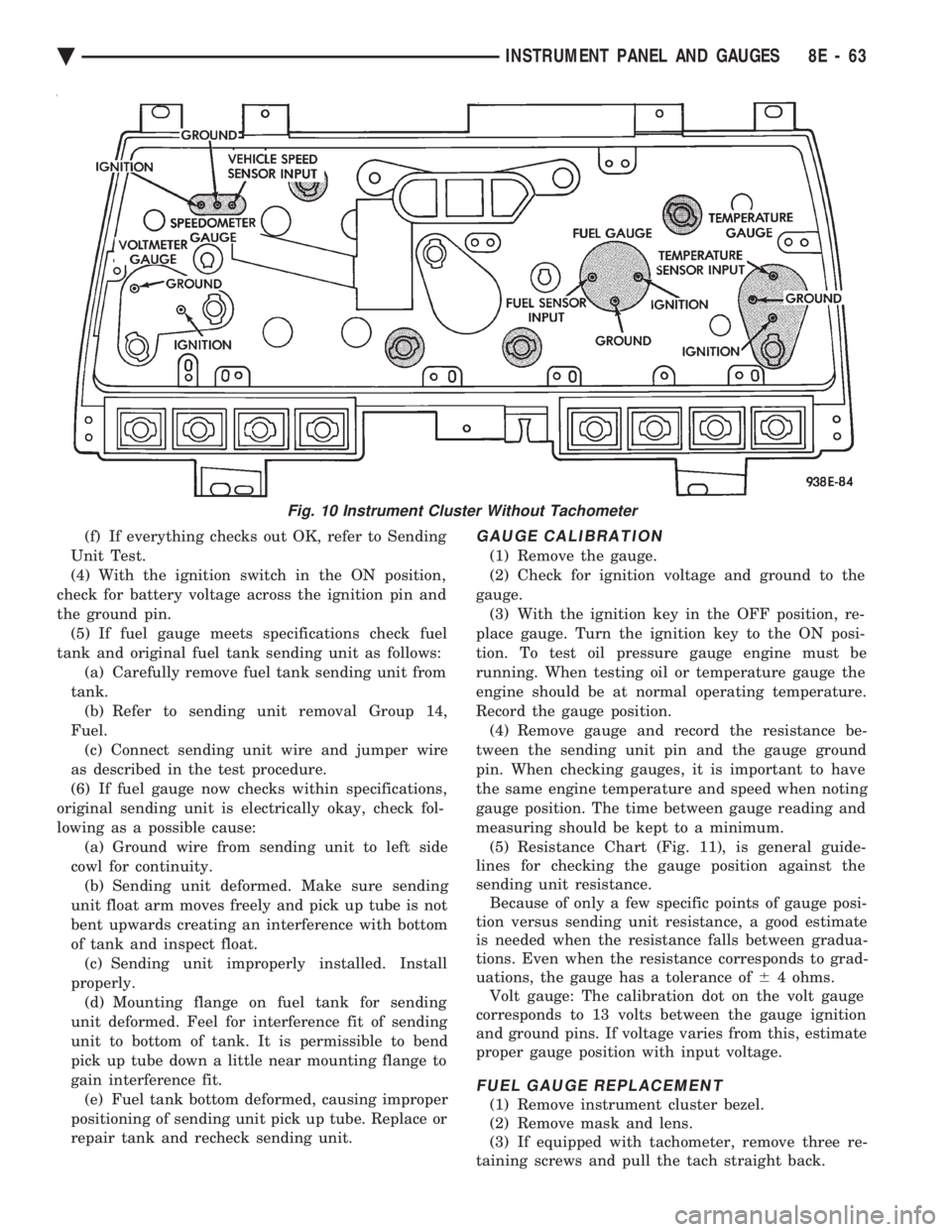
(1) Remove gauge in question. (2) With the ignition key ON, check for ignition
voltage at ignition pin of gauge. Check for ground at
ground pin of gauge. (a) If no voltage or ground, remove cluster and
check pin E red connector for ignition voltage or
pin C gray connector for ground (Fig. 8). (b) If no voltage or ground, repair as necessary.
Refer to 8W, Wiring Diagrams. (c) If there is voltage or ground, check cluster for
distorted terminals. If terminals are OK, replace
printed circuit board.
(3) When testing the temperature gauge, allow the
engine to run until the vehicle reaches a normal op-
erating temperature. Turn ignition OFF and remove
gauge from cluster.
² When checking the temperature and oil pressure
gauges, it is important to have the same engine tem-
perature and engine speed when noting gauge posi-
tion.
² The time between gauge position reading and
sending unit measuring should be kept to a mini-
mum.
² When testing oil pressure gauge, engine needs to
be running. (a) Measure and record the resistance between
sending unit pin and ground pin of the gauge in
question. Refer to Gauge Calibration.
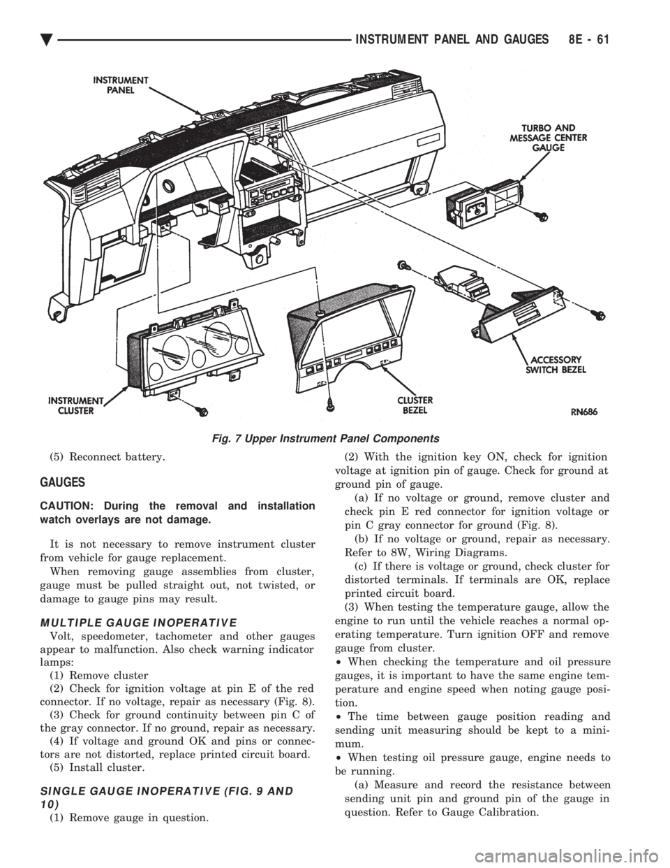
Fig. 7 Upper Instrument Panel Components
Ä INSTRUMENT PANEL AND GAUGES 8E - 61
Page 555 of 2438
(f) If everything checks out OK, refer to Sending
Unit Test.
(4) With the ignition switch in the ON position,
check for battery voltage across the ignition pin and
the ground pin. (5) If fuel gauge meets specifications check fuel
tank and original fuel tank sending unit as follows: (a) Carefully remove fuel tank sending unit from
tank. (b) Refer to sending unit removal Group 14,
Fuel. (c) Connect sending unit wire and jumper wire
as described in the test procedure.
(6) If fuel gauge now checks within specifications,
original sending unit is electrically okay, check fol-
lowing as a possible cause: (a) Ground wire from sending unit to left side
cowl for continuity. (b) Sending unit deformed. Make sure sending
unit float arm moves freely and pick up tube is not
bent upwards creating an interference with bottom
of tank and inspect float. (c) Sending unit improperly installed. Install
properly. (d) Mounting flange on fuel tank for sending
unit deformed. Feel for interference fit of sending
unit to bottom of tank. It is permissible to bend
pick up tube down a little near mounting flange to
gain interference fit. (e) Fuel tank bottom deformed, causing improper
positioning of sending unit pick up tube. Replace or
repair tank and recheck sending unit.GAUGE CALIBRATION
(1) Remove the gauge.
(2) Check for ignition voltage and ground to the
gauge. (3) With the ignition key in the OFF position, re-
place gauge. Turn the ignition key to the ON posi-
tion. To test oil pressure gauge engine must be
running. When testing oil or temperature gauge the
engine should be at normal operating temperature.
Record the gauge position. (4) Remove gauge and record the resistance be-
tween the sending unit pin and the gauge ground
pin. When checking gauges, it is important to have
the same engine temperature and speed when noting
gauge position. The time between gauge reading and
measuring should be kept to a minimum. (5) Resistance Chart (Fig. 11), is general guide-
lines for checking the gauge position against the
sending unit resistance. Because of only a few specific points of gauge posi-
tion versus sending unit resistance, a good estimate
is needed when the resistance falls between gradua-
tions. Even when the resistance corresponds to grad-
uations, the gauge has a tolerance of 64 ohms.
Volt gauge: The calibration dot on the volt gauge
corresponds to 13 volts between the gauge ignition
and ground pins. If voltage varies from this, estimate
proper gauge position with input voltage.
FUEL GAUGE REPLACEMENT
(1) Remove instrument cluster bezel.
(2) Remove mask and lens.
(3) If equipped with tachometer, remove three re-
taining screws and pull the tach straight back.
Fig. 10 Instrument Cluster Without Tachometer
Ä INSTRUMENT PANEL AND GAUGES 8E - 63
Page 1569 of 2438
scuffing, scoring or scratches. Usually a few strokes
will clean up a bore and maintain the required limits.(2) Deglazing of the cylinder walls may be done
using a cylinder surfacing hone, Tool C-3501, equipped
with 280 grit stones (C-3501-3810) if the cylinder bore
is straight and round. 20-60 strokes depending on the
bore condition will be sufficient to provide a satisfac-
tory surface. Inspect cylinder walls after each 20
strokes. Using a light honing oil available from major
oil distributors. Do not use engine or transmission
oil, mineral spirits or kerosene. (3) Honing should be done by moving the hone up
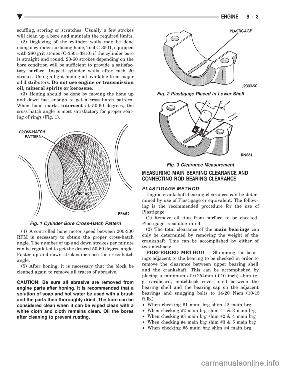
and down fast enough to get a cross-hatch pattern.
When hone marks intersectat 50-60 degrees, the
cross hatch angle is most satisfactory for proper seat-
ing of rings (Fig. 1).
(4) A controlled hone motor speed between 200-300
RPM is necessary to obtain the proper cross-hatch
angle. The number of up and down strokes per minute
can be regulated to get the desired 50-60 degree angle.
Faster up and down strokes increase the cross-hatch
angle. (5) After honing, it is necessary that the block be
cleaned again to remove all traces of abrasive.
CAUTION: Be sure all abrasive are removed from
engine parts after honing. It is recommended that a
solution of soap and hot water be used with a brush
and the parts then thoroughly dried. The bore can be
considered clean when it can be wiped clean with a
white cloth and cloth remains clean. Oil the bores
after cleaning to prevent rusting.
MEASURING MAIN BEARING CLEARANCE AND
CONNECTING ROD BEARING CLEARANCE
PLASTIGAGE METHOD
Engine crankshaft bearing clearances can be deter-
mined by use of Plastigage or equivalent. The follow-
ing is the recommended procedure for the use of
Plastigage: (1) Remove oil film from surface to be checked.
Plastigage is soluble in oil. (2) The total clearance of the main bearingscan
only be determined by removing the weight of the
crankshaft. This can be accomplished by either of
two methods: PREFERRED METHOD Ð Shimming the bear-
ings adjacent to the bearing to be checked in order to
remove the clearance between upper bearing shell
and the crankshaft. This can be accomplished by
placing a minimum of 0.254mm (.010 inch) shim (e.
g. cardboard, matchbook cover, etc.) between the
bearing shell and the bearing cap on the adjacent
bearings and snugging bolts to 14-20 N Im (10-15
ft.lb.)
² When checking #1 main brg shim #2 main brg
²
When checking #2 main brg shim # 1 & 3 main brg
²When checking #3 main brg shim #2 & 4 main brg
²When checking #4 main brg shim #3 & 5 main brg
²When checking #5 main brg shim #4 main brg
Fig. 2 Plastigage Placed in Lower Shell
Fig. 3 Clearance Measurement
Fig. 1 Cylinder Bore Cross-Hatch Pattern
Ä ENGINE 9 - 3
Page 1570 of 2438
REMOVE ALL SHIMS BEFORE REASSEM-
BLING ENGINE ALTERNATIVE METHOD Ð With the weight of
the crankshaft being supported by a jack under the
counterweight adjacent to the bearing being checked. (3) Place a piece of Plastigage across the entire
width of the bearing shell in the cap approximately
6.35 mm (1/4 inch) off center and away from the oil
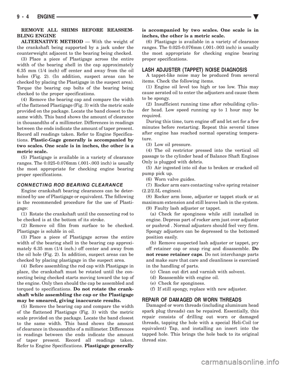
holes (Fig. 2). (In addition, suspect areas can be
checked by placing the Plastigage in the suspect area).
Torque the bearing cap bolts of the bearing being
checked to the proper specifications. (4) Remove the bearing cap and compare the width
of the flattened Plastigage (Fig. 3) with the metric scale
provided on the package. Locate the band closest to the
same width. This band shows the amount of clearance
in thousandths of a millimeter. Differences in readings
between the ends indicate the amount of taper present.
Record all readings taken. Refer to Engine Specifica-
tions. Plastic-Gage generally is accompanied by
two scales. One scale is in inches, the other is a
metric scale. (5) Plastigage is available in a variety of clearance
ranges. The 0.025-0.076mm (.001-.003 inch) is usually
the most appropriate for checking engine bearing
proper specifications.
CONNECTING ROD BEARING CLEARANCE
Engine crankshaft bearing clearances can be deter-
mined by use of Plastigage or equivalent. The following
is the recommended procedure for the use of Plasti-
gage: (1) Rotate the crankshaft until the connecting rod to
be checked is at the bottom of its stroke. (2) Remove oil film from surface to be checked.
Plastigage is soluble in oil. (3) Place a piece of Plastigage across the entire
width of the bearing shell in the bearing cap approxi-
mately 6.35 mm (1/4 inch.) off center and away from
the oil hole (Fig. 2). In addition, suspect areas can be
checked by placing plastigage in the suspect area. (4) Before assembling the rod cap with Plastigage in
place, the crankshaft must be rotated until the con-
necting being checked starts moving toward the top of
the engine. Only then should the cap be assembled and
torqued to specifications. Do not rotate the crank-
shaft while assembling the cap or the Plastigage
may be smeared, giving inaccurate results. (5) Remove the bearing cap and compare the width
of the flattened Plastigage (Fig. 3) with the metric
scale provided on the package. Locate the band closest
to the same width. This band shows the amount
of clearance in thousandths of a millimeter. Differences
in readings between the ends indicate the amount
of taper present. Record all readings taken.
Refer to Engine Specifications. Plastigage generally is accompanied by two scales. One scale is in
inches, the other is a metric scale. (6) Plastigage is available in a variety of clearance
ranges. The 0.025-0.076mm (.001-.003 inch) is usually
the most appropriate for checking engine bearing
proper specifications.
LASH ADJUSTER (TAPPET) NOISE DIAGNOSIS
A tappet-like noise may be produced from several
items. Check the following items. (1) Engine oil level too high or too low. This may
cause aerated oil to enter the adjusters and cause them
to be spongy. (2) Insufficient running time after rebuilding cylin-
der head. Low speed running up to 1 hour may be
required. During this time, turn engine off and let set for a few
minutes before restarting. Repeat this several times
after engine has reached normal operating tempera-
ture. (3) Low oil pressure.
(4) The oil restrictor pressed into the vertical oil
passage to the cylinder head of Balance Shaft Engines
Only is plugged with debris. (5) Air ingested into oil due to broken or cracked oil
pump pick up. (6) Worn valve guides.
(7) Rocker arm ears contacting valve spring retainer
(2.2/2.5L engines). (8) Rocker arm loose, adjuster or tappet stuck or at
maximum extension and still leaves lash in the system. (9) Faulty lash adjuster or tappet.(a) Check for sponginess while still installed in
engine. Depress part of rocker arm just over adjuster
or pushrod . Normal adjusters should feel very firm.
Spongy adjusters can be depressed to the bottomed
position easily. (b) Remove suspected lash adjuster or tappet, pry
off retainer cap or snap ring and disassemble. Do
not reuse retainer caps . Do not interchange parts
and make sure that care and cleanliness is exercised
in the handling of parts. (c) Clean out dirt and varnish with solvent.
(d) Reassemble with engine oil.
(e) Check for sponginess.
(f) If still spongy, replace with new adjuster.
REPAIR OF DAMAGED OR WORN THREADS
Damaged or worn threads (including aluminum head
spark plug threads) can be repaired. Essentially, this
repair consists of drilling out worn or damaged
threads, tapping the hole with a special Heli-Coil (or
equivalent) Tap, and installing an insert into the
tapped hole. This brings the hole back to its original
thread size.
9 - 4 ENGINE Ä
Page 1574 of 2438
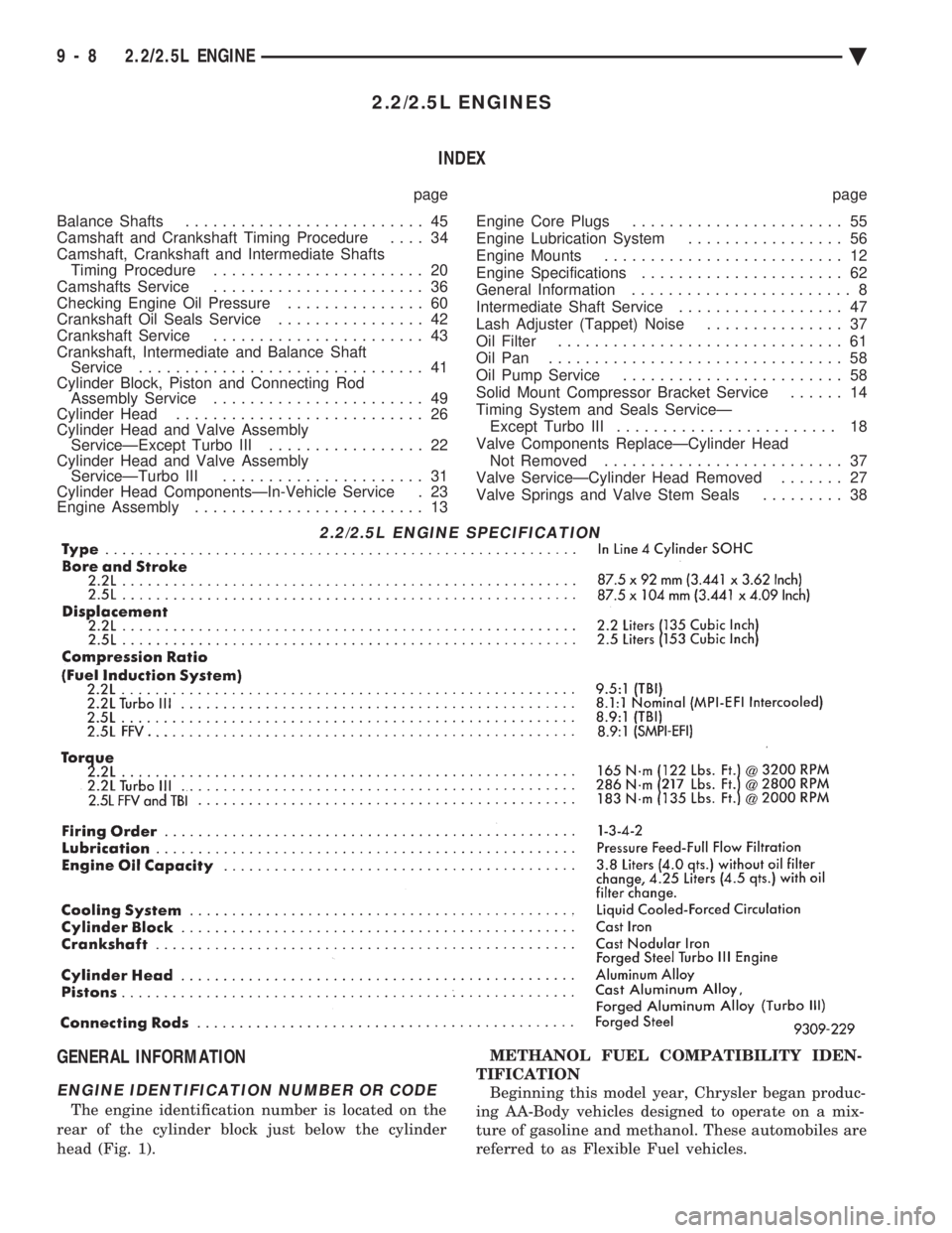
2.2/2.5L ENGINES INDEX
page page
Balance Shafts .......................... 45
Camshaft and Crankshaft Timing Procedure .... 34
Camshaft, Crankshaft and Intermediate Shafts Timing Procedure ....................... 20
Camshafts Service ....................... 36
Checking Engine Oil Pressure ............... 60
Crankshaft Oil Seals Service ................ 42
Crankshaft Service ....................... 43
Crankshaft, Intermediate and Balance Shaft Service ............................... 41
Cylinder Block, Piston and Connecting Rod Assembly Service ....................... 49
Cylinder Head ........................... 26
Cylinder Head and Valve Assembly ServiceÐExcept Turbo III ................. 22
Cylinder Head and Valve Assembly ServiceÐTurbo III ...................... 31
Cylinder Head ComponentsÐIn-Vehicle Service . 23
Engine Assembly ......................... 13 Engine Core Plugs
....................... 55
Engine Lubrication System ................. 56
Engine Mounts .......................... 12
Engine Specifications ...................... 62
General Information ........................ 8
Intermediate Shaft Service .................. 47
Lash Adjuster (Tappet) Noise ............... 37
Oil Filter ............................... 61
Oil Pan ................................ 58
Oil Pump Service ........................ 58
Solid Mount Compressor Bracket Service ...... 14
Timing System and Seals ServiceÐ Except Turbo III ........................ 18
Valve Components ReplaceÐCylinder Head Not Removed .......................... 37
Valve ServiceÐCylinder Head Removed ....... 27
Valve Springs and Valve Stem Seals ......... 38
GENERAL INFORMATION
ENGINE IDENTIFICATION NUMBER OR CODE
The engine identification number is located on the
rear of the cylinder block just below the cylinder
head (Fig. 1). METHANOL FUEL COMPATIBILITY IDEN-
TIFICATION Beginning this model year, Chrysler began produc-
ing AA-Body vehicles designed to operate on a mix-
ture of gasoline and methanol. These automobiles are
referred to as Flexible Fuel vehicles.
2.2/2.5L ENGINE SPECIFICATION
9 - 8 2.2/2.5L ENGINE Ä
Page 1593 of 2438
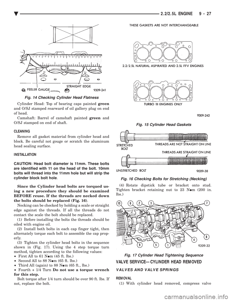
Cylinder Head: Top of bearing caps painted green
and O/SJ stamped rearward of oil gallery plug on end
of head. Camshaft: Barrel of camshaft painted greenand
O/SJ stamped on end of shaft.
CLEANING
Remove all gasket material from cylinder head and
block. Be careful not gouge or scratch the aluminum
head sealing surface.
INSTALLATION
CAUTION: Head bolt diameter is 11mm. These bolts
are identified with 11 on the head of the bolt. 10mm
bolts will thread into the 11mm hole but will strip the
cylinder block bolt hole .
Since the Cylinder head bolts are torqued us-
ing a new procedure they should be examined
BEFORE reuse. If the threads are necked down
the bolts should be replaced (Fig. 16) .
Necking can be checked by holding a scale or straight
edge against the threads. If all the threads do not
contact the scale the bolt should be replaced. (1) Before installing the bolts the threads should be
oiled with engine oil. (2) Install both bolts in each cap finger tight, then
alternately torque each bolt to assemble the cap prop-
erly. (3) Tighten the cylinder head bolts in the sequence
shown in (Fig. 17). Using the 4 step torque turn
method, tighten according to the following values:
² First All to 61 N Im (45 ft. lbs.)
² Second All to 88 N Im (65 ft. lbs.)
² Third All (again) to 88 N Im (65 ft., lbs.)
² Fourth + 1/4 Turn Do not use a torque wrench
for this step. Bolt torque after 1/4 turn should be over 90 ft. lbs. If
not, replace the bolt. (4) Rotate dipstick tube or bracket onto stud.
Tighten bracket retaining nut to 23 N Im (200 in.
lbs.)
VALVE SERVICEÐCYLINDER HEAD REMOVED
VALVES AND VALVE SPRINGS
REMOVAL
(1) With cylinder head removed, compress valve
Fig. 15 Cylinder Head Gaskets
Fig. 16 Checking Bolts for Stretching (Necking)
Fig. 17 Cylinder Head Tightening Sequence
Fig. 14 Checking Cylinder Head Flatness
Ä 2.2/2.5L ENGINE 9 - 27
Page 1596 of 2438
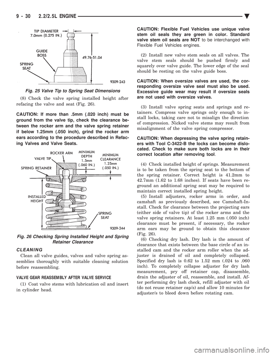
(8) Check the valve spring installed height after
refacing the valve and seat (Fig. 26).
CAUTION: If more than .5mm (.020 inch) must be
ground from the valve tip, check the clearance be-
tween the rocker arm and the valve spring retainer
if below 1.25mm (.050 inch), grind the rocker arm
ears according to the procedure described in Refac-
ing Valves and Valve Seats.
CLEANING
Clean all valve guides, valves and valve spring as-
semblies thoroughly with suitable cleaning solution
before reassembling.
VALVE GEAR REASSEMBLY AFTER VALVE SERVICE (1) Coat valve stems with lubrication oil and insert
in cylinder head. CAUTION: Flexible Fuel Vehicles use unique valve
stem oil seals they are green in color. Standard
valve stem oil seals are NOT to be interchanged with
Flexible Fuel Vehicles engines.
(2) Install new valve stem seals on all valves. The
valve stem seals should be pushed firmly and
squarely over valve guide. The lower edge of the seal
should be resting on the valve guide boss.
CAUTION: When oversize valves are used, the cor-
responding oversize valve seal must also be used.
Excessive guide wear may result if oversize seals
are not used with oversize valves.
(3) Install valve spring seats and springs and re-
tainers. Compress valve springs only enough to in-
stall locks, taking care not to misalign the direction
of compression. Nicked valve stems may result from
misalignment of the valve spring compressor.
CAUTION: When depressing the valve spring retain-
ers with Tool C-3422-B the locks can become dislo-
cated. Check to make sure both locks are in their
correct location after removing tool .
(4) Check installed height of springs. Measurement
is to be taken from the spring seat to the bottom of
the spring retainer. Correct height is 41.2mm to
42.7mm (1.62 to 1.68 inches). If seats have been re-
ground an additional spring seat may be required to
maintain correct installed spring height. (5) Install adjusters, rocker arms in order, and
camshaft as previously described, see Camshaft-In-
stall. Check for clearance between the projecting ears
(either side of valve tip) of the rocker arms and the
valve spring retainers. At least 1.25 mm (.050 inch)
clearance must be present, if necessary, the rocker
arm ears may be ground to obtain this clearance
(Fig. 26). (6) Checking dry lash. Dry lash is the amount of
clearance that exists between the base circle of an in-
stalled cam and the rocker arm roller when the ad-
juster is drained of oil and completely collapsed.
Specified dry lash is 0.62 to 1.52 mm (.024 to .060
inch). To completely collapse adjuster for dry lash
measurement, pry off retainer cap, disassemble,
drain the adjuster of oil, reassemble, and install. Af-
ter performing dry lash check, refill adjuster with oil
(do not reuse retainer cap/s) and allow 10 minutes for
adjuster/s to bleed down before rotating cam.
Fig. 25 Valve Tip to Spring Seat Dimensions
Fig. 26 Checking Spring Installed Height and Spring Retainer Clearance
9 - 30 2.2/2.5L ENGINE Ä
Page 1597 of 2438
CYLINDER HEAD AND VALVE ASSEMBLY
SERVICEÐTURBO III
CYLINDER HEAD COVER SEALING
(1) Before installation, clean cylinder head and cover
mating surfaces. Make certain rails are flat.
Caution: Do not allow oil or solvents to contact the
timing belt as they can deteriorate the rubber and
cause tooth skipping.
(2) Install covers and gasket assembly to head and
torque to 12 N Im (105 in.lbs.).
CYLINDER HEAD
REMOVAL
Refer to Intake and Exhaust Manifold Service in
Exhaust Systems and Intake Manifold Group 11 for
removal procedure for the intake and exhaust mani-
folds. (1) The Timing Belt and Solid Mount Compressor
Mount Bracket must be removed before the cylinder
head can be removed. Refer to procedure outlined in
this group for service procedures. (2) Remove cylinder head bolts.
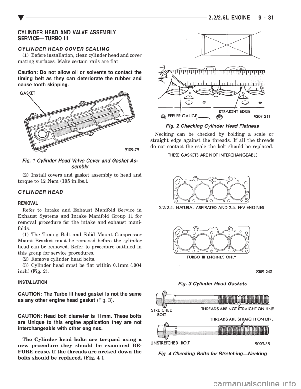
(3) Cylinder head must be flat within 0.1mm (.004
inch) (Fig. 2).
INSTALLATION
CAUTION: The Turbo III head gasket is not the same
as any other engine head gasket (Fig. 3).
CAUTION: Head bolt diameter is 11mm. These bolts
are Unique to this engine application they are not
interchangeable with other engines.
The Cylinder head bolts are torqued using a
new procedure they should be examined BE-
FORE reuse. If the threads are necked down the
bolts should be replaced. (Fig. 4 ). Necking can be checked by holding a scale or
straight edge against the threads. If all the threads
do not contact the scale the bolt should be replaced.
Fig. 2 Checking Cylinder Head Flatness
Fig. 3 Cylinder Head Gaskets
Fig. 4 Checking Bolts for StretchingÐNecking
Fig. 1 Cylinder Head Valve Cover and Gasket As- sembly
Ä 2.2/2.5L ENGINE 9 - 31
Page 1603 of 2438
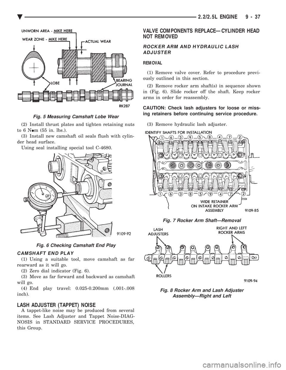
(2) Install thrust plates and tighten retaining nuts
to6N Im (55 in. lbs.).
(3) Install new camshaft oil seals flush with cylin-
der head surface. Using seal installing special tool C-4680.
CAMSHAFT END PLAY
(1) Using a suitable tool, move camshaft as far
rearward as it will go. (2) Zero dial indicator (Fig. 6).
(3) Move as far forward and backward as camshaft
will go. (4) End play travel: 0.025-0.200mm (.001-.008
inch).
LASH ADJUSTER (TAPPET) NOISE
A tappet-like noise may be produced from several
items. See Lash Adjuster and Tappet Noise-DIAG-
NOSIS in STANDARD SERVICE PROCEDURES,
this Group.
VALVE COMPONENTS REPLACEÐCYLINDER HEAD
NOT REMOVED
ROCKER ARM AND HYDRAULIC LASH
ADJUSTER
REMOVAL
(1) Remove valve cover. Refer to procedure previ-
ously outlined in this section.
(2) Remove rocker arm shaft(s) in sequence shown
in (Fig. 6). Slide rocker off the shaft. Keep rocker
arms in order for reassembly.
CAUTION: Check lash adjusters for loose or miss-
ing retainers before continuing service procedure.
(3) Remove hydraulic lash adjuster.
Fig. 5 Measuring Camshaft Lobe Wear
Fig. 6 Checking Camshaft End Play
Fig. 7 Rocker Arm ShaftÐRemoval
Fig. 8 Rocker Arm and Lash Adjuster AssemblyÐRight and Left
Ä 2.2/2.5L ENGINE 9 - 37
Page 1606 of 2438
VALVE GEAR REASSEMBLY AFTER VALVE SERVICE
(1) Coat valve stems with lubrication oil and insert
in cylinder head. (2) Install new valve stem seals on all valves. The
valve stem seals should be pushed firmly and
squarely over valve guide. The lower edge of the seal
should be resting on the valve guide boss. (3) Install valve spring seats and springs and re-
tainers. Compress valve springs only enough to in-
stall locks, taking care not to misalign the direction
of compression. Nicked valve stems may result from
misalignment of the valve spring compressor.
CAUTION: When depressing the valve spring retain-
ers with Valve Spring Compressor Tool C-3422-B
with adopters 6537 and 6526 (Fig. 11) the locks can
become dislocated. Check to make sure both locks
are in their correct location after removing tool.
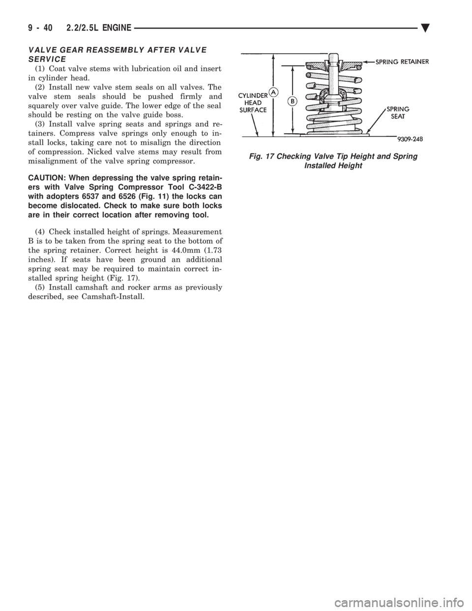
(4) Check installed height of springs. Measurement
B is to be taken from the spring seat to the bottom of
the spring retainer. Correct height is 44.0mm (1.73
inches). If seats have been ground an additional
spring seat may be required to maintain correct in-
stalled spring height (Fig. 17). (5) Install camshaft and rocker arms as previously
described, see Camshaft-Install.
Fig. 17 Checking Valve Tip Height and Spring Installed Height
9 - 40 2.2/2.5L ENGINE Ä