checking oil CHEVROLET DYNASTY 1993 Owner's Guide
[x] Cancel search | Manufacturer: CHEVROLET, Model Year: 1993, Model line: DYNASTY, Model: CHEVROLET DYNASTY 1993Pages: 2438, PDF Size: 74.98 MB
Page 1609 of 2438
CRANKSHAFT SERVICE
CRANKSHAFT MAIN BEARINGS
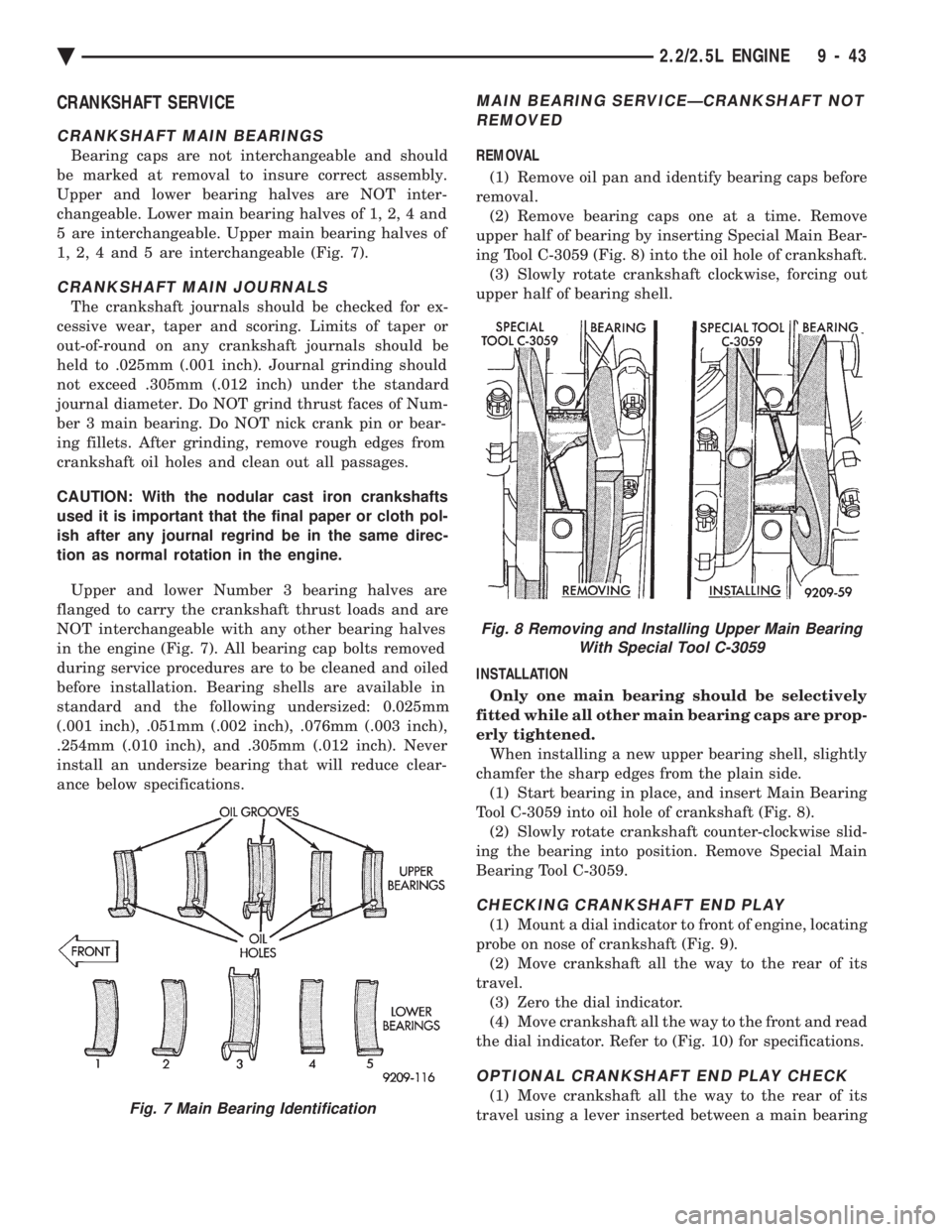
Bearing caps are not interchangeable and should
be marked at removal to insure correct assembly.
Upper and lower bearing halves are NOT inter-
changeable. Lower main bearing halves of 1, 2, 4 and
5 are interchangeable. Upper main bearing halves of
1, 2, 4 and 5 are interchangeable (Fig. 7).
CRANKSHAFT MAIN JOURNALS
The crankshaft journals should be checked for ex-
cessive wear, taper and scoring. Limits of taper or
out-of-round on any crankshaft journals should be
held to .025mm (.001 inch). Journal grinding should
not exceed .305mm (.012 inch) under the standard
journal diameter. Do NOT grind thrust faces of Num-
ber 3 main bearing. Do NOT nick crank pin or bear-
ing fillets. After grinding, remove rough edges from
crankshaft oil holes and clean out all passages.
CAUTION: With the nodular cast iron crankshafts
used it is important that the final paper or cloth pol-
ish after any journal regrind be in the same direc-
tion as normal rotation in the engine.
Upper and lower Number 3 bearing halves are
flanged to carry the crankshaft thrust loads and are
NOT interchangeable with any other bearing halves
in the engine (Fig. 7). All bearing cap bolts removed
during service procedures are to be cleaned and oiled
before installation. Bearing shells are available in
standard and the following undersized: 0.025mm
(.001 inch), .051mm (.002 inch), .076mm (.003 inch),
.254mm (.010 inch), and .305mm (.012 inch). Never
install an undersize bearing that will reduce clear-
ance below specifications.
MAIN BEARING SERVICEÐCRANKSHAFT NOT REMOVED
REMOVAL
(1) Remove oil pan and identify bearing caps before
removal. (2) Remove bearing caps one at a time. Remove
upper half of bearing by inserting Special Main Bear-
ing Tool C-3059 (Fig. 8) into the oil hole of crankshaft. (3) Slowly rotate crankshaft clockwise, forcing out
upper half of bearing shell.
INSTALLATION Only one main bearing should be selectively
fitted while all other main bearing caps are prop-
erly tightened. When installing a new upper bearing shell, slightly
chamfer the sharp edges from the plain side. (1) Start bearing in place, and insert Main Bearing
Tool C-3059 into oil hole of crankshaft (Fig. 8). (2) Slowly rotate crankshaft counter-clockwise slid-
ing the bearing into position. Remove Special Main
Bearing Tool C-3059.
CHECKING CRANKSHAFT END PLAY
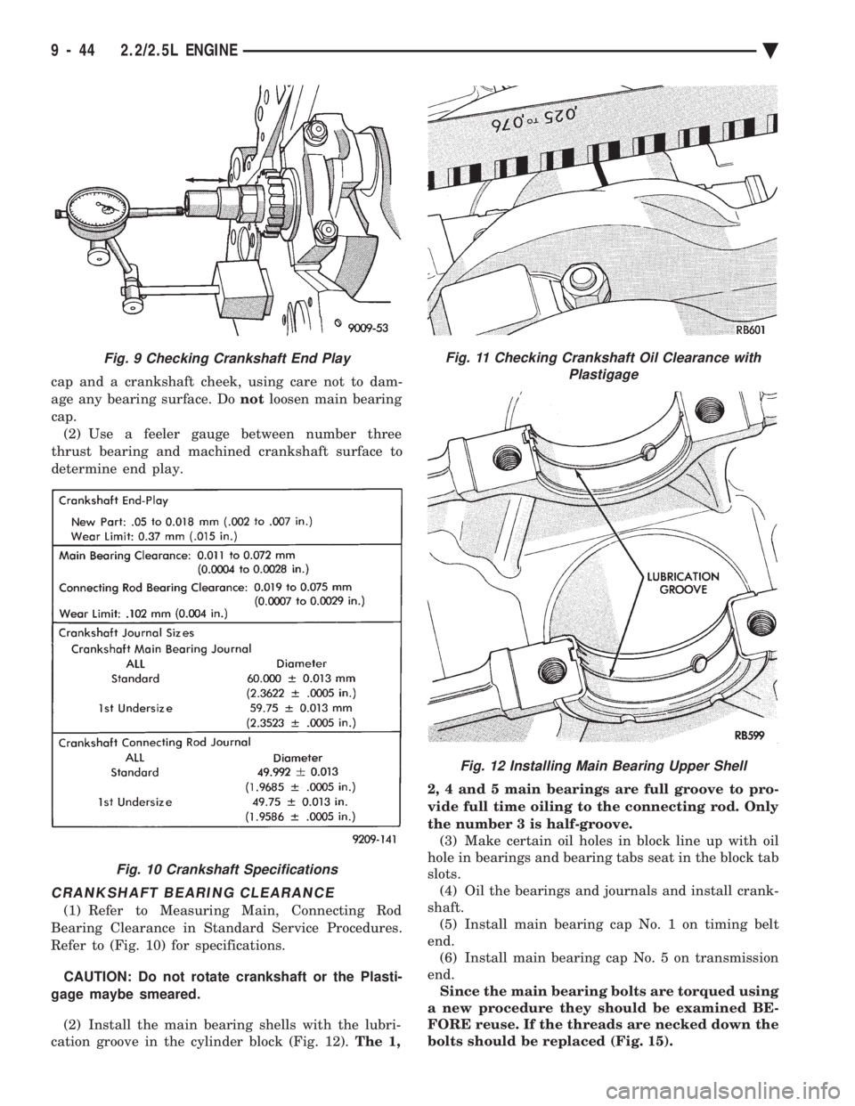
(1) Mount a dial indicator to front of engine, locating
probe on nose of crankshaft (Fig. 9). (2) Move crankshaft all the way to the rear of its
travel. (3) Zero the dial indicator.
(4) Move crankshaft all the way to the front and read
the dial indicator. Refer to (Fig. 10) for specifications.
OPTIONAL CRANKSHAFT END PLAY CHECK
(1) Move crankshaft all the way to the rear of its
travel using a lever inserted between a main bearingFig. 7 Main Bearing Identification
Fig. 8 Removing and Installing Upper Main Bearing With Special Tool C-3059
Ä 2.2/2.5L ENGINE 9 - 43
Page 1610 of 2438
cap and a crankshaft cheek, using care not to dam-
age any bearing surface. Do notloosen main bearing
cap. (2) Use a feeler gauge between number three
thrust bearing and machined crankshaft surface to
determine end play.
CRANKSHAFT BEARING CLEARANCE
(1) Refer to Measuring Main, Connecting Rod
Bearing Clearance in Standard Service Procedures.
Refer to (Fig. 10) for specifications.
CAUTION: Do not rotate crankshaft or the Plasti-
gage maybe smeared.
(2) Install the main bearing shells with the lubri-
cation groove in the cylinder block (Fig. 12). The 1, 2, 4 and 5 main bearings are full groove to pro-
vide full time oiling to the connecting rod. Only
the number 3 is half-groove.
(3) Make certain oil holes in block line up with oil
hole in bearings and bearing tabs seat in the block tab
slots. (4) Oil the bearings and journals and install crank-
shaft. (5) Install main bearing cap No. 1 on timing belt
end. (6) Install main bearing cap No. 5 on transmission
end. Since the main bearing bolts are torqued using
a new procedure they should be examined BE-
FORE reuse. If the threads are necked down the
bolts should be replaced (Fig. 15).
Fig. 9 Checking Crankshaft End Play
Fig. 10 Crankshaft Specifications
Fig. 11 Checking Crankshaft Oil Clearance with Plastigage
Fig. 12 Installing Main Bearing Upper Shell
9 - 44 2.2/2.5L ENGINE Ä
Page 1611 of 2438

Necking can be checked by holding a scale or straight
edge against the threads or by running a M11 x 1.50
nut the full length of the thread. If all the threads
do not contact the scale or if the nut does not run
down smoothly the bolt should be replaced. (7) Before installing the bolts the threads should be
oiled with engine oil. (8) Install both bolts in each cap finger tight, then
alternately torque each bolt to assemble the cap prop-
erly. (9) Tighten the bolts to 41 N Im plus 1/4 turn (30
ft.lbs. plus 1/4 turn). (Fig. 14)
BALANCE SHAFTS
2.2L Turbo III and 2.5L engines are equipped with
two counter rotating balance shafts installed in a
carrier attached to the lower crankcase (Fig. 1). The shafts are interconnected through gears. These
gears are driven by a short chain from the crank-
shaft, to rotate at two times crankshaft speed. This
counterbalances certain engine reciprocating forces.
REMOVAL
Refer to Engine Lubrication and Timing System
and Seals Service of this group for removal procedure
of necessary components to repair balance shafts.
(1) Remove chain cover, guide and tensioner (Fig.
16). Also see Carrier Assembly Removal for service
procedures requiring only temporary relocation of as-
sembly. (2) Remove balance shaft gear and chain sprocket
retaining screws and crankshaft chain sprocket torx
screws. Remove chain and sprocket assembly. (Fig.
17) (3) Remove gear cover retaining stud (double
ended to also retain chain guide). Remove cover and
balance shaft gears (Fig. 18). (4) Remove carrier rear cover and balance shafts.
(Fig. 19). (5) Remove six carrier to crankcase attaching bolts
to separate carrier (Fig. 1).
Fig. 16 Chain Cover, Guide and Tensioner
Fig. 13 Main Bearing Caps
Fig. 14 Installing Main Bearing Caps
Fig. 15 Checking Bolts For Stretching (Necked down)
Ä 2.2/2.5L ENGINE 9 - 45
Page 1616 of 2438

CYLINDER BLOCK CLEANING AND INSPECTION
(1) Clean cylinder block thoroughly and check all
core hole plugs for evidence of leaking. (2) If new core plugs are installed, Refer to Engine
Core Oil and Cam Plugs. (3) Examine block and cylinder bores for cracks or
fractures.
CYLINDER BORE INSPECTION
The cylinder walls should be checked for out-of-
round and taper with Tool C-119 (Fig. 5). The cylin-
der bore out-of-round is 0.050 mm (.002 inch)
maximum and cylinder bore taper is .125 mm (.005
inch) maximum. If the cylinder walls are badly
scuffed or scored, the cylinder block should be re-
bored and honed, and new pistons and rings fitted.
Whatever type of boring equipment is used, boring
and honing operation should be closely coordinated
with the fitting of pistons and rings in order that
specified clearances may be maintained. Refer to Honing Cylinder Bores outlined in the Standard
Service Procedures for specification and proce-
dures.
Measure the cylinder bore at three levels in direc-
tions A and B (Fig. 5). Top measurement should be
10mm ( 3/8 inch) down and bottom measurement
should be 10mm ( 3/8 inch.) up from bottom of bore.
Refer to (Fig. 6) for specifications.
SIZING PISTONS
Piston and cylinder wall must be clean and dry.
Piston diameter should be measured 90 degrees to
piston pin at size location shown in (Fig. 7). Cylinder
bores should be measured halfway down the cylinder
bore and transverse to the engine crankshaft center
line shown in (Fig. 5). Refer to (Fig. 6) for specifica-
Fig. 5 Checking Cylinder Bore Size
Fig. 6 Piston Size Location and Clearance Chart
Fig. 4 Connecting Rod Protectors
9 - 50 2.2/2.5L ENGINE Ä
Page 1620 of 2438
firmly and press down the portion to be installed un-
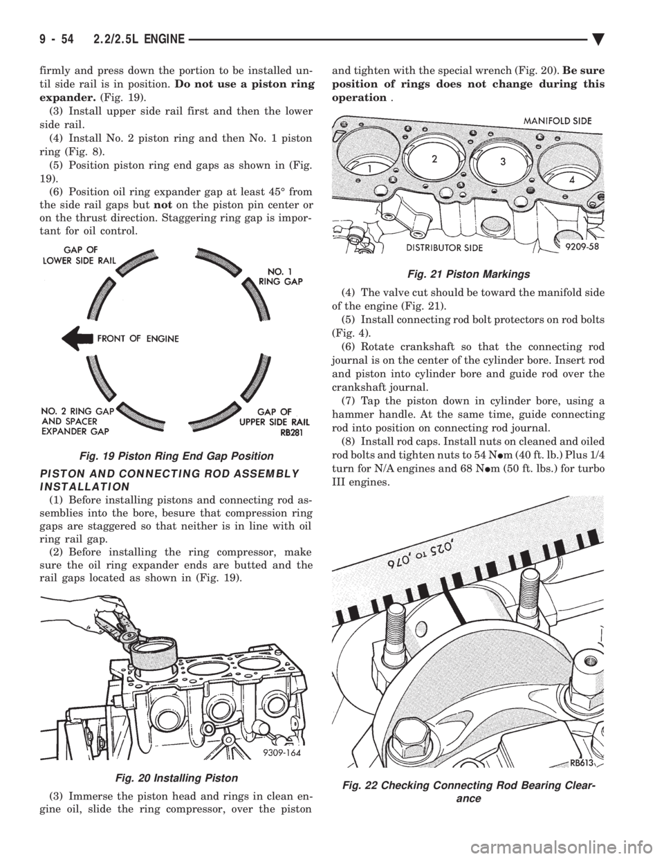
til side rail is in position. Do not use a piston ring
expander. (Fig. 19).
(3) Install upper side rail first and then the lower
side rail. (4) Install No. 2 piston ring and then No. 1 piston
ring (Fig. 8). (5) Position piston ring end gaps as shown in (Fig.
19). (6) Position oil ring expander gap at least 45É from
the side rail gaps but noton the piston pin center or
on the thrust direction. Staggering ring gap is impor-
tant for oil control.
PISTON AND CONNECTING ROD ASSEMBLY INSTALLATION
(1) Before installing pistons and connecting rod as-
semblies into the bore, besure that compression ring
gaps are staggered so that neither is in line with oil
ring rail gap. (2) Before installing the ring compressor, make
sure the oil ring expander ends are butted and the
rail gaps located as shown in (Fig. 19).
(3) Immerse the piston head and rings in clean en-
gine oil, slide the ring compressor, over the piston and tighten with the special wrench (Fig. 20).
Be sure
position of rings does not change during this
operation .
(4) The valve cut should be toward the manifold side
of the engine (Fig. 21). (5) Install connecting rod bolt protectors on rod bolts
(Fig. 4). (6) Rotate crankshaft so that the connecting rod
journal is on the center of the cylinder bore. Insert rod
and piston into cylinder bore and guide rod over the
crankshaft journal. (7) Tap the piston down in cylinder bore, using a
hammer handle. At the same time, guide connecting
rod into position on connecting rod journal. (8) Install rod caps. Install nuts on cleaned and oiled
rod bolts and tighten nuts to 54 N Im (40 ft. lb.) Plus 1/4
turn for N/A engines and 68 N Im (50 ft. lbs.) for turbo
III engines.
Fig. 19 Piston Ring End Gap Position
Fig. 20 Installing Piston
Fig. 21 Piston Markings
Fig. 22 Checking Connecting Rod Bearing Clear- ance
9 - 54 2.2/2.5L ENGINE Ä
Page 1621 of 2438
CONNECTING RODS
(1) Follow procedure specified in the Standard Ser-
vice Procedures Section for Measuring Main Bearing
Clearance and Connecting Rod Bearing Clearance
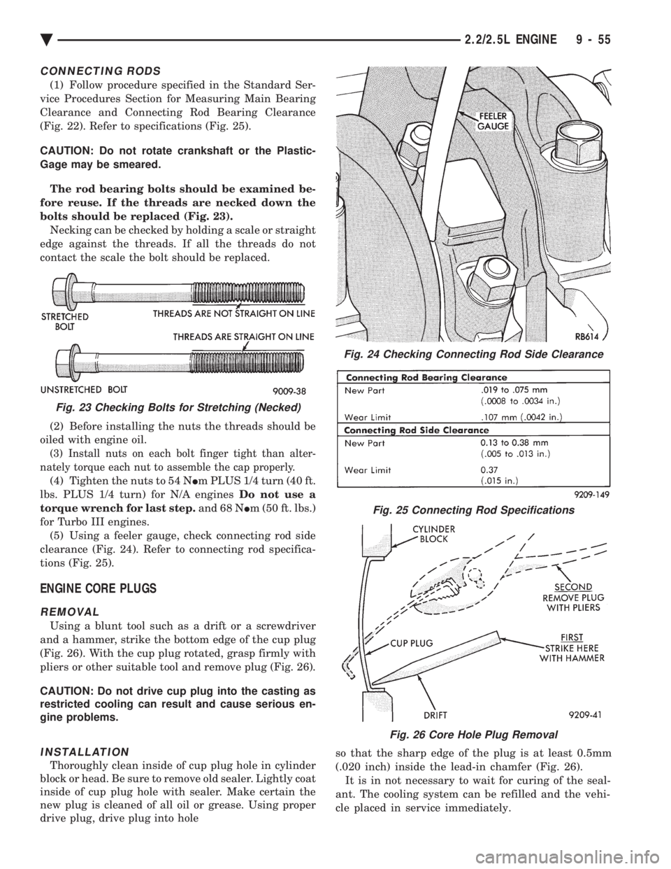
(Fig. 22). Refer to specifications (Fig. 25).
CAUTION: Do not rotate crankshaft or the Plastic-
Gage may be smeared.
The rod bearing bolts should be examined be-
fore reuse. If the threads are necked down the
bolts should be replaced (Fig. 23). Necking can be checked by holding a scale or straight
edge against the threads. If all the threads do not
contact the scale the bolt should be replaced.
(2) Before installing the nuts the threads should be
oiled with engine oil.
(3) Install nuts on each bolt finger tight than alter-
nately torque each nut to assemble the cap properly.
(4) Tighten the nuts to 54 N Im PLUS 1/4 turn (40 ft.
lbs. PLUS 1/4 turn) for N/A engines Do not use a
torque wrench for last step. and 68 NIm (50 ft. lbs.)
for Turbo III engines. (5) Using a feeler gauge, check connecting rod side
clearance (Fig. 24). Refer to connecting rod specifica-
tions (Fig. 25).
ENGINE CORE PLUGS
REMOVAL
Using a blunt tool such as a drift or a screwdriver
and a hammer, strike the bottom edge of the cup plug
(Fig. 26). With the cup plug rotated, grasp firmly with
pliers or other suitable tool and remove plug (Fig. 26).
CAUTION: Do not drive cup plug into the casting as
restricted cooling can result and cause serious en-
gine problems.
INSTALLATION
Thoroughly clean inside of cup plug hole in cylinder
block or head. Be sure to remove old sealer. Lightly coat
inside of cup plug hole with sealer. Make certain the
new plug is cleaned of all oil or grease. Using proper
drive plug, drive plug into hole so that the sharp edge of the plug is at least 0.5mm
(.020 inch) inside the lead-in chamfer (Fig. 26).
It is in not necessary to wait for curing of the seal-
ant. The cooling system can be refilled and the vehi-
cle placed in service immediately.
Fig. 24 Checking Connecting Rod Side Clearance
Fig. 25 Connecting Rod Specifications
Fig. 26 Core Hole Plug Removal
Fig. 23 Checking Bolts for Stretching (Necked)
Ä 2.2/2.5L ENGINE 9 - 55
Page 1626 of 2438
CAUTION: Pump must be held in fully seated posi-
tion (described above) while installing screws. (6) Tighten screws to 23 N Im (200 in. lbs.).
INSPECTION
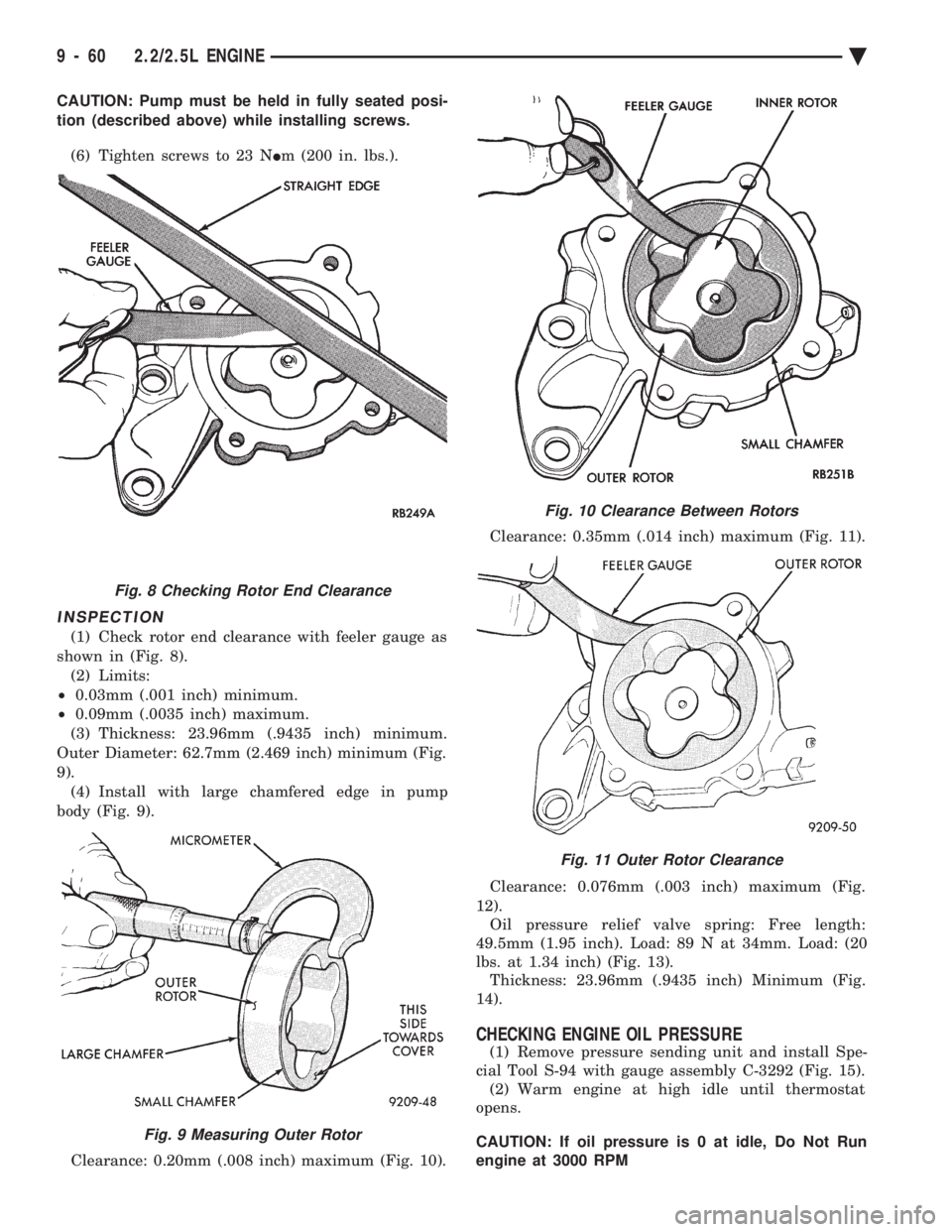
(1) Check rotor end clearance with feeler gauge as
shown in (Fig. 8). (2) Limits:
² 0.03mm (.001 inch) minimum.
² 0.09mm (.0035 inch) maximum.
(3) Thickness: 23.96mm (.9435 inch) minimum.
Outer Diameter: 62.7mm (2.469 inch) minimum (Fig.
9). (4) Install with large chamfered edge in pump
body (Fig. 9).
Clearance: 0.20mm (.008 inch) maximum (Fig. 10). Clearance: 0.35mm (.014 inch) maximum (Fig. 11).
Clearance: 0.076mm (.003 inch) maximum (Fig.
12). Oil pressure relief valve spring: Free length:
49.5mm (1.95 inch). Load: 89 N at 34mm. Load: (20
lbs. at 1.34 inch) (Fig. 13). Thickness: 23.96mm (.9435 inch) Minimum (Fig.
14).
CHECKING ENGINE OIL PRESSURE
(1) Remove pressure sending unit and install Spe-
cial Tool S-94 with gauge assembly C-3292 (Fig. 15). (2) Warm engine at high idle until thermostat
opens.
CAUTION: If oil pressure is 0 at idle, Do Not Run
engine at 3000 RPM
Fig. 8 Checking Rotor End Clearance
Fig. 9 Measuring Outer Rotor
Fig. 10 Clearance Between Rotors
Fig. 11 Outer Rotor Clearance
9 - 60 2.2/2.5L ENGINE Ä
Page 1627 of 2438
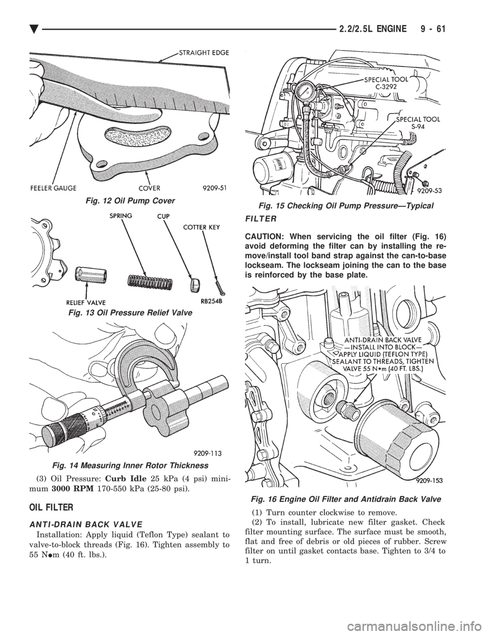
(3) Oil Pressure: Curb Idle25 kPa (4 psi) mini-
mum 3000 RPM 170-550 kPa (25-80 psi).
OIL FILTER
ANTI-DRAIN BACK VALVE
Installation: Apply liquid (Teflon Type) sealant to
valve-to-block threads (Fig. 16). Tighten assembly to
55 N Im (40 ft. lbs.).
FILTER
CAUTION: When servicing the oil filter (Fig. 16)
avoid deforming the filter can by installing the re-
move/install tool band strap against the can-to-base
lockseam. The lockseam joining the can to the base
is reinforced by the base plate.
(1) Turn counter clockwise to remove.
(2) To install, lubricate new filter gasket. Check
filter mounting surface. The surface must be smooth,
flat and free of debris or old pieces of rubber. Screw
filter on until gasket contacts base. Tighten to 3/4 to
1 turn.
Fig. 12 Oil Pump Cover
Fig. 13 Oil Pressure Relief Valve
Fig. 14 Measuring Inner Rotor Thickness
Fig. 15 Checking Oil Pump PressureÐTypical
Fig. 16 Engine Oil Filter and Antidrain Back Valve
Ä 2.2/2.5L ENGINE 9 - 61
Page 1632 of 2438
3.0L ENGINE INDEX
page page
Accessory Drive Belt Service ................ 70
Auto Lash Adjuster ....................... 75
Camshaft Service ........................ 76
Checking Engine Oil Pressure ............... 93
Crankshaft and Cylinder Block, Assembly Service . 86
Cylinder Block ........................... 89
Cylinder Head ........................... 78
Cylinder Head and Camshaft Service ......... 75
Engine Assembly ......................... 69
Engine Lubrication System ................. 91
Engine Mounts .......................... 68 Engine Specifications
..................... 95
General Information ....................... 66
Oil Filter and Bracket ..................... 94
Oil Pan ................................ 92
Oil Pump Service ........................ 92
Piston and Connecting Rod Assembly Service . . . 82
Timing Belt InspectionÐIn Vehicle ............ 72
Timing Belt Service ....................... 72
Valve Service ........................... 80
GENERAL INFORMATION
ENGINE IDENTIFICATION NUMBER OR CODE
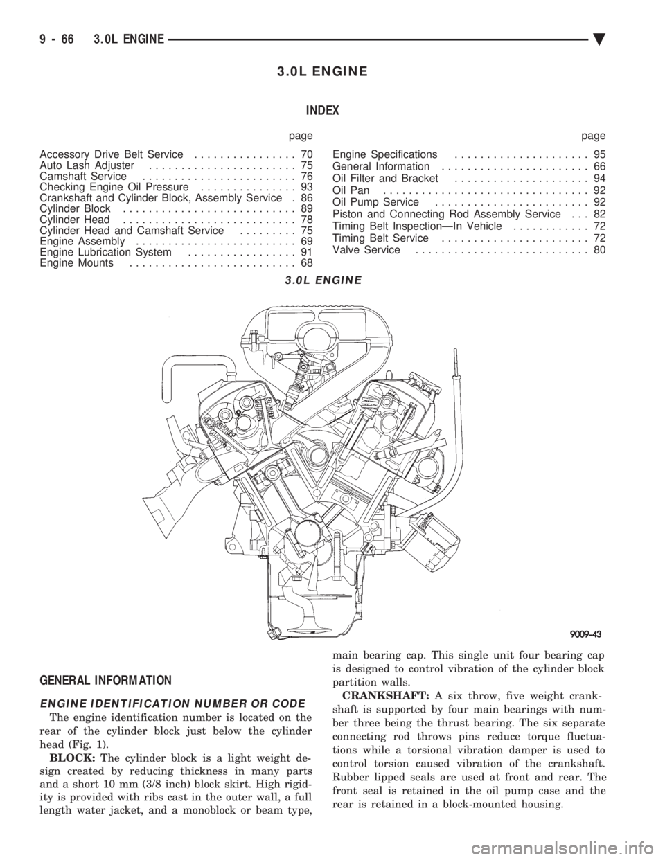
The engine identification number is located on the
rear of the cylinder block just below the cylinder
head (Fig. 1). BLOCK: The cylinder block is a light weight de-
sign created by reducing thickness in many parts
and a short 10 mm (3/8 inch) block skirt. High rigid-
ity is provided with ribs cast in the outer wall, a full
length water jacket, and a monoblock or beam type, main bearing cap. This single unit four bearing cap
is designed to control vibration of the cylinder block
partition walls.
CRANKSHAFT: A six throw, five weight crank-
shaft is supported by four main bearings with num-
ber three being the thrust bearing. The six separate
connecting rod throws pins reduce torque fluctua-
tions while a torsional vibration damper is used to
control torsion caused vibration of the crankshaft.
Rubber lipped seals are used at front and rear. The
front seal is retained in the oil pump case and the
rear is retained in a block-mounted housing.
3.0L ENGINE
9 - 66 3.0L ENGINE Ä
Page 1654 of 2438
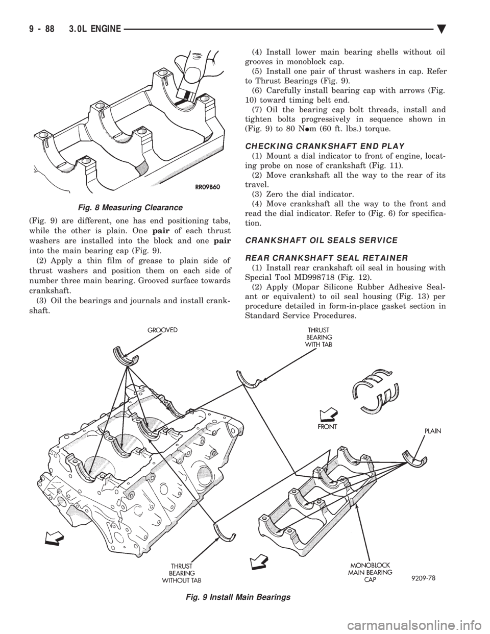
(Fig. 9) are different, one has end positioning tabs,
while the other is plain. One pairof each thrust
washers are installed into the block and one pair
into the main bearing cap (Fig. 9). (2) Apply a thin film of grease to plain side of
thrust washers and position them on each side of
number three main bearing. Grooved surface towards
crankshaft. (3) Oil the bearings and journals and install crank-
shaft. (4) Install lower main bearing shells without oil
grooves in monoblock cap. (5) Install one pair of thrust washers in cap. Refer
to Thrust Bearings (Fig. 9). (6) Carefully install bearing cap with arrows (Fig.
10) toward timing belt end. (7) Oil the bearing cap bolt threads, install and
tighten bolts progressively in sequence shown in
(Fig. 9) to 80 N Im (60 ft. lbs.) torque.
CHECKING CRANKSHAFT END PLAY
(1) Mount a dial indicator to front of engine, locat-
ing probe on nose of crankshaft (Fig. 11). (2) Move crankshaft all the way to the rear of its
travel. (3) Zero the dial indicator.
(4) Move crankshaft all the way to the front and
read the dial indicator. Refer to (Fig. 6) for specifica-
tion.
CRANKSHAFT OIL SEALS SERVICE
REAR CRANKSHAFT SEAL RETAINER
(1) Install rear crankshaft oil seal in housing with
Special Tool MD998718 (Fig. 12). (2) Apply (Mopar Silicone Rubber Adhesive Seal-
ant or equivalent) to oil seal housing (Fig. 13) per
procedure detailed in form-in-place gasket section in
Standard Service Procedures.
Fig. 9 Install Main Bearings
Fig. 8 Measuring Clearance
9 - 88 3.0L ENGINE Ä