brake pads CHEVROLET DYNASTY 1993 Service Manual
[x] Cancel search | Manufacturer: CHEVROLET, Model Year: 1993, Model line: DYNASTY, Model: CHEVROLET DYNASTY 1993Pages: 2438, PDF Size: 74.98 MB
Page 57 of 2438
flakes are visible in the used lubricant or the bearing
rollers and race cup is discolored, the bearing and
race cup should be replaced. For proper service pro-
cedures, see Group 5, Brakes. Replace the inner seal
whenever the wheel bearings are serviced.
REAR WHEEL BEARING LUBRICATION
CAUTION: Combining two types of lubricant can
cause bearing failure. Wash used or new bearings
with a suitable solvent and blot dry with a lint free
cloth before packing with new lubricant.
WARNING: DO NOT ALLOW BEARING TO SPIN AT
HIGH RPM WHEN USING COMPRESSED AIR TO
BLOW CLEANING SOLVENT FROM BEARING.
BEARING CAGE CAN EXPLODE, CAUSING PER-
SONAL INJURY.
TO LUBRICATE REAR WHEEL BEARINGS:
(1) Hoist rear wheels off the ground and support ve-
hicle on safety stands. Refer to Hoisting Recommenda-
tions in the General Information section of this group.
(2) Remove rear wheels.
(3) Remove brake caliper on vehicles with rear disc
brakes. For proper procedure, see Group 5, Brakes. (4) Remove rear wheel hub (drum) assembly and
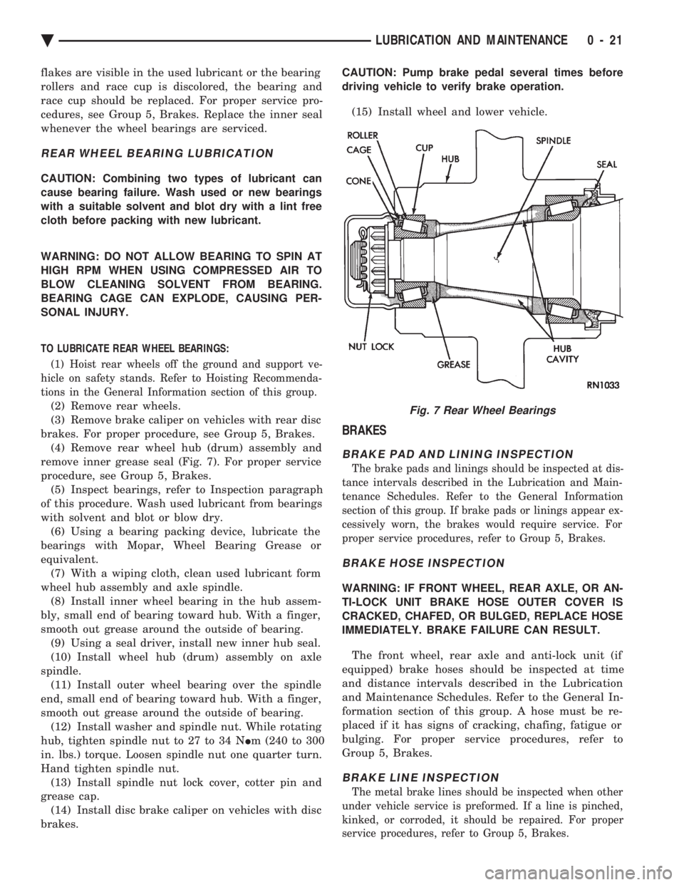
remove inner grease seal (Fig. 7). For proper service
procedure, see Group 5, Brakes. (5) Inspect bearings, refer to Inspection paragraph
of this procedure. Wash used lubricant from bearings
with solvent and blot or blow dry. (6) Using a bearing packing device, lubricate the
bearings with Mopar, Wheel Bearing Grease or
equivalent. (7) With a wiping cloth, clean used lubricant form
wheel hub assembly and axle spindle. (8) Install inner wheel bearing in the hub assem-
bly, small end of bearing toward hub. With a finger,
smooth out grease around the outside of bearing. (9) Using a seal driver, install new inner hub seal.
(10) Install wheel hub (drum) assembly on axle
spindle. (11) Install outer wheel bearing over the spindle
end, small end of bearing toward hub. With a finger,
smooth out grease around the outside of bearing. (12) Install washer and spindle nut. While rotating
hub, tighten spindle nut to 27 to 34 N Im (240 to 300
in. lbs.) torque. Loosen spindle nut one quarter turn.
Hand tighten spindle nut. (13) Install spindle nut lock cover, cotter pin and
grease cap. (14) Install disc brake caliper on vehicles with disc
brakes. CAUTION: Pump brake pedal several times before
driving vehicle to verify brake operation.
(15) Install wheel and lower vehicle.
BRAKES
BRAKE PAD AND LINING INSPECTION
The brake pads and linings should be inspected at dis-
tance intervals described in the Lubrication and Main-
tenance Schedules. Refer to the General Information
section of this group. If brake pads or linings appear ex-
cessively worn, the brakes would require service. For
proper service procedures, refer to Group 5, Brakes.
BRAKE HOSE INSPECTION
WARNING: IF FRONT WHEEL, REAR AXLE, OR AN-
TI-LOCK UNIT BRAKE HOSE OUTER COVER IS
CRACKED, CHAFED, OR BULGED, REPLACE HOSE
IMMEDIATELY. BRAKE FAILURE CAN RESULT.
The front wheel, rear axle and anti-lock unit (if
equipped) brake hoses should be inspected at time
and distance intervals described in the Lubrication
and Maintenance Schedules. Refer to the General In-
formation section of this group. A hose must be re-
placed if it has signs of cracking, chafing, fatigue or
bulging. For proper service procedures, refer to
Group 5, Brakes.
BRAKE LINE INSPECTION
The metal brake lines should be inspected when other
under vehicle service is preformed. If a line is pinched,
kinked, or corroded, it should be repaired. For proper
service procedures, refer to Group 5, Brakes.
Fig. 7 Rear Wheel Bearings
Ä LUBRICATION AND MAINTENANCE 0 - 21
Page 58 of 2438
BRAKE RESERVOIR LEVEL INSPECTION
WARNING: DO NOT ALLOW PETROLEUM OR WATER
BASE LIQUIDS TO CONTAMINATE BRAKE FLUID,
SEAL DAMAGE AND BRAKE FAILURE CAN RESULT.
RELIEVE PRESSURE IN ANTI-LOCK BRAKE SYS-
TEM BEFORE ADDING BRAKE FLUID TO RESER-
VOIR. IF NOT, BRAKE FLUID COULD DISCHARGED
FROM THE RESERVOIR POSSIBLY CAUSING PER-
SONAL INJURY.
The brake reservoir level should be inspected when
other under hood service is performed. It is normal
for the reservoir level to drop as disc brake pads
wear. When fluid must be added, use Mopar, Brake
Fluid or equivalent. Use only brake fluid conforming
to DOT 3, Federal, Department of Transportation
specification. To avoid brake fluid contamination, use
fluid from a properly sealed container. On vehicles with anti-lock brakes, depressurize the
system before inspecting fluid level. Turn OFF the
ignition and remove the key. Pump the brake pedal
at least 50 times to relieve the pressure in the sys-
tem.
On all vehicles, if fluid should become low after sev-
eral thousand kilometers (miles), fill the reservoir to
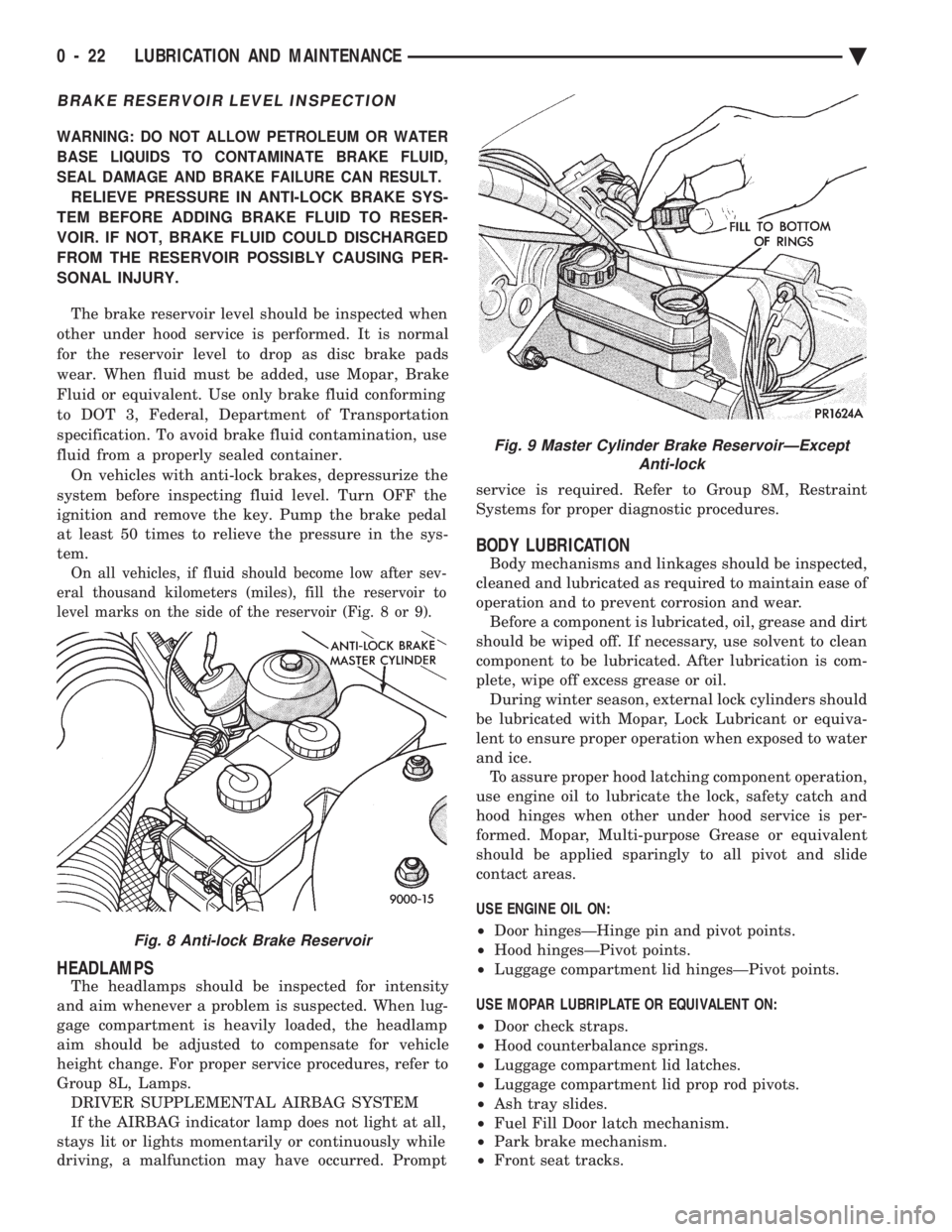
level marks on the side of the reservoir (Fig. 8 or 9).
HEADLAMPS
The headlamps should be inspected for intensity
and aim whenever a problem is suspected. When lug-
gage compartment is heavily loaded, the headlamp
aim should be adjusted to compensate for vehicle
height change. For proper service procedures, refer to
Group 8L, Lamps. DRIVER SUPPLEMENTAL AIRBAG SYSTEM
If the AIRBAG indicator lamp does not light at all,
stays lit or lights momentarily or continuously while
driving, a malfunction may have occurred. Prompt service is required. Refer to Group 8M, Restraint
Systems for proper diagnostic procedures.
BODY LUBRICATION
Body mechanisms and linkages should be inspected,
cleaned and lubricated as required to maintain ease of
operation and to prevent corrosion and wear. Before a component is lubricated, oil, grease and dirt
should be wiped off. If necessary, use solvent to clean
component to be lubricated. After lubrication is com-
plete, wipe off excess grease or oil. During winter season, external lock cylinders should
be lubricated with Mopar, Lock Lubricant or equiva-
lent to ensure proper operation when exposed to water
and ice. To assure proper hood latching component operation,
use engine oil to lubricate the lock, safety catch and
hood hinges when other under hood service is per-
formed. Mopar, Multi-purpose Grease or equivalent
should be applied sparingly to all pivot and slide
contact areas.
USE ENGINE OIL ON:
² Door hingesÐHinge pin and pivot points.
² Hood hingesÐPivot points.
² Luggage compartment lid hingesÐPivot points.
USE MOPAR LUBRIPLATE OR EQUIVALENT ON:
² Door check straps.
² Hood counterbalance springs.
² Luggage compartment lid latches.
² Luggage compartment lid prop rod pivots.
² Ash tray slides.
² Fuel Fill Door latch mechanism.
² Park brake mechanism.
² Front seat tracks.
Fig. 8 Anti-lock Brake Reservoir
Fig. 9 Master Cylinder Brake ReservoirÐExcept
Anti-lock
0 - 22 LUBRICATION AND MAINTENANCE Ä
Page 168 of 2438
REAR WHEEL DRUM BRAKES INDEX
page page
Brake Drum Refacing ..................... 21
Brake Shoe Assemblies ................... 19 Description
............................. 18
Service Procedures ....................... 18
DESCRIPTION
Rear wheel drum brakes (Fig .2&3)aretwoshoe,
internal expanding type with an automatic adjuster
screw assembly that is activated each time the
brakes are applied. The automatic adjuster screw is
located directly below the wheel cylinder as shown in
figure (Fig .2&3).
WARNING: DUST AND DIRT ON BRAKE PARTS
GENERATED DURING THE NORMAL USE AND
WEAR OF MOTOR VEHICLE BRAKE SYSTEMS MAY
CONTAIN ASBESTOS FIBERS. BREATHING EXCES-
SIVE CONCENTRATIONS OF ASBESTOS FIBERS
CAN CAUSE SERIOUS BODILY HARM, SUCH AS
ASBESTOSIS AND CANCER. EXTREME CARE
SHOULD BE EXERCISED WHILE SERVICING
BRAKE ASSEMBLIES OR COMPONENTS. DO NOT CLEAN BRAKE ASSEMBLIES OR COM-
PONENTS WITH COMPRESSED AIR OR BY DRY
BRUSHING; USE A VACUUM CLEANER SPECIFI-
CALLY RECOMMENDED FOR USE WITH ASBES-
TOS FIBERS. IF A SUITABLE VACUUM CLEANER IS
NOT AVAILABLE, CLEANING SHOULD BE DONE
WET USING A WATER DAMPENED CLOTH. DO NOT CREATE DUST BY SANDING, GRINDING,
AND/OR SHAVING BRAKE LININGS OR PADS UN-
LESS SUCH OPERATION IS DONE WHILE USING
PROPERLY EXHAUST VENTILATED EQUIPMENT. DISPOSE OF ALL DUST AND DIRT SUSPECTED
TO CONTAIN ANY ASBESTOS FIBERS IN SEALED
BAGS OR CONTAINERS TO MINIMIZE DUST EXPO-
SURE TO YOURSELF AND OTHERS. FOLLOW ALL RECOMMENDED PRACTICES PRE-
SCRIBED BY THE OCCUPATIONAL SAFETY AND
HEALTH ADMINISTRATION AND THE ENVIRON-
MENTAL PROTECTION AGENCY. FOR THE HAN-
DLING, PROCESSING, AND DISPOSITION OF DUST
OR DIRT WHICH MAY CONTAIN ASBESTOS FI-
BERS. IT IS RECOMMENDED NOT TO BREATH ANY
TYPE OF BRAKE LINING MATERIAL DUST EVEN
ASBESTOS FREE, DUE TO THE FIBROUS NATURE
OF THE MATERIALS BEING USED.
SERVICE PROCEDURES
REAR BRAKE DRUM REMOVAL
If the rear brake drum is difficult to remove, fur-
ther clearance can be obtained by backing off the
brake automatic adjuster screw. Remove rubber plug
from the top of the support plate and rotate the au-
tomatic adjuster screw assembly with an upward mo-
tion, using the Brake Adjuster, Special Tool C-3784. See adjusting rear service brakes in the Service
Adjustments section in this group of the service man-
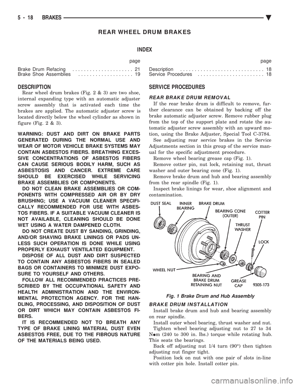
ual for the specific adjustment procedure. Remove wheel bearing grease cap (Fig. 1).
Remove cotter pin, nut lock, retaining nut, thrust
washer and outer bearing cone (Fig. 1). Remove brake drum and hub and bearing assembly
from the rear spindle (Fig. 1). Inspect brake linings for wear, shoe alignment and
contamination.
BRAKE DRUM INSTALLATION
Install brake drum and hub and bearing assembly
on rear spindle. Install outer wheel bearing, thrust washer and nut.
Tighten wheel bearing adjusting nut to 27 to 34
N Im (240 to 300 in. lbs.) torque while rotating hub.
This seats the bearings. Back off adjusting nut 1/4 turn (90É) then tighten
adjusting nut finger tight. Position lock on nut with one pair of slots in-line
with cotter pin hole. Install cotter pin.
Fig. 1 Brake Drum and Hub Assembly
5 - 18 BRAKES Ä
Page 184 of 2438
SERVICE PRECAUTIONS
WARNING: DUST AND DIRT ON BRAKE PARTS
GENERATED DURING THE NORMAL USE AND
WEAR OF MOTOR VEHICLE BRAKE SYSTEMS CAN
CONTAIN ASBESTOS FIBERS. BREATHING EXCES-
SIVE CONCENTRATIONS OF ASBESTOS FIBERS
CAN CAUSE SERIOUS BODILY HARM, SUCH AS
ASBESTOSIS AND CANCER. EXTREME CARE
SHOULD BE EXERCISED WHILE SERVICING
BRAKE ASSEMBLIES OR COMPONENTS. DO NOT CLEAN BRAKE ASSEMBLIES OR COM-
PONENTS WITH COMPRESSED AIR OR BY DRY
BRUSHING; USE A VACUUM CLEANER SPECIFI-
CALLY RECOMMENDED FOR USE WITH ASBES-
TOS FIBERS. IF A SUITABLE VACUUM CLEANER IS
NOT AVAILABLE, CLEANING SHOULD BE DONE
WET USING A WATER DAMPENED CLOTH. DO NOT CREATE DUST BY SANDING, GRINDING,
AND/OR SHAVING BRAKE LININGS OR PADS UN-
LESS SUCH OPERATION IS DONE WHILE USING
PROPERLY EXHAUST VENTILATED EQUIPMENT. DISPOSE OF ALL DUST AND DIRT SUSPECTED
TO CONTAIN ANY ASBESTOS FIBERS IN SEALED
BAGS OR CONTAINERS TO MINIMIZE DUST EXPO-
SURE TO YOURSELF AND OTHERS. FOLLOW ALL RECOMMENDED PRACTICES PRE-
SCRIBED BY THE OCCUPATIONAL SAFETY AND
HEALTH ADMINISTRATION AND THE ENVIRONMEN-
TAL PROTECTION AGENCY. FOR THE HANDLING,
PROCESSING, AND DISPOSITION OF DUST OR DIRT
WHICH MAY CONTAIN ASBESTOS FIBERS. IT IS RECOMMENDED NOT TO BREATH ANY TYPE
OF BRAKE LINING MATERIAL DUST EVEN ASBES-
TOS FREE, DUE TO THE FIBROUS NATURE OF THE
MATERIALS BEING USED.
Grease or any other foreign material must be kept off
caliper assembly, surfaces of braking disc and external
surfaces of hub, during service procedures. Handling of the braking disc and caliper. Should be
done in such a way as to avoid deformation of the disc
and scratching or nicking of the brake linings. If inspection reveals that the square sectioned cali-
per piston seal is worn or damaged, it should be
replaced immediately. During removal and installation of a wheel and tire
assembly, use care not to strike the caliper. Before vehicle is moved after any brake service
work, be sure to obtain a firm brake pedal.
5 - 34 BRAKES Ä
Page 196 of 2438
removal will be necessary. Remove the shoe and lin-
ing assemblies (see Brake Shoe Removal).Combined shoe and lining thickness should be
measured at the thinnest part of the assembly. When a shoe and lining assembly is worn to a
thickness of approximately 7.0 mm (9/32 inch) it
should be replaced. Replace both shoe assemblies (inboard and out-
board) on both wheels whenever shoe assemblies on
either side are replaced. If a shoe assembly does not require replacement.
Reinstall it, making sure each shoe assembly is re-
turned to its original position on the wheel of the ve-
hicle from which it was removed. (See Brake Shoe
Installation).
SERVICE PRECAUTIONS
WARNING: DUST AND DIRT ON BRAKE PARTS
GENERATED DURING THE NORMAL USE AND
WEAR OF MOTOR VEHICLE BRAKE SYSTEMS CAN
CONTAIN ASBESTOS FIBERS. BREATHING EXCES-
SIVE CONCENTRATIONS OF ASBESTOS FIBERS
CAN CAUSE SERIOUS BODILY HARM, SUCH AS
ASBESTOSIS AND CANCER. EXTREME CARE
SHOULD BE EXERCISED WHILE SERVICING
BRAKE ASSEMBLIES OR COMPONENTS. DO NOT CLEAN BRAKE ASSEMBLIES OR COM-
PONENTS WITH COMPRESSED AIR OR BY DRY
BRUSHING; USE A VACUUM CLEANER SPECIFI-
CALLY RECOMMENDED FOR USE WITH ASBES-
TOS FIBERS. IF A SUITABLE VACUUM CLEANER IS
NOT AVAILABLE, CLEANING SHOULD BE DONE
WET USING A WATER DAMPENED CLOTH. DO NOT CREATE DUST BY SANDING, GRINDIN-
G,AND/OR SHAVING BRAKE LININGS OR PADS
UNLESS SUCH OPERATION IS DONE WHILE USING
PROPERLY EXHAUST VENTILATED EQUIPMENT. DISPOSE OF ALL DUST AND DIRT SUSPECTED
TO CONTAIN ANY ASBESTOS FIBERS IN SEALED
BAGS OR CONTAINERS TO MINIMIZE DUST EXPO-
SURE TO YOURSELF AND OTHERS. FOLLOW ALL RECOMMENDED PRACTICES PRE-
SCRIBED BY THE OCCUPATIONAL SAFETY AND
HEALTH ADMINISTRATION AND THE ENVIRON-
MENTAL PROTECTION AGENCY. FOR THE HAN-
DLING, PROCESSING, AND DISPOSITION OF DUST
OR DIRT WHICH MAY CONTAIN ASBESTOS FI-
BERS. IT IS RECOMMENDED NOT TO BREATH ANY
TYPE OF BRAKE LINING MATERIAL DUST EVEN
ASBESTOS FREE, DUE TO THE FIBROUS NATURE
OF THE MATERIALS BEING USED.
Grease or any other foreign material must be kept
off the caliper assembly, surfaces of the braking disc
and external surfaces of the hub, during service pro-
cedures. Handling the braking disc and caliper should be done
in such a way as to avoid deformation of the disc and
scratching or nicking the brake linings (pads). During removal and installation of a wheel and tire
assembly, use care not to strike the caliper. Before vehicle is moved after any brake service
work, be sure to obtain a firm brake pedal.
BRAKE SHOE REMOVAL
(1) Raise vehicle on jackstands or centered on a
hoist. (2) Remove rear wheel and tire assemblies.
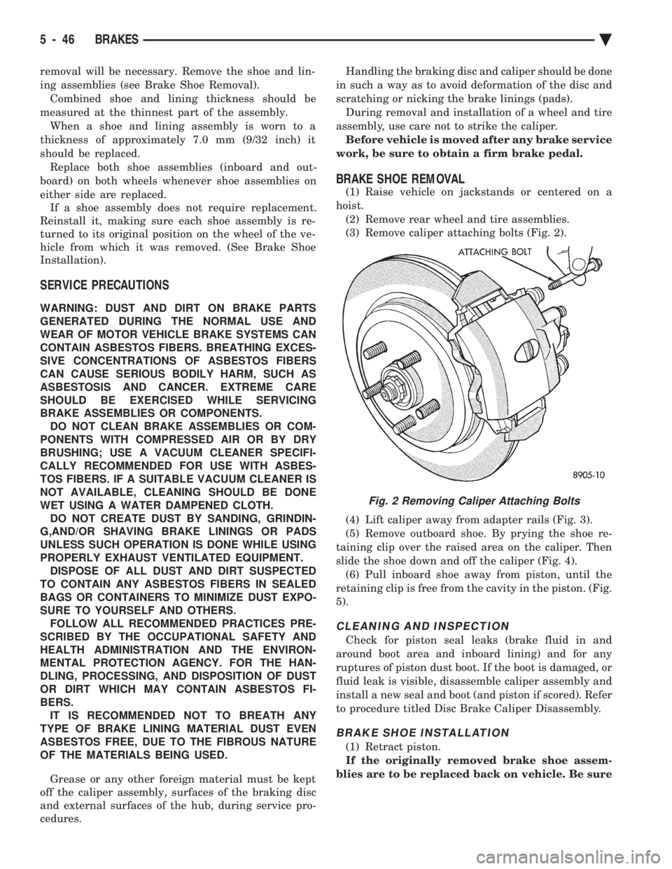
(3) Remove caliper attaching bolts (Fig. 2).
(4) Lift caliper away from adapter rails (Fig. 3).
(5) Remove outboard shoe. By prying the shoe re-
taining clip over the raised area on the caliper. Then
slide the shoe down and off the caliper (Fig. 4). (6) Pull inboard shoe away from piston, until the
retaining clip is free from the cavity in the piston. (Fig.
5).
CLEANING AND INSPECTION
Check for piston seal leaks (brake fluid in and
around boot area and inboard lining) and for any
ruptures of piston dust boot. If the boot is damaged, or
fluid leak is visible, disassemble caliper assembly and
install a new seal and boot (and piston if scored). Refer
to procedure titled Disc Brake Caliper Disassembly.
BRAKE SHOE INSTALLATION
(1) Retract piston.
If the originally removed brake shoe assem-
blies are to be replaced back on vehicle. Be sure
Fig. 2 Removing Caliper Attaching Bolts
5 - 46 BRAKES Ä