lights CHEVROLET DYNASTY 1993 Owner's Manual
[x] Cancel search | Manufacturer: CHEVROLET, Model Year: 1993, Model line: DYNASTY, Model: CHEVROLET DYNASTY 1993Pages: 2438, PDF Size: 74.98 MB
Page 1065 of 2438
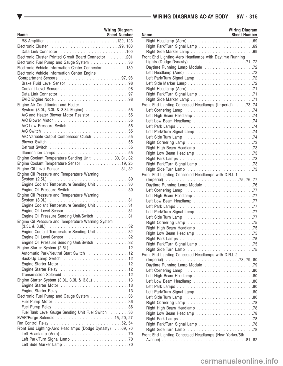
Wiring Diagram
Name Sheet Number
RS Amplifier ......................... .122, 123
Electronic Cluster ........................ .99, 100
Data Link Connector ....................... .100
Electronic Cluster Printed Circuit Board Connector .......201
Electronic Fuel Pump and Gauge System ..............36
Electronic Vehicle Information Center Connector ........189
Electronic Vehicle Information Center Engine Compartment Sensors ...................... .97, 98
Brake Fluid Level Sensor ......................98
Coolant Level Sensor .........................98
Data Link Connector .........................97
EVIC Engine Node ...........................98
Engine Air Conditioning and Heater System (3.0L, 3.3L & 3.8L Engine) ................55
A/C and Heater Blower Motor Resistor ..............55
A/C Blower Motor ...........................55
A/C Low Pressure Switch ......................55
A/C Switch ...............................55
A/C Variable Output Compressor Clutch .............55
Blower Switch .............................55
Defrost Switch .............................55
Illumination Lamps ..........................55
Engine Coolant Temperature Sending Unit ........30, 31, 32
Engine Coolant Temperature Sensor ..............19, 25
Engine Oil Level Sensor ..................... .31, 32
Engine Oil Pressure and Temperature Warning System (2.5L) .............................30
Engine Coolant Temperature Sending Unit ............30
Engine Oil Pressure Switch .....................30
Engine Oil Pressure and Temperature Warning System (3.0L) .............................31
Engine Coolant Temperature Sending Unit ............31
Engine Oil Level Sensor .......................31
Engine Oil Pressure Sending Unit/Switch ............31
Engine Oil Pressure and Temperature Warning System (3.3L & 3.8L) .............................32
Engine Coolant Temperature Sending Unit ............32
Engine Oil Level Sensor .......................32
Engine Oil Pressure Sending Unit/Switch ............32
Engine Starter System (2.5L) .....................12
Automatic Park/Neutral Start Switch ...............12
Back-Up Lamp Switch ........................12
Engine Starter Motor .........................12
Engine Starter Relay .........................12
Transmission Solenoid ........................12
Engine Starter System (3.0L, 3.3L & 3.8L) .............13
Engine Starter Motor .........................13
Engine Starter Relay .........................13
Electronic Fuel Pump and Gauge System ..............36
Fuel Pump Motor ...........................36
Fuel Pump Relay ...........................36
Fuel Tank Level Gauge Sending Unit Fuel Switch .......36
EVAP/Purge Solenoid .................... .15, 20, 27
Fan Control Relay ......................... .52, 54
Front End Lighting-Aero Headlamps (Dodge Dynasty) . . .69, 70 Left Headlamp (Aero) .........................70
Left Park/Turn Signal Lamp .....................70
Left Side Marker Lamp ........................70Wiring Diagram
Name Sheet Number
Right Headlamp (Aero) ........................69
Right Park/Turn Signal Lamp ....................69
Right Side Marker Lamp .......................69
Front End Lighting-Aero Headlamps with Daytime Running Lights (Dodge Dynasty) .................... .71, 72
Daytime Running Lamp Module ..................72
Left Headlamp (Aero) .........................72
Left Park/Turn Signal Lamp .....................72
Left Side Marker Lamp ........................72
Right Headlamp (Aero) ........................71
Right Park/Turn Signal Lamp ....................71
Right Side Marker Lamp .......................71
Front End Lighting Concealed Headlamps (Imperial) . . . .73, 74
Left Cornering Lamp .........................74
Left High Beam Headlamp ......................74
Left Low Beam Headlamp ......................74
Left Park Lamps ............................74
Left Park/Turn Signal Lamp .....................74
Left Side Turn Lamp .........................74
Right Cornering Lamp ........................73
Right High Beam Headlamp .....................73
Right Low Beam Headlamp .....................73
Right Park Lamps ...........................73
Right Park/Turn Signal Lamp ....................73
Right Side Turn Lamp ........................73
Front End Lighting Concealed Headlamps with D.R.L.1 (Imperial) .......................... .75, 76, 77
Daytime Running Lamp Module ..................76
Left Cornering Lamp .........................77
Left High Beam Headlamp ......................77
Left Low Beam Headlamp ......................77
Left Park Lamps ............................77
Left Park/Turn Signal Lamp .....................77
Left Side Turn Lamp .........................77
Right Cornering Lamp ........................75
Right High Beam Headlamp .....................75
Right Low Beam Headlamp .....................75
Right Park Lamps ...........................75
Right Park/Turn Signal Lamp ....................75
Right Side Turn Lamp ........................75
Front End Lighting Concealed Headlamps with D.R.L.2 (Imperial) .......................... .78, 79, 80
Daytime Running Lamp Module ..................79
Left Cornering Lamp .........................80
Left High Beam Headlamp ......................80
Left Low Beam Headlamp ......................80
Left Park Lamps ............................80
Left Park/Turn Signal Lamp .....................80
Left Side Turn Lamp .........................80
Right Cornering Lamp ........................78
Right High Beam Headlamp .....................78
Right Low Beam Headlamp .....................78
Right Park Lamps ...........................78
Right Park/Turn Signal Lamp ....................78
Right Side Turn Lamp ........................78
Front End Lighting Concealed Headlamps (New Yorker/5th Avenue) .............................. .81, 82
Ä WIRING DIAGRAMS AC-AY BODY 8W - 315
Page 1283 of 2438
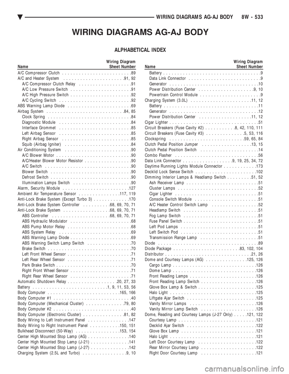
WIRING DIAGRAMS AG-AJ BODY
ALPHABETICAL INDEX
Wiring Diagram
Name Sheet Number
A/C Compressor Clutch .........................89
A/C and Heater System ..................... .91, 92
A/C Compressor Clutch Relay ...................91
A/C Low Pressure Switch ......................91
A/C High Pressure Switch ......................92
A/C Cycling Switch ..........................92
ABS Warning Lamp Diode .......................69
Airbag System ........................... .84, 85
Clock Spring ..............................84
Diagnostic Module ..........................84
Interface Grommet ..........................85
Left Airbag Sensor ..........................85
Right Airbag Sensor .........................85
Squib (Airbag Igniter) ........................84
Air Conditioning System ........................90
A/C Blower Motor ...........................90
A/C/Heater Blower Motor Resistor .................90
A/C Switch ...............................90
Blower Switch .............................90
Defrost Switch .............................90
Illumination Lamps Switch .....................90
Alarm, Security Module ....................... .127
Ambient Air Temperature Sensor ...............117, 119
Anti-Lock Brake System (Except Turbo 3) .............170
Anti-Lock Brake System Controller ..........68, 69, 70, 71
Anti-Lock Brake System .................68, 69, 70, 71
ABS Controller .................... .68, 69, 70, 71
ABS Hydraulic Modulator ......................68
ABS Pump Motor Relay .......................68
ABS System Relay ..........................69
ABS Warning Lamp Diode ......................69
ABS Warning Switch Lamp Switch ................70
Brake Switch ..............................70
Left Front Wheel Sensor .......................71
Left Rear Wheel Sensor .......................71
Park Brake Switch ...........................70
Right Front Wheel Sensor ......................71
Right Rear Wheel Sensor ......................71
Automatic Shutdown Relay ..................20, 27, 33
Battery ...........................1,9,11,53,56
Body Computer ......................... .165, 166
Body Computer #1 ............................40
Body Computer (Mechanical Cluster) ..............79, 80
Body Computer #2 ............................40
Body Computer (Electronic Cluster) ...............81, 82
Body Wiring to Left Instrument Panel ...............147
Body Wiring to Right Instrument Panel ...........150, 151
Bulkhead Disconnect (50-Way) ................153, 154
Center High Mounted Stop Lamp (AG) ...............140
Center High Mounted Stop Lamp (J-21) ..............141
Center High Mounted Stop Lamp (J-27) ..............142
Charging System (2.5L and Turbo) ................9,10Wiring Diagram
Name Sheet Number
Battery ...................................9
Data Link Connector ..........................9
Generator ................................10
Power Distribution Center ....................9,10
Powertrain Control Module ......................9
Charging System (3.0L) ..................... .11, 12
Battery ..................................11
Generator ................................12
Power Distribution Center .................. .11, 12
Cigar Lighter ................................51
Circuit Breakers (Fuse Cavity #2) ...........8,42,110, 111
Circuit Breakers (Fuse Cavity #3) ..............5,53,116
Clockspring .......................... .59, 65, 84
Clutch Pedal Position Jumper ..................13, 15
Clutch Pedal Position Switch .....................14
Combo Flasher ..............................56
Data Link Connector ..................9,19,25,34,72
Daytime Running Lights Module Connector ............173
Decklid Lock Sense Switch ..................... .102
Dimming Interior Lamps & Headlamp Switch .........51, 52
Ash Receiver Lamp ..........................51
Cluster Lamps .............................52
Cigar Lighter ..............................51
Console Switch Module .......................51
A/C Heater Control Switch Lamp .................52
Headlamp Switch ...........................51
Fog Lamp Switch ...........................51
Fuse Panel Switch ...........................51
Left Pod Lamps ............................51
Left Switch Pod ............................51
Transmission Range Lamp .....................51
Diode ....................................89
Diode Package ....................... .83, 102, 104
Distributor .............................. .21, 26
Dome and Courtesy Lamps (AG) ...............125, 126
Cargo Lamp ............................. .126
Dome Lamp ............................. .126
Front Reading Lamps ....................... .126
Front Reading Lamp Switch ................... .126
Glove Box Lamp & Switch .................... .125
Halo Light .............................. .125
Liftgate Ajar Switch ........................ .125
Vanity Mirror Lamps ....................... .126
Vanity Mirror Lamp Switch ................... .126
Dome, Reading and Courtesy Lamps (J-27 Only) .....121, 122
Courtesy Lamp ........................... .121
Decklid Ajar Switch ........................ .122
Glove Box Lamp .......................... .121
Halo Light .............................. .121
Left Door Courtesy Lamp .................... .122
Rear Mirror Courtesy Lamp ................... .122
Right Door Courtesy Lamp ................... .121
Ä WIRING DIAGRAMS AG-AJ BODY 8W - 533
Page 1467 of 2438
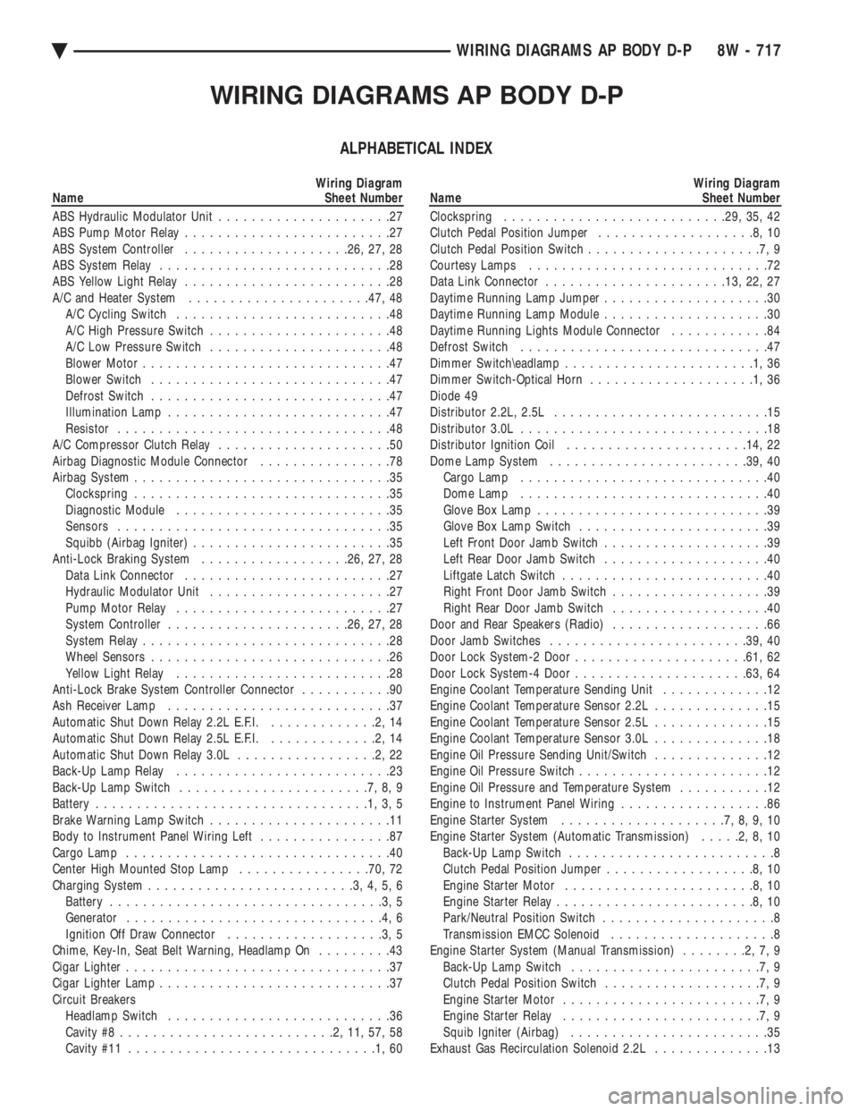
WIRING DIAGRAMS AP BODY D-P
ALPHABETICAL INDEX
Wiring Diagram
Name Sheet Number
ABS Hydraulic Modulator Unit .....................27
ABS Pump Motor Relay .........................27
ABS System Controller ................... .26, 27, 28
ABS System Relay ............................28
ABS Yellow Light Relay .........................28
A/C and Heater System ..................... .47, 48
A/C Cycling Switch ..........................48
A/C High Pressure Switch ......................48
A/C Low Pressure Switch ......................48
Blower Motor ..............................47
Blower Switch .............................47
Defrost Switch .............................47
Illumination Lamp ...........................47
Resistor .................................48
A/C Compressor Clutch Relay .....................50
Airbag Diagnostic Module Connector ................78
Airbag System ...............................35
Clockspring ...............................35
Diagnostic Module ..........................35
Sensors .................................35
Squibb (Airbag Igniter) ........................35
Anti-Lock Braking System ..................26, 27, 28
Data Link Connector .........................27
Hydraulic Modulator Unit ......................27
Pump Motor Relay ..........................27
System Controller ..................... .26, 27, 28
System Relay ..............................28
Wheel Sensors .............................26
Yellow Light Relay ..........................28
Anti-Lock Brake System Controller Connector ...........90
Ash Receiver Lamp ...........................37
Automatic Shut Down Relay 2.2L E.F.I. .............2,14
Automatic Shut Down Relay 2.5L E.F.I. .............2,14
Automatic Shut Down Relay 3.0L .................2,22
Back-Up Lamp Relay ..........................23
Back-Up Lamp Switch .......................7,8,9
Battery .................................1,3,5
Brake Warning Lamp Switch ......................11
Body to Instrument Panel Wiring Left ................87
Cargo Lamp ................................40
Center High Mounted Stop Lamp ................70, 72
Charging System .........................3,4,5,6
Battery .................................3,5
Generator ...............................4,6
Ignition Off Draw Connector ...................3,5
Chime, Key-In, Seat Belt Warning, Headlamp On .........43
Cigar Lighter ................................37
Cigar Lighter Lamp ............................37
Circuit Breakers Headlamp Switch ...........................36
Cavity #8 ..........................2,11,57,58
Cavity #11 ..............................1,60Wiring Diagram
Name Sheet Number
Clockspring .......................... .29, 35, 42
Clutch Pedal Position Jumper ...................8,10
Clutch Pedal Position Switch .....................7,9
Courtesy Lamps .............................72
Data Link Connector ..................... .13, 22, 27
Daytime Running Lamp Jumper ....................30
Daytime Running Lamp Module ....................30
Daytime Running Lights Module Connector ............84
Defrost Switch ..............................47
Dimmer Switch\eadlamp .......................1,36
Dimmer Switch-Optical Horn ....................1,36
Diode 49
Distributor 2.2L, 2.5L ..........................15
Distributor 3.0L ..............................18
Distributor Ignition Coil ..................... .14, 22
Dome Lamp System ....................... .39, 40
Cargo Lamp ..............................40
Dome Lamp ..............................40
Glove Box Lamp ............................39
Glove Box Lamp Switch .......................39
Left Front Door Jamb Switch ....................39
Left Rear Door Jamb Switch ....................40
Liftgate Latch Switch .........................40
Right Front Door Jamb Switch ...................39
Right Rear Door Jamb Switch ...................40
Door and Rear Speakers (Radio) ...................66
Door Jamb Switches ....................... .39, 40
Door Lock System-2 Door .................... .61, 62
Door Lock System-4 Door .................... .63, 64
Engine Coolant Temperature Sending Unit .............12
Engine Coolant Temperature Sensor 2.2L ..............15
Engine Coolant Temperature Sensor 2.5L ..............15
Engine Coolant Temperature Sensor 3.0L ..............18
Engine Oil Pressure Sending Unit/Switch ..............12
Engine Oil Pressure Switch .......................12
Engine Oil Pressure and Temperature System ...........12
Engine to Instrument Panel Wiring ..................86
Engine Starter System ....................7,8,9,10
Engine Starter System (Automatic Transmission) .....2,8,10
Back-Up Lamp Switch .........................8
Clutch Pedal Position Jumper ..................8,10
Engine Starter Motor .......................8,10
Engine Starter Relay ........................8,10
Park/Neutral Position Switch .....................8
Transmission EMCC Solenoid ....................8
Engine Starter System (Manual Transmission) ........2,7,9
Back-Up Lamp Switch .......................7,9
Clutch Pedal Position Switch ...................7,9
Engine Starter Motor ........................7,9
Engine Starter Relay ........................7,9
Squib Igniter (Airbag) ........................35
Exhaust Gas Recirculation Solenoid 2.2L ..............13
Ä WIRING DIAGRAMS AP BODY D-P 8W - 717
Page 1952 of 2438
(16) Connect the battery ground (negative) cable.
Test the operation of the lights and horns. If applica-
ble, reset the clock and radio.
STEERING COLUMN COMPONENT SERVICE
The Acustar tilt and standard steering columns
(Fig.1) have been designed to be serviced as an as-
sembly; less wiring, switches, shrouds, steering
wheel, etc. Also most steering column components
can be serviced without removing the steering col-
umn from the vehicle. For additional information on
electrical components refer to Group 8H Electrical.
GEAR SHIFT LEVER
The gear shift lever (if equipped) is a serviceable
component of the Acustar steering column assembly.
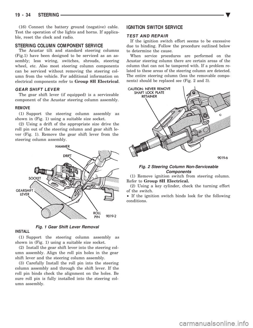
REMOVE (1) Support the steering column assembly as
shown in (Fig. 1) using a suitable size socket. (2) Using a drift of the appropriate size drive the
roll pin out of the steering column and gear shift le-
ver (Fig. 1). Remove the gear shift lever from the
steering column assembly.
INSTALL (1) Support the steering column assembly as
shown in (Fig. 1) using a suitable size socket. (2) Install the gear shift lever into the steering col-
umn assembly. Align the roll pin holes in the gear
shift lever and the steering column assembly. (3) Carefully Install the roll pin into the steering
column assembly and through the shift lever. If the
roll pin binds check the alignment on the holes. Be
sure roll pin is fully installed into the steering col-
umn assembly.
IGNITION SWITCH SERVICE
TEST AND REPAIR
If the ignition switch effort seems to be excessive
due to binding. Follow the procedure outlined below
to determine the cause.
When service procedures are performed on the
Acustar steering column there are certain areas of the
column that can not be tampered with. If a problem re-
lated to these areas of the steering column are detected.
The entire steering column (less the removable compo-
nents) should be replaced see (Fig. 2 and 3).
(1) Remove ignition switch from steering column.
Refer to Group 8H Electrical.
(2) Using a key cylinder, check the turning effort
of the switch.
² If the ignition switch binds look for the following
conditions.
Fig. 1 Gear Shift Lever Removal
Fig. 2 Steering Column Non-Serviceable Components
19 - 34 STEERING Ä
Page 2063 of 2438
SPEED SENSOR-OUTPUT
CAUTION: When disconnecting speed sensor con-
nector, be sure that the weather seal does not fall
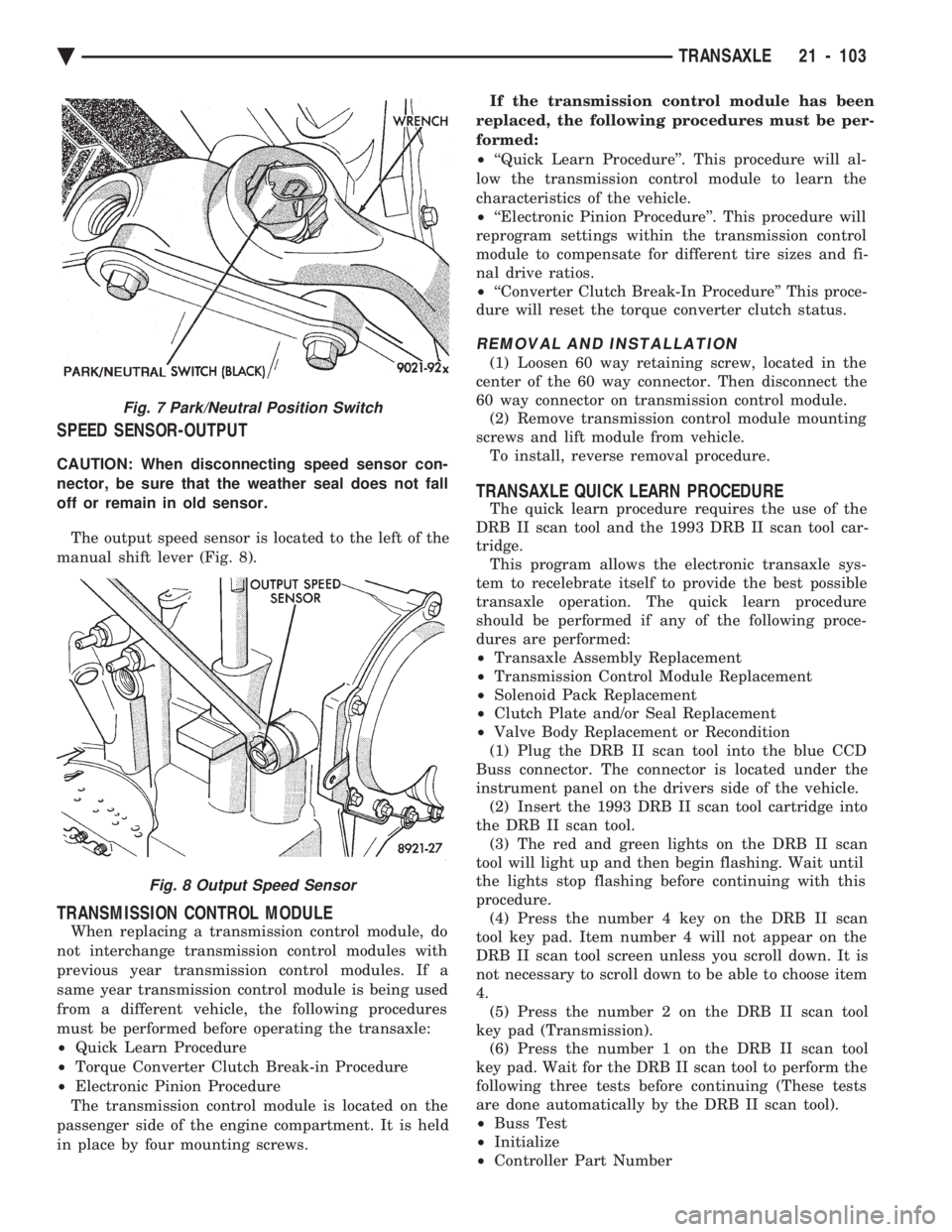
off or remain in old sensor. The output speed sensor is located to the left of the
manual shift lever (Fig. 8).
TRANSMISSION CONTROL MODULE
When replacing a transmission control module, do
not interchange transmission control modules with
previous year transmission control modules. If a
same year transmission control module is being used
from a different vehicle, the following procedures
must be performed before operating the transaxle:
² Quick Learn Procedure
² Torque Converter Clutch Break-in Procedure
² Electronic Pinion Procedure
The transmission control module is located on the
passenger side of the engine compartment. It is held
in place by four mounting screws. If the transmission control module has been
replaced, the following procedures must be per-
formed:
² ``Quick Learn Procedure''. This procedure will al-
low the transmission control module to learn the
characteristics of the vehicle.
² ``Electronic Pinion Procedure''. This procedure will
reprogram settings within the transmission control
module to compensate for different tire sizes and fi-
nal drive ratios.
² ``Converter Clutch Break-In Procedure'' This proce-
dure will reset the torque converter clutch status.
REMOVAL AND INSTALLATION
(1) Loosen 60 way retaining screw, located in the
center of the 60 way connector. Then disconnect the
60 way connector on transmission control module. (2) Remove transmission control module mounting
screws and lift module from vehicle. To install, reverse removal procedure.
TRANSAXLE QUICK LEARN PROCEDURE
The quick learn procedure requires the use of the
DRB II scan tool and the 1993 DRB II scan tool car-
tridge. This program allows the electronic transaxle sys-
tem to recelebrate itself to provide the best possible
transaxle operation. The quick learn procedure
should be performed if any of the following proce-
dures are performed:
² Transaxle Assembly Replacement
² Transmission Control Module Replacement
² Solenoid Pack Replacement
² Clutch Plate and/or Seal Replacement
² Valve Body Replacement or Recondition
(1) Plug the DRB II scan tool into the blue CCD
Buss connector. The connector is located under the
instrument panel on the drivers side of the vehicle. (2) Insert the 1993 DRB II scan tool cartridge into
the DRB II scan tool. (3) The red and green lights on the DRB II scan
tool will light up and then begin flashing. Wait until
the lights stop flashing before continuing with this
procedure. (4) Press the number 4 key on the DRB II scan
tool key pad. Item number 4 will not appear on the
DRB II scan tool screen unless you scroll down. It is
not necessary to scroll down to be able to choose item
4. (5) Press the number 2 on the DRB II scan tool
key pad (Transmission). (6) Press the number 1 on the DRB II scan tool
key pad. Wait for the DRB II scan tool to perform the
following three tests before continuing (These tests
are done automatically by the DRB II scan tool).
² Buss Test
² Initialize
² Controller Part Number
Fig. 7 Park/Neutral Position Switch
Fig. 8 Output Speed Sensor
Ä TRANSAXLE 21 - 103
Page 2064 of 2438
(7) Press the number 5 on the DRB II scan tool
key pad (Adjustments). (8) Press the number 3 on the DRB II scan tool
key pad (Quick Learn). Then follow the instructions
on the DRB II scan tool screen.
PINION FACTOR PROCEDURE
The vehicle speed readings for the speedometer are
taken from the output speed sensor. Because of dif-
ferent tire sizes and final drive ratios, the transmis-
sion control module must be calibrated to reflect the
different combinations of equipment. A procedure has
been developed called Pinion Factor. It allows the
technician to set the transmission control module ini-
tial setting so that the speedometer readings will be
correct. Failure to perform this procedure will cause a ``No
Speedometer Operation'' condition. This procedure must be performed if the transmis-
sion control module has been replaced. To properly read or reset the Pinion Factor, it is
necessary to use a DRB II scan tool. Perform the fol-
lowing steps with the DRB II scan tool to read or re-
set the Pinion Factor: (1) Plug the DRB II scan tool into the blue CCD
Bus connector. The connector is located under the in-
strument panel on the drivers side of the vehicle. (2) Insert the 1993 DRB II scan tool cartridge into
the DRB II scan tool. (3) The red and green lights on the DRB II scan
tool will light up and then begin flashing. Wait until
the lights stop flashing before continuing with this
procedure. (4) Press the number 4 key (Select System) on the
DRB II scan tool key pad. Item number 4 will not ap-
pear on the DRB II scan tool screen unless you scroll
down. It is not necessary to scroll down to be able to
choose item 4. (5) Press the number 2 on the DRB II scan tool
key pad (Transmission). (6) Press the number 1 on the DRB II scan tool
key pad. Wait for the DRB II scan tool to perform the
following three tests before continuing (These tests
are done automatically by the DRB II scan tool).
² Bus Test
² Initialize
² Transmission Control Module Part Number
(7) Press the number 5 on the DRB II scan tool
key pad (Adjustments). (8) Press the number 2 on the DRB II scan tool
key pad (Pinion Factor). Then follow the instructions
on the DRB II scan tool screen.
TORQUE CONVERTER CLUTCH BREAK-IN
PROCEDURE
A torque converter clutch break-in program is be-
ing used on all models with a 41TE. This program
will properly condition the torque converter clutch. This will eliminate shudder during partial torque
converter clutch operation on a new torque converter.
If the torque converter is replaced, the new clutch
within the torque converter will require break-in.
The current break-in status stored in the transmis-
sion control module will have to be reset to the start
of break-in with the DRB II scan tool. If a new transmission control module is put on the
vehicle, the status will be at the start of break-in.
This status is acceptable regardless of the mileage on
the torque converter. No modification of the break-in
status is required. To properly service these vehicles, it is necessary to
use a DRB II scan tool to read or reset the break-in
status. Perform the following steps with the DRB II
scan tool to reset the break-in status: (1) Plug the DRB II scan tool into the blue CCD
Bus connector. The connector is located under the in-
strument panel on the drivers side of the vehicle. (2) Insert the 1993 DRB II scan tool cartridge into
the DRB II scan tool. (3) The red and green lights on the DRB II scan
tool will light up and then begin flashing. Wait until
the lights stop flashing before continuing with this
procedure. (4) Press the number 4 key (Select System) on the
DRB II scan tool key pad. Item number 4 will not ap-
pear on the DRB II scan tool screen unless you scroll
down. It is not necessary to scroll down to be able to
choose item 4. (5) Press the number 2 on the DRB II scan tool
key pad (Transmission). (6) Press the number 1 on the DRB II scan tool
key pad. Wait for the DRB II scan tool to perform the
following three tests before continuing (These tests
are done automatically by the DRB II scan tool).
² Bus Test
² Initialize
² Transmission Control Module Part Number
(7) Press the number 5 on the DRB II scan tool
key pad (Adjustments). (8) Press the number 1 on the DRB II scan tool
key pad (Reset LU Clutch). The DRB II scan tool will
display one of three screens. (a) LU Clutch Break-in Status: Start
(b) LU Clutch Break-in Status: In-progress
Press ENTER to Reset Break-in status (c) LU Clutch Break-in Status: CompletePress
ENTER to Reset Break-in status
If screen (a) appears, the transmission control mod-
ule is at the beginning of its break-in program. No
further action is required. If screen (b) appears, the transmission control mod-
ule is in the middle of a its break-in program. Press
the enter key on the DRB II scan tool key pad to re-
turn the status to the start of break-in.
21 - 104 TRANSAXLE Ä
Page 2158 of 2438
BODY DIAGNOSTIC PROCEDURES INDEX
page page
Water Leaks ............................. 2 Wind Noise.............................. 3
WATER LEAKS
Water leaks can be caused by poor sealing, improper
body component alignment, body seam porosity, miss-
ing plugs, or blocked drain holes. Centrifugal and
gravitational force can cause water to drip from an
area somewhat distant from the actual leak point,
making leak detection difficult. All body sealing points
should be water tight in normal wet driving conditions.
Water flowing downward from the front of the vehicle
should not enter the passenger or luggage compart-
ment. Moving sealing surfaces will not always seal
water tight under all conditions. At times, side glass,
door, or convertible top seals will allow water to enter
the passenger compartment during high pressure
washing or hard driving rain (severe) conditions. Over
compensating on door, glass, or top adjustments to stop
a water leak that occurs under severe conditions, can
cause premature seal wear and excessive closing or
latching effort. After a repair procedure has been
performed, water test vehicle to verify leak has stopped
before returning vehicle to use.
VISUAL INSPECTION BEFORE WATER LEAK TESTS
Verify that floor and body plugs are in place, body
drains are clear and body components are aligned and
sealed. If component alignment or sealing is necessary,
refer to the appropriate section of this group for proper
procedures.
WATER LEAK TESTS
WARNING: DO NOT USE ELECTRIC SHOP LIGHTS
OR TOOLS IN WATER TEST AREA, PERSONAL IN-
JURY CAN RESULT.
When a determination has been made on the condi-
tions that a water leak occurs, simulate the conditions
as closely as possible.
² If a leak occurs when the car is parked in a steady
light rain, flood the leak area with a open ended garden
hose.
² If a leak occurs at highway speeds in a steady rain,
test the leak area with a stream or fan spray of water
from a garden hose with an adjustable nozzle. Direct
the spray in the direction comparable to actual condi-
tions. ²
If a leak seems to occur only when the vehicle is
parked on an incline, hoist the end or side of the vehicle
to simulate this condition before water testing. This
method can also be used when the leak occurs when the
vehicle accelerates, stops, or turns. If the leak occurs
on acceleration, hoist the front of the vehicle. If the
leak occurs when braking, hoist the back of the vehicle.
If the leak occurs on left turns, hoist the left side of the
vehicle. If the leak occurs on right turns, hoist the right
side of the vehicle. For hoisting recommendations refer
to Group 0, Lubrication and Maintenance, General
Information section.
WATER LEAK DETECTION
To detect a water leak point of entry, perform a water
test and watch for water tracks or droplets forming on
the inside if the vehicle. If necessary remove interior
trim covers or panels to gain visual access to the leak
area. If the hose can not be positioned without being
held, have someone help perform the water test. Some water leaks must be tested for a considerable
length of time to become apparent. When a leak ap-
pears, determine the highest point of the water track or
drop. The highest point usually will indicate the point
of entry. After leak point has been determined, repair
the leak and water test to verify that leak has stopped. Locating the entry point of water that is leaking into
a cavity between panels can be difficult. The trapped
water splashes or runs from the cavity it is dammed up
in, often at a distance from the entry point. Most water
leaks of this type become apparent after accelerating,
stopping, turning, or when on a incline.
MIRROR INSPECTION METHOD
When a leak point area is visually obstructed, use a
suitable mirror to gain visual access. A mirror can also
be used to deflect light to a limited access area to assist
in locating a leak point.
BRIGHT LIGHT LEAK TEST METHOD
Some water leaks in the luggage compartment can be
detected without water testing. Position the vehicle in
a brightly light area. From inside the darkened lug-
gage compartment inspect around seals and body
seams. If necessary, have a helper direct a drop light
over the suspected leak areas around the lug-
23 - 2 BODY Ä