lights CHEVROLET DYNASTY 1993 User Guide
[x] Cancel search | Manufacturer: CHEVROLET, Model Year: 1993, Model line: DYNASTY, Model: CHEVROLET DYNASTY 1993Pages: 2438, PDF Size: 74.98 MB
Page 496 of 2438
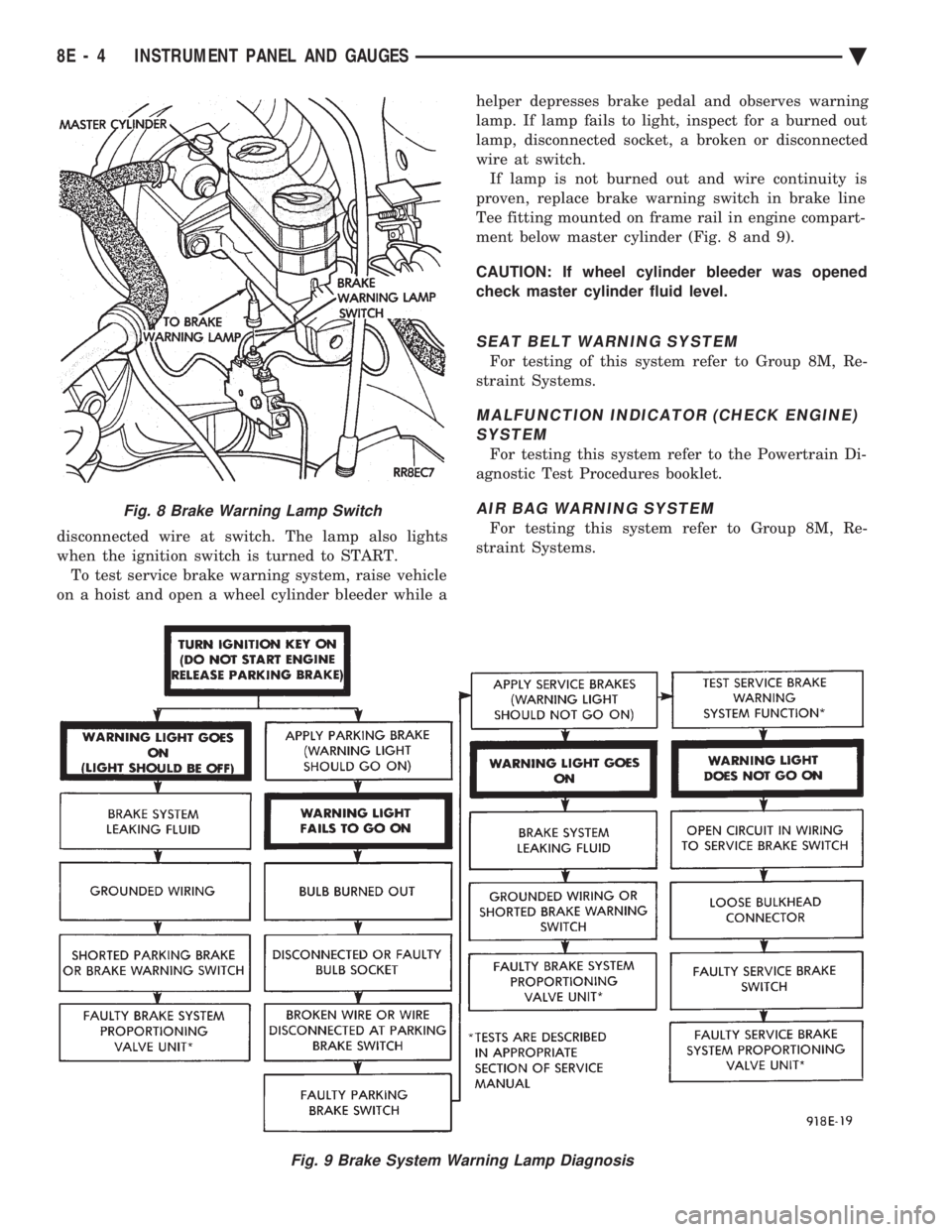
disconnected wire at switch. The lamp also lights
when the ignition switch is turned to START.To test service brake warning system, raise vehicle
on a hoist and open a wheel cylinder bleeder while a helper depresses brake pedal and observes warning
lamp. If lamp fails to light, inspect for a burned out
lamp, disconnected socket, a broken or disconnected
wire at switch. If lamp is not burned out and wire continuity is
proven, replace brake warning switch in brake line
Tee fitting mounted on frame rail in engine compart-
ment below master cylinder (Fig. 8 and 9).
CAUTION: If wheel cylinder bleeder was opened
check master cylinder fluid level.
SEAT BELT WARNING SYSTEM
For testing of this system refer to Group 8M, Re-
straint Systems.
MALFUNCTION INDICATOR (CHECK ENGINE) SYSTEM
For testing this system refer to the Powertrain Di-
agnostic Test Procedures booklet.
AIR BAG WARNING SYSTEM
For testing this system refer to Group 8M, Re-
straint Systems.
Fig. 8 Brake Warning Lamp Switch
Fig. 9 Brake System Warning Lamp Diagnosis
8E - 4 INSTRUMENT PANEL AND GAUGES Ä
Page 517 of 2438
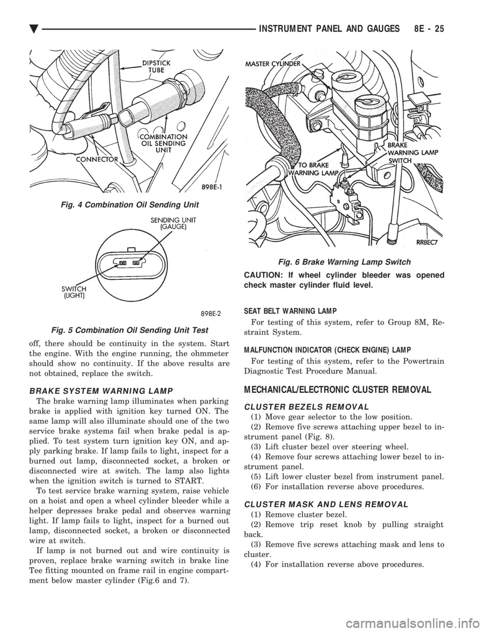
off, there should be continuity in the system. Start
the engine. With the engine running, the ohmmeter
should show no continuity. If the above results are
not obtained, replace the switch.
BRAKE SYSTEM WARNING LAMP
The brake warning lamp illuminates when parking
brake is applied with ignition key turned ON. The
same lamp will also illuminate should one of the two
service brake systems fail when brake pedal is ap-
plied. To test system turn ignition key ON, and ap-
ply parking brake. If lamp fails to light, inspect for a
burned out lamp, disconnected socket, a broken or
disconnected wire at switch. The lamp also lights
when the ignition switch is turned to START. To test service brake warning system, raise vehicle
on a hoist and open a wheel cylinder bleeder while a
helper depresses brake pedal and observes warning
light. If lamp fails to light, inspect for a burned out
lamp, disconnected socket, a broken or disconnected
wire at switch. If lamp is not burned out and wire continuity is
proven, replace brake warning switch in brake line
Tee fitting mounted on frame rail in engine compart-
ment below master cylinder (Fig.6 and 7). CAUTION: If wheel cylinder bleeder was opened
check master cylinder fluid level.
SEAT BELT WARNING LAMP
For testing of this system, refer to Group 8M, Re-
straint System.
MALFUNCTION INDICATOR (CHECK ENGINE) LAMP
For testing of this system, refer to the Powertrain
Diagnostic Test Procedure Manual.
MECHANICAL/ELECTRONIC CLUSTER REMOVAL
CLUSTER BEZELS REMOVAL
(1) Move gear selector to the low position.
(2) Remove five screws attaching upper bezel to in-
strument panel (Fig. 8). (3) Lift cluster bezel over steering wheel.
(4) Remove four screws attaching lower bezel to in-
strument panel. (5) Lift lower cluster bezel from instrument panel.
(6) For installation reverse above procedures.
CLUSTER MASK AND LENS REMOVAL
(1) Remove cluster bezel.
(2) Remove trip reset knob by pulling straight
back. (3) Remove five screws attaching mask and lens to
cluster. (4) For installation reverse above procedures.
Fig. 4 Combination Oil Sending Unit
Fig. 5 Combination Oil Sending Unit Test
Fig. 6 Brake Warning Lamp Switch
Ä INSTRUMENT PANEL AND GAUGES 8E - 25
Page 539 of 2438
(3) With the ignition switch ON, an open (discon-
nected sending unit wire) causes the oil, fuel or tem-
perature gauge to read below low, empty or cold
indicators. (4) If steps 2 and 3 check OK, refer to the individ-
ual sending unit test procedures.
FUEL TANK SENDING UNIT TEST
Refer to Group 14, Fuel for test procedure.
CHECK GAUGES WARNING LAMP TESTS
The check gauges warning lamp will illuminated
when the ignition key is turned to the ON position.
The lamp will illuminate if the engine oil pressure
drops below a safe level. The check gauge lamp will
light for high engine temperature or for low voltage. To test the system turn ignition key to the ON po-
sition. If the lamp fails to light, inspect for a broken
or disconnected wire at the oil pressure combination
sending unit, which is located at the front of the en-
gine (Fig. 13). If the wire at the connector checks
good pull connector loose from the switch terminal
and with a jumper wire ground connector to the en-
gine. With the ignition key turned to the ON posi-
tion check the warning lamp. If lamp still fails to
light, inspect for a burned lamp. If lamp still fails to
light, inspect for a burned out lamp or disconnected
socket in the cluster.
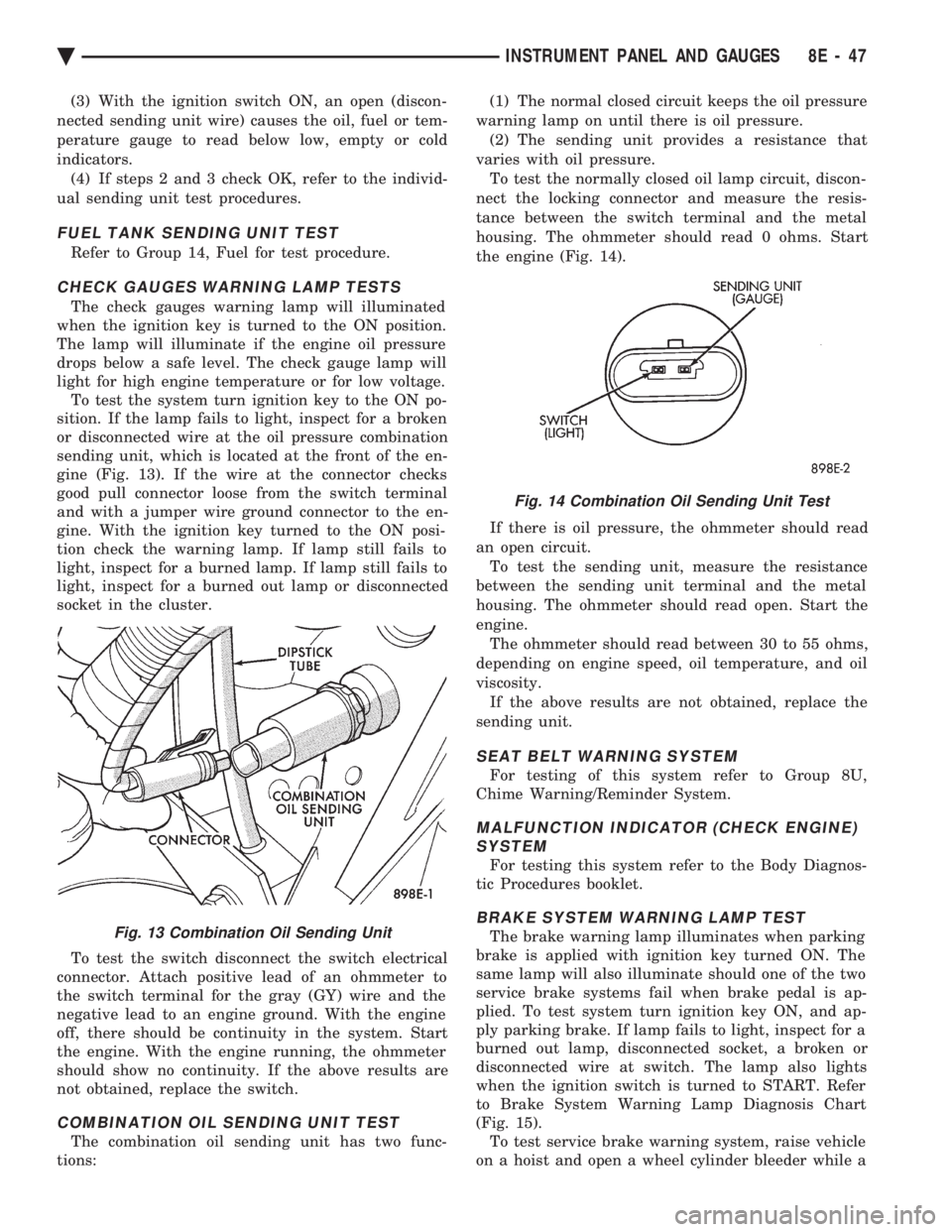
To test the switch disconnect the switch electrical
connector. Attach positive lead of an ohmmeter to
the switch terminal for the gray (GY) wire and the
negative lead to an engine ground. With the engine
off, there should be continuity in the system. Start
the engine. With the engine running, the ohmmeter
should show no continuity. If the above results are
not obtained, replace the switch.
COMBINATION OIL SENDING UNIT TEST
The combination oil sending unit has two func-
tions: (1) The normal closed circuit keeps the oil pressure
warning lamp on until there is oil pressure. (2) The sending unit provides a resistance that
varies with oil pressure. To test the normally closed oil lamp circuit, discon-
nect the locking connector and measure the resis-
tance between the switch terminal and the metal
housing. The ohmmeter should read 0 ohms. Start
the engine (Fig. 14).
If there is oil pressure, the ohmmeter should read
an open circuit. To test the sending unit, measure the resistance
between the sending unit terminal and the metal
housing. The ohmmeter should read open. Start the
engine. The ohmmeter should read between 30 to 55 ohms,
depending on engine speed, oil temperature, and oil
viscosity. If the above results are not obtained, replace the
sending unit.
SEAT BELT WARNING SYSTEM
For testing of this system refer to Group 8U,
Chime Warning/Reminder System.
MALFUNCTION INDICATOR (CHECK ENGINE) SYSTEM
For testing this system refer to the Body Diagnos-
tic Procedures booklet.
BRAKE SYSTEM WARNING LAMP TEST
The brake warning lamp illuminates when parking
brake is applied with ignition key turned ON. The
same lamp will also illuminate should one of the two
service brake systems fail when brake pedal is ap-
plied. To test system turn ignition key ON, and ap-
ply parking brake. If lamp fails to light, inspect for a
burned out lamp, disconnected socket, a broken or
disconnected wire at switch. The lamp also lights
when the ignition switch is turned to START. Refer
to Brake System Warning Lamp Diagnosis Chart
(Fig. 15). To test service brake warning system, raise vehicle
on a hoist and open a wheel cylinder bleeder while aFig. 13 Combination Oil Sending Unit
Fig. 14 Combination Oil Sending Unit Test
Ä INSTRUMENT PANEL AND GAUGES 8E - 47
Page 550 of 2438
AP BODY INDEX
page page
Cluster and Gauge Service and Testing ....... 58
Gauges ................................ 61
General Information ....................... 58 Instrument Panel Replacement
.............. 72
Interior Lamp Replacement ................. 73
Switch and Panel Component Service ......... 67
GENERAL INFORMATION
INSTRUMENT CLUSTER
There are two conventional instrument cluster as-
semblies available. The clusters incorporates mag-
netic type gauges and an electronically driven
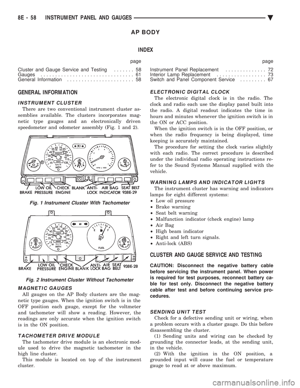
speedometer and odometer assembly (Fig. 1 and 2).
MAGNETIC GAUGES
All gauges on the AP Body clusters are the mag-
netic type gauges. When the ignition switch is in the
OFF position each gauge, except for the voltmeter
and tachometer will show a reading. However, the
readings are only accurate when the ignition switch
is in the ON position.
TACHOMETER DRIVE MODULE
The tachometer drive module is an electronic mod-
ule used to drive the magnetic tachometer in the
high line cluster. This module is located on top of the instrument
cluster.
ELECTRONIC DIGITAL CLOCK
The electronic digital clock is in the radio. The
clock and radio each use the display panel built into
the radio. A digital readout indicates the time in
hours and minutes whenever the ignition switch is in
the ON or ACC position. When the ignition switch is in the OFF position, or
when the radio frequency is being displayed, time
keeping is accurately maintained. The procedure for setting the clock varies slightly
with each radio. The correct procedure is described
under the individual radio operating instructions re-
fer to the Sound Systems Manual supplied with the
vehicle.
WARNING LAMPS AND INDICATOR LIGHTS
The instrument cluster has warning and indicators
lamps for eight different systems:
² Low oil pressure
² Brake warning
² Seat belt warning
² Malfunction indicator (check engine) lamp
² Air Bag
² High beam indicator
² Right and left turn signals.
² Anti-lock (ABS)
CLUSTER AND GAUGE SERVICE AND TESTING
CAUTION: Disconnect the negative battery cable
before servicing the instrument panel. When power
is required for test purposes, reconnect battery ca-
ble for test only. Disconnect the negative battery
cable after test and before continuing service pro-
cedures.
SENDING UNIT TEST
Check for a defective sending unit or wiring, when
a problem occurs with a cluster gauge. Do this before
disassembling the cluster. (1) Sending units and wiring can be checked by
grounding the connector leads, at the sending unit,
in the vehicle. (2) With the ignition in the ON position, a
grounded input will cause the fuel or temperature
gauge to read at or above maximum.
Fig. 1 Instrument Cluster With Tachometer
Fig. 2 Instrument Cluster Without Tachometer
8E - 58 INSTRUMENT PANEL AND GAUGES Ä
Page 551 of 2438
FUEL TANK SENDING UNIT TEST
Refer to Group 14, Fuel for test procedures.
LOW OIL PRESSURE WARNING LAMP TEST
The low oil pressure warning lamp will illuminate
when the ignition key is turned to the ON position
without engine running. The lamp also illuminates
should the engine oil pressure drop below a safe oil
pressure level. To test the system turn ignition key to the ON po-
sition. If the lamp fails to light, inspect for a broken
or disconnected wire at the oil pressure combination
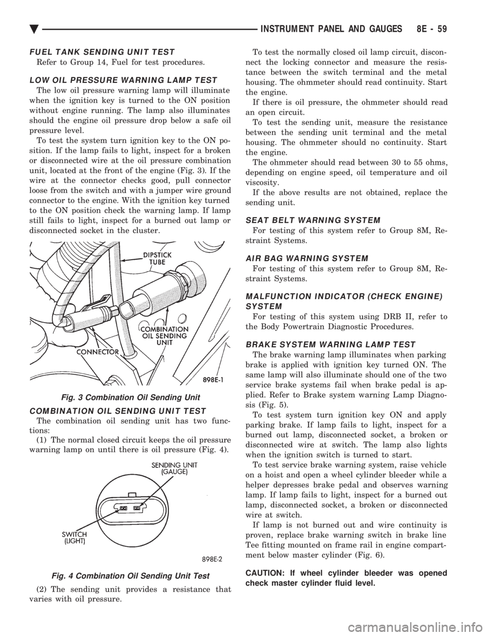
unit, located at the front of the engine (Fig. 3). If the
wire at the connector checks good, pull connector
loose from the switch and with a jumper wire ground
connector to the engine. With the ignition key turned
to the ON position check the warning lamp. If lamp
still fails to light, inspect for a burned out lamp or
disconnected socket in the cluster.
COMBINATION OIL SENDING UNIT TEST
The combination oil sending unit has two func-
tions: (1) The normal closed circuit keeps the oil pressure
warning lamp on until there is oil pressure (Fig. 4).
(2) The sending unit provides a resistance that
varies with oil pressure. To test the normally closed oil lamp circuit, discon-
nect the locking connector and measure the resis-
tance between the switch terminal and the metal
housing. The ohmmeter should read continuity. Start
the engine. If there is oil pressure, the ohmmeter should read
an open circuit. To test the sending unit, measure the resistance
between the sending unit terminal and the metal
housing. The ohmmeter should no continuity. Start
the engine. The ohmmeter should read between 30 to 55 ohms,
depending on engine speed, oil temperature and oil
viscosity. If the above results are not obtained, replace the
sending unit.
SEAT BELT WARNING SYSTEM
For testing of this system refer to Group 8M, Re-
straint Systems.
AIR BAG WARNING SYSTEM
For testing of this system refer to Group 8M, Re-
straint Systems.
MALFUNCTION INDICATOR (CHECK ENGINE) SYSTEM
For testing of this system using DRB II, refer to
the Body Powertrain Diagnostic Procedures.
BRAKE SYSTEM WARNING LAMP TEST
The brake warning lamp illuminates when parking
brake is applied with ignition key turned ON. The
same lamp will also illuminate should one of the two
service brake systems fail when brake pedal is ap-
plied. Refer to Brake system warning Lamp Diagno-
sis (Fig. 5). To test system turn ignition key ON and apply
parking brake. If lamp fails to light, inspect for a
burned out lamp, disconnected socket, a broken or
disconnected wire at switch. The lamp also lights
when the ignition switch is turned to start. To test service brake warning system, raise vehicle
on a hoist and open a wheel cylinder bleeder while a
helper depresses brake pedal and observes warning
lamp. If lamp fails to light, inspect for a burned out
lamp, disconnected socket, a broken or disconnected
wire at switch. If lamp is not burned out and wire continuity is
proven, replace brake warning switch in brake line
Tee fitting mounted on frame rail in engine compart-
ment below master cylinder (Fig. 6).
CAUTION: If wheel cylinder bleeder was opened
check master cylinder fluid level.
Fig. 3 Combination Oil Sending Unit
Fig. 4 Combination Oil Sending Unit Test
Ä INSTRUMENT PANEL AND GAUGES 8E - 59
Page 595 of 2438
² If no short to ground at connector, check speaker
resistance at amplifier connector for an reading of
three to five ohms.
² If resistance is OK, refer to Radio Diagnosis. If ra-
dio checks OK, replace amplifier.
² If resistance is less than three ohms check
speaker. Check across the speaker connector if less
than three ohms replace speaker. If resistance is OK
repair wires
CONDITION: MECHANICAL NOISE DISTORTION
² Check trim for loose parts and speaker attach-
ments for buzzes
² Remove speaker still connected and listen for dis-
tortion. Distortion replace speaker.
CONDITION: ONE SPEAKER NON-OPERATIVE
² Remove output signal connector from amplifier
and check for three to five ohms resistance to the
non-operative speaker. Refer to Fig. 34 for the appro-
priate pin numbers.
² If resistance is less than three ohms, test speaker
for resistance.
² If OK repair wire. If not replace speaker.
CONDITION: ALL SPEAKERS NON-OPERATIVE
²Check radio for being ON, are the display lights
on
² Radio not ON, refer to Radio Diagnosis
² Check Amplifier Connectors and wires for proper
connection
² Check pin 9 and pin 27 for battery voltage
² If voltage OK replace amplifier ²
If pin 27 has battery voltage and pin 9 has 0 volt-
age. Refer to Power Antenna Diagnosis and test volt-
age at antenna relay.
² If pin 9 has battery voltage and pin 27 has 0 volt-
age. Check pin 27 for short to ground.
² If shorted to ground repair wire
² If no short to ground check fuse cavity number 16
for blown fuse.
² If fuse blows again replace amplifier
RELAY/CHOKEÐINFINITY SPEAKER
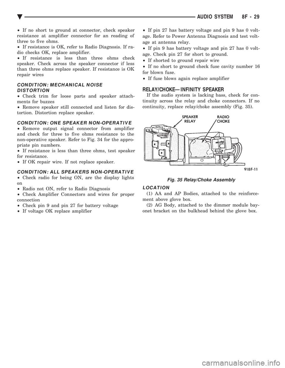
If the audio system is lacking bass, check for con-
tinuity across the relay and choke connectors. If no
continuity, replace relay/choke assembly (Fig. 35).
LOCATION
(1) AA and AP Bodies, attached to the reinforce-
ment above glove box. (2) AG Body, attached to the dimmer module bay-
onet bracket on the bulkhead behind the glove box.
Fig. 35 Relay/Choke Assembly
Ä AUDIO SYSTEM 8F - 29
Page 597 of 2438
HORNS
CONTENTS
page page
GENERAL INFORMATION .................. 1
HORN SWITCH REPLACEMENT ............ 3 TESTING HORN SYSTEM
................. 1
GENERAL INFORMATION
WARNING: ON VEHICLES EQUIPPED WITH AIR
BAG, SEE GROUP 8M, RESTRAINT SYSTEMS FOR
STEERING WHEEL OR COLUMN REMOVAL PROCE-
DURES.
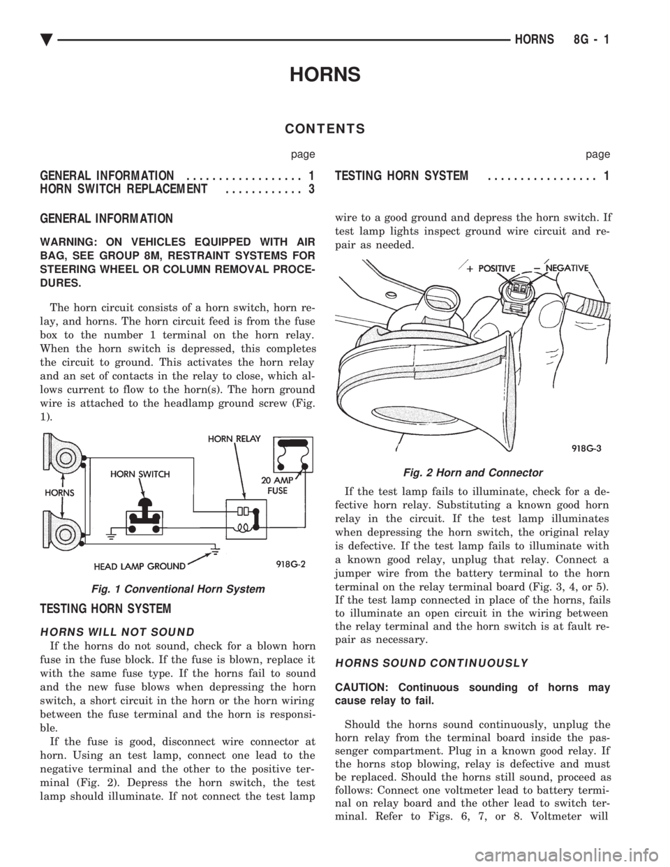
The horn circuit consists of a horn switch, horn re-
lay, and horns. The horn circuit feed is from the fuse
box to the number 1 terminal on the horn relay.
When the horn switch is depressed, this completes
the circuit to ground. This activates the horn relay
and an set of contacts in the relay to close, which al-
lows current to flow to the horn(s). The horn ground
wire is attached to the headlamp ground screw (Fig.
1).
TESTING HORN SYSTEM
HORNS WILL NOT SOUND
If the horns do not sound, check for a blown horn
fuse in the fuse block. If the fuse is blown, replace it
with the same fuse type. If the horns fail to sound
and the new fuse blows when depressing the horn
switch, a short circuit in the horn or the horn wiring
between the fuse terminal and the horn is responsi-
ble. If the fuse is good, disconnect wire connector at
horn. Using an test lamp, connect one lead to the
negative terminal and the other to the positive ter-
minal (Fig. 2). Depress the horn switch, the test
lamp should illuminate. If not connect the test lamp wire to a good ground and depress the horn switch. If
test lamp lights inspect ground wire circuit and re-
pair as needed.
If the test lamp fails to illuminate, check for a de-
fective horn relay. Substituting a known good horn
relay in the circuit. If the test lamp illuminates
when depressing the horn switch, the original relay
is defective. If the test lamp fails to illuminate with
a known good relay, unplug that relay. Connect a
jumper wire from the battery terminal to the horn
terminal on the relay terminal board (Fig. 3, 4, or 5).
If the test lamp connected in place of the horns, fails
to illuminate an open circuit in the wiring between
the relay terminal and the horn switch is at fault re-
pair as necessary.
HORNS SOUND CONTINUOUSLY
CAUTION: Continuous sounding of horns may
cause relay to fail.
Should the horns sound continuously, unplug the
horn relay from the terminal board inside the pas-
senger compartment. Plug in a known good relay. If
the horns stop blowing, relay is defective and must
be replaced. Should the horns still sound, proceed as
follows: Connect one voltmeter lead to battery termi-
nal on relay board and the other lead to switch ter-
minal. Refer to Figs. 6, 7, or 8. Voltmeter will
Fig. 1 Conventional Horn System
Fig. 2 Horn and Connector
Ä HORNS 8G - 1
Page 625 of 2438
CONDITION: MOTOR RUNS SLOWLY AT ALL SPEEDS
PROCEDURE
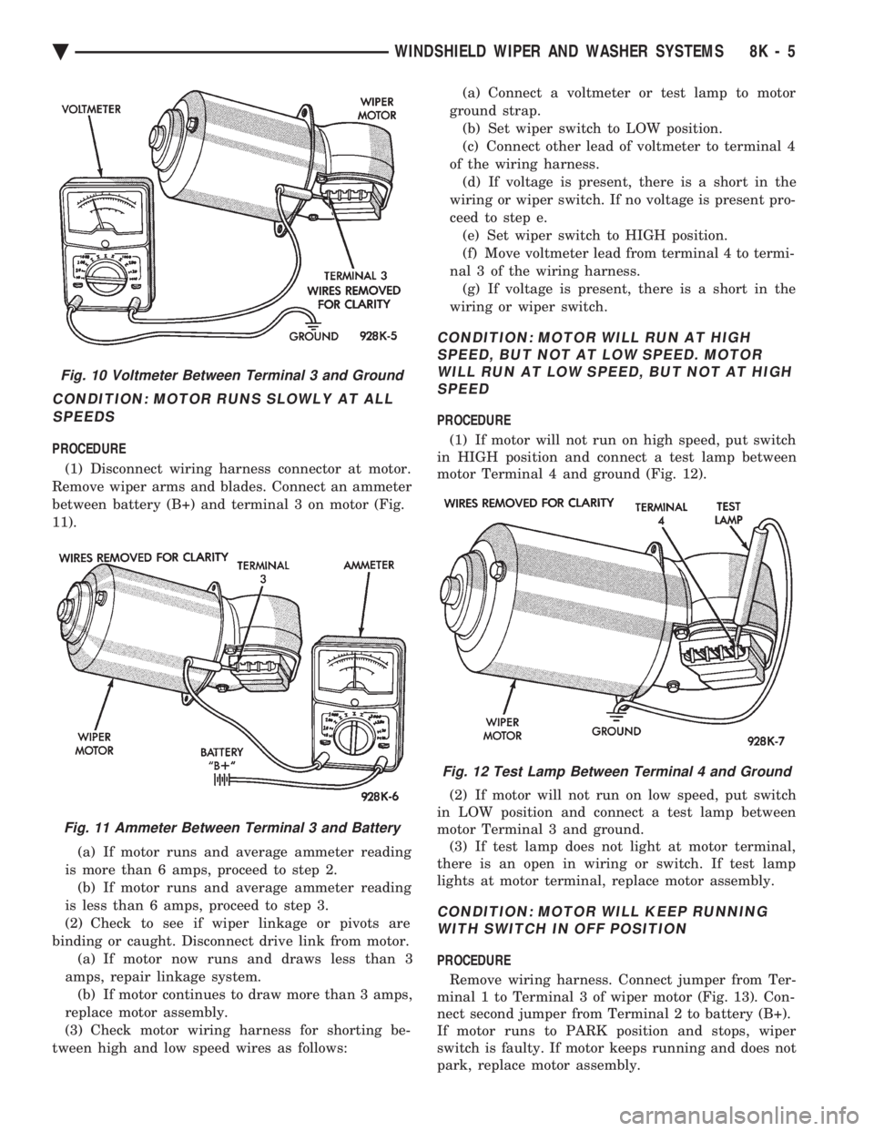
(1) Disconnect wiring harness connector at motor.
Remove wiper arms and blades. Connect an ammeter
between battery (B+) and terminal 3 on motor (Fig.
11).
(a) If motor runs and average ammeter reading
is more than 6 amps, proceed to step 2. (b) If motor runs and average ammeter reading
is less than 6 amps, proceed to step 3.
(2) Check to see if wiper linkage or pivots are
binding or caught. Disconnect drive link from motor. (a) If motor now runs and draws less than 3
amps, repair linkage system. (b) If motor continues to draw more than 3 amps,
replace motor assembly.
(3) Check motor wiring harness for shorting be-
tween high and low speed wires as follows: (a) Connect a voltmeter or test lamp to motor
ground strap. (b) Set wiper switch to LOW position.
(c) Connect other lead of voltmeter to terminal 4
of the wiring harness. (d) If voltage is present, there is a short in the
wiring or wiper switch. If no voltage is present pro-
ceed to step e. (e) Set wiper switch to HIGH position.
(f) Move voltmeter lead from terminal 4 to termi-
nal 3 of the wiring harness. (g) If voltage is present, there is a short in the
wiring or wiper switch.
CONDITION: MOTOR WILL RUN AT HIGH SPEED, BUT NOT AT LOW SPEED. MOTORWILL RUN AT LOW SPEED, BUT NOT AT HIGHSPEED
PROCEDURE
(1) If motor will not run on high speed, put switch
in HIGH position and connect a test lamp between
motor Terminal 4 and ground (Fig. 12).
(2) If motor will not run on low speed, put switch
in LOW position and connect a test lamp between
motor Terminal 3 and ground. (3) If test lamp does not light at motor terminal,
there is an open in wiring or switch. If test lamp
lights at motor terminal, replace motor assembly.
CONDITION: MOTOR WILL KEEP RUNNING WITH SWITCH IN OFF POSITION
PROCEDURE
Remove wiring harness. Connect jumper from Ter-
minal 1 to Terminal 3 of wiper motor (Fig. 13). Con-
nect second jumper from Terminal 2 to battery (B+).
If motor runs to PARK position and stops, wiper
switch is faulty. If motor keeps running and does not
park, replace motor assembly.
Fig. 10 Voltmeter Between Terminal 3 and Ground
Fig. 11 Ammeter Between Terminal 3 and Battery
Fig. 12 Test Lamp Between Terminal 4 and Ground
Ä WINDSHIELD WIPER AND WASHER SYSTEMS 8K - 5
Page 669 of 2438
CONCEALED HEADLAMPS INDEX
page page
Concealed Headlamp MotorÐAC-Body ........ 29
Diagnostic Procedures ..................... 27
General Information ....................... 27 Headlamp DoorÐAC-Body
................. 29
Headlamp DoorÐAY Body ................. 29
Headlamp Drive MotorÐAY Body ............ 30
GENERAL INFORMATION
For proper operation of the Concealed Headlamp
System, refer to the Owner's Manual provided with
the vehicle.
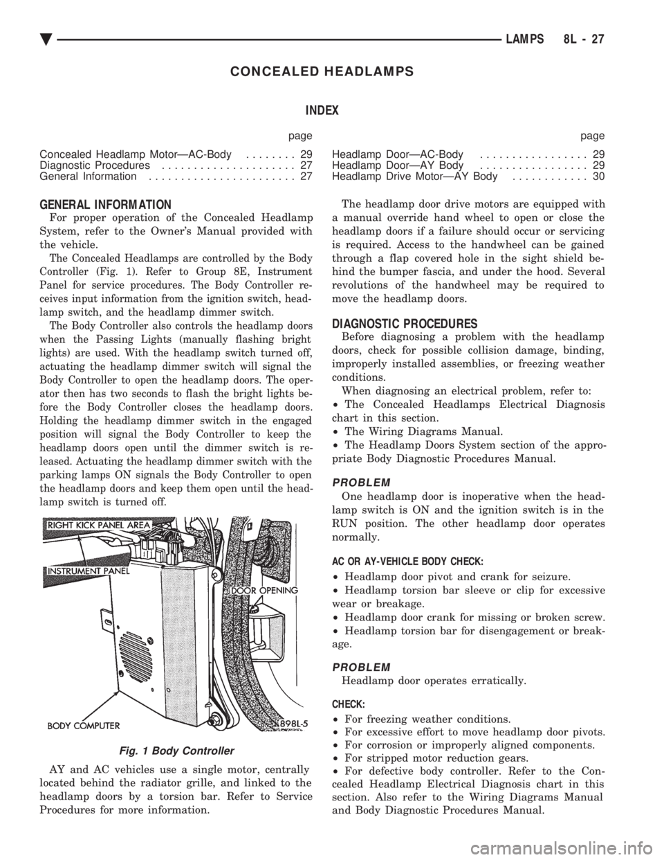
The Concealed Headlamps are controlled by the Body
Controller (Fig. 1). Refer to Group 8E, Instrument
Panel for service procedures. The Body Controller re-
ceives input information from the ignition switch, head-
lamp switch, and the headlamp dimmer switch. The Body Controller also controls the headlamp doors
when the Passing Lights (manually flashing bright
lights) are used. With the headlamp switch turned off,
actuating the headlamp dimmer switch will signal the
Body Controller to open the headlamp doors. The oper-
ator then has two seconds to flash the bright lights be-
fore the Body Controller closes the headlamp doors.
Holding the headlamp dimmer switch in the engaged
position will signal the Body Controller to keep the
headlamp doors open until the dimmer switch is re-
leased. Actuating the headlamp dimmer switch with the
parking lamps ON signals the Body Controller to open
the headlamp doors and keep them open until the head-
lamp switch is turned off.
AY and AC vehicles use a single motor, centrally
located behind the radiator grille, and linked to the
headlamp doors by a torsion bar. Refer to Service
Procedures for more information. The headlamp door drive motors are equipped with
a manual override hand wheel to open or close the
headlamp doors if a failure should occur or servicing
is required. Access to the handwheel can be gained
through a flap covered hole in the sight shield be-
hind the bumper fascia, and under the hood. Several
revolutions of the handwheel may be required to
move the headlamp doors.
DIAGNOSTIC PROCEDURES
Before diagnosing a problem with the headlamp
doors, check for possible collision damage, binding,
improperly installed assemblies, or freezing weather
conditions. When diagnosing an electrical problem, refer to:
² The Concealed Headlamps Electrical Diagnosis
chart in this section.
² The Wiring Diagrams Manual.
² The Headlamp Doors System section of the appro-
priate Body Diagnostic Procedures Manual.
PROBLEM
One headlamp door is inoperative when the head-
lamp switch is ON and the ignition switch is in the
RUN position. The other headlamp door operates
normally.
AC OR AY-VEHICLE BODY CHECK:
² Headlamp door pivot and crank for seizure.
² Headlamp torsion bar sleeve or clip for excessive
wear or breakage.
² Headlamp door crank for missing or broken screw.
² Headlamp torsion bar for disengagement or break-
age.
PROBLEM
Headlamp door operates erratically.
CHECK:
² For freezing weather conditions.
² For excessive effort to move headlamp door pivots.
² For corrosion or improperly aligned components.
² For stripped motor reduction gears.
² For defective body controller. Refer to the Con-
cealed Headlamp Electrical Diagnosis chart in this
section. Also refer to the Wiring Diagrams Manual
and Body Diagnostic Procedures Manual.
Fig. 1 Body Controller
Ä LAMPS 8L - 27
Page 685 of 2438
SERVICE OF DEPLOYED AIR BAG MODULE
After an air bag has been deployed, the air bag
module and clockspring must be replaced because
they cannot be reused. Other air bag system compo-
nents are replaced if damaged.
SCHEDULED MAINTENANCE INSPECTION
Vehicles equipped with a Air Bag System must be
inspected every three years or 30,000 miles / 48,000
Km. The following items should be inspected. (1) Inspect components for damage or deteriora-
tion. (a) If the air bag module housing shows signs of
physical damage or abuse, replace the module. (b) Check that both front impact sensors are
properly installed to the upper crossmember of the
radiator closure panel. Repair as required.
(2) Check the air bag warning lamp for proper op-
eration as follows: (a) Turn ignition switch to the ON position, the
air bag warning lamp should light. If not, test the system using the DRB II and Passive Restraint
System Diagnostic Procedures Manual. Repair as
required.
(b) The air bag warning lamp lights, but fails to go
out after ten seconds. Test the system using the DRB
II and Passive Restraint System Diagnostic Proce-
dures Manual. Repair as required. (c) Erasing of fault codes is not required.
AIR BAG SYSTEM CHECK
WARNING: BEFORE BEGINNING ANY AIR BAG SYS-
TEM CHECK PROCEDURES, REMOVE AND ISOLATE
THE BATTERY NEGATIVE (-) CABLE (GROUND)
FROM THE VEHICLE BATTERY. THIS IS THE ONLY
SURE WAY TO DISABLE THE AIR BAG SYSTEM.
FAILURE TO DO THIS COULD RESULT IN ACCIDEN-
TAL AIR BAG DEPLOYMENT AND POSSIBLE PER-
SONAL INJURY.
WHEN AN UNDEPLOYED AIR BAG ASSEMBLY IS
TO BE REMOVED FROM THE STEERING WHEEL,
DISCONNECT BATTERY GROUND CABLE AND
ISOLATE. ALLOW SYSTEM CAPACITOR TO DIS-
CHARGE FOR TWO MINUTES, THEN BEGIN AIR
BAG REMOVAL. (1) Disconnect the battery negative cable and iso-
late. (2) Remove forward console or cover as necessary.
(3) Connect DRB II to ASDM diagnostic 6-way con-
nector, located at right side of module. (4) Turn the ignition key to ON position. Exit vehicle
with DRB II. Use the latest version of the proper
cartridge. (5) After checking that no one is inside the vehicle,
connect the negative battery cable. (6) Using the DRB II, read and record active fault
data. (7) Read and record any stored faults.
(8) Refer to the Passive Restraint Diagnostic Test
Manual if any faults are found in steps 6 and 7. (9) Erase stored faults if there are no active fault
codes. If problems remain, fault codes will not erase. (10) With the ignition key in the ON position, make
sure no one is in the vehicle. (11) From the passenger side of vehicle, turn the
ignition key to OFF then ON and observe the instru-
ment cluster air bag lamp. It should go on for 6 to 8
seconds, then go out; indicating system is functioning
normally. If air bag warning lamp either fails to light,
blinks on and off or goes on and stays on, there is
a system malfunction. Refer to the Passive Re-
straint Diagnostic Test Manual to diagnose the
problem.
Fig. 3 Seal the Air Bag Exhaust Vents
Fig. 4 Vacuum Heater and A/C Outlets
Ä RESTRAINT SYSTEMS 8M - 3