check engine CHEVROLET DYNASTY 1993 Service Manual
[x] Cancel search | Manufacturer: CHEVROLET, Model Year: 1993, Model line: DYNASTY, Model: CHEVROLET DYNASTY 1993Pages: 2438, PDF Size: 74.98 MB
Page 44 of 2438
ENGINE INDEX
page page
Engine Oil Filter .......................... 9
Battery ................................ 15
Crankcase Ventilation System ............... 13
Drive Belts ............................. 14
Emission Control System ................... 14
Engine Air Cleaner ....................... 11
Engine Cooling System .................... 10 Engine Oil
............................... 8
Frequency of Engine Oil and Filter Changes ..... 8
Fuel Filter .............................. 14
Fuel Recommendations .................... 14
Ignition Cables, Distributor Cap, and Rotor ..... 14
Rubber and Plastic Component Inspection ...... 15
Spark Plugs ............................ 14
FREQUENCY OF ENGINE OIL AND FILTER
CHANGES
ENGINE OIL
Road conditions as well as your kind of driving af-
fect the interval at which your oil should be changed.
Check the following to determine if any apply to you:
² Frequent short trip driving less than 8 kilometers
(5 miles)
² Frequent driving in dusty conditions
² Frequent trailer towing
² Extensive idling (such as vehicle operation in stop
and go traffic)
² More than 50% of your driving is at sustained
high speeds during hot weather, above 32ÉC (90ÉF) If any of these apply to you then change your en-
gine oil every 4 800 kilometers (3,000 miles) or 3
months, whichever comes first. If none of these apply to you then change your oil
every 12 000 kilometers (7,500 miles) or 6 months,
whichever comes first. If none of these apply and the vehicle is in com-
mercial type service such as, Police, Taxi or Limou-
sine and principally used for highway driving of 40
kilometers (25 miles) or more between stations, the
engine oil should be changed every 8 000 kilometers
(5,000 miles) or 6 months, whichever comes first.
FLEXIBLE FUEL VEHICLES
Flexible fuel is corrosive and contributes to engine
oil contamination. When flexible fuel is being used,
the engine oil should be changed every 8 000 kilome-
ters (5,000 miles) or 6 months, whichever comes first.
OIL FILTER
The engine oil filter should be replaced with a new
filter at every second oil change.
ENGINE OIL
WARNING: NEW OR USED ENGINE OIL CAN BE IR-
RITATING TO THE SKIN. AVOID PROLONGED OR
REPEATED SKIN CONTACT WITH ENGINE OIL.
CONTAMINANTS IN USED ENGINE OIL, CAUSED
BY INTERNAL COMBUSTION, CAN BE HAZARDOUS TO YOUR HEALTH. THOROUGHLY WASH EX-
POSED SKIN WITH SOAP AND WATER. DO NOT WASH SKIN WITH GASOLINE, DIESEL
FUEL, THINNER, OR SOLVENTS, HEALTH PROB-
LEMS CAN RESULT. DO NOT POLLUTE, DISPOSE OF USED ENGINE
OIL PROPERLY. CONTACT YOUR DEALER OR
GOVERNMENT AGENCY FOR LOCATION OF COL-
LECTION CENTER IN YOUR AREA.
BREAK-IN PERIOD
CAUTION: Wide open throttle operation in low
gears, before engine break-in period is complete,
can damage engine.
On a Chrysler Corporation vehicle an extended
break-in period is not required. Driving speeds of not
over 80-90 km/h (50-55 mph) for the first 100 km (60
miles) is recommended. Hard acceleration and high
engine rpm in lower gears should be avoided.
SELECTING ENGINE OIL
CAUTION: Do not use non-detergent or straight
mineral oil when adding or changing crankcase lu-
bricant. Engine or Turbocharger failure can result.
The factory fill engine oil is a high quality, energy
conserving, crankcase lubricant. The Recommended
SAE Viscosity Grades chart defines the viscosity
grades that must be used based on temperature in
the region where vehicle is operated and optional
equipment.
NON-FLEXIBLE FUEL VEHICLES Chrysler Corporation recommends that Mopar mo-
tor oil, or equivalent, be used when adding or chang-
ing crankcase lubricant. The API symbol (Fig. 1) on
the container indicates the viscosity grade, quality
and fuel economy ratings of the lubricant it contains.
Use ENERGY CONSERVING II motor oil with API
SERVICE SG or SG/CD classification.
0 - 8 LUBRICATION AND MAINTENANCE Ä
Page 58 of 2438
BRAKE RESERVOIR LEVEL INSPECTION
WARNING: DO NOT ALLOW PETROLEUM OR WATER
BASE LIQUIDS TO CONTAMINATE BRAKE FLUID,
SEAL DAMAGE AND BRAKE FAILURE CAN RESULT.
RELIEVE PRESSURE IN ANTI-LOCK BRAKE SYS-
TEM BEFORE ADDING BRAKE FLUID TO RESER-
VOIR. IF NOT, BRAKE FLUID COULD DISCHARGED
FROM THE RESERVOIR POSSIBLY CAUSING PER-
SONAL INJURY.
The brake reservoir level should be inspected when
other under hood service is performed. It is normal
for the reservoir level to drop as disc brake pads
wear. When fluid must be added, use Mopar, Brake
Fluid or equivalent. Use only brake fluid conforming
to DOT 3, Federal, Department of Transportation
specification. To avoid brake fluid contamination, use
fluid from a properly sealed container. On vehicles with anti-lock brakes, depressurize the
system before inspecting fluid level. Turn OFF the
ignition and remove the key. Pump the brake pedal
at least 50 times to relieve the pressure in the sys-
tem.
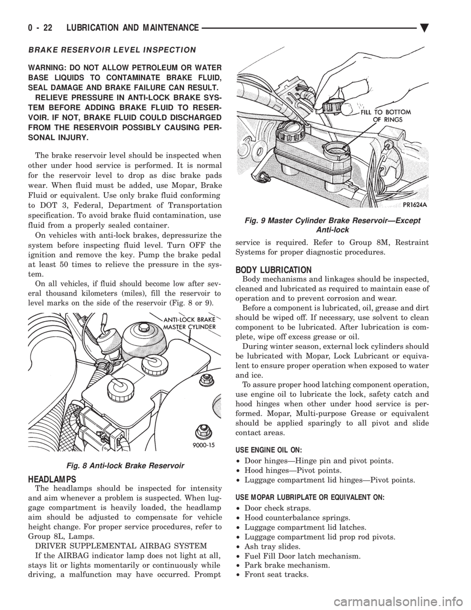
On all vehicles, if fluid should become low after sev-
eral thousand kilometers (miles), fill the reservoir to
level marks on the side of the reservoir (Fig. 8 or 9).
HEADLAMPS
The headlamps should be inspected for intensity
and aim whenever a problem is suspected. When lug-
gage compartment is heavily loaded, the headlamp
aim should be adjusted to compensate for vehicle
height change. For proper service procedures, refer to
Group 8L, Lamps. DRIVER SUPPLEMENTAL AIRBAG SYSTEM
If the AIRBAG indicator lamp does not light at all,
stays lit or lights momentarily or continuously while
driving, a malfunction may have occurred. Prompt service is required. Refer to Group 8M, Restraint
Systems for proper diagnostic procedures.
BODY LUBRICATION
Body mechanisms and linkages should be inspected,
cleaned and lubricated as required to maintain ease of
operation and to prevent corrosion and wear. Before a component is lubricated, oil, grease and dirt
should be wiped off. If necessary, use solvent to clean
component to be lubricated. After lubrication is com-
plete, wipe off excess grease or oil. During winter season, external lock cylinders should
be lubricated with Mopar, Lock Lubricant or equiva-
lent to ensure proper operation when exposed to water
and ice. To assure proper hood latching component operation,
use engine oil to lubricate the lock, safety catch and
hood hinges when other under hood service is per-
formed. Mopar, Multi-purpose Grease or equivalent
should be applied sparingly to all pivot and slide
contact areas.
USE ENGINE OIL ON:
² Door hingesÐHinge pin and pivot points.
² Hood hingesÐPivot points.
² Luggage compartment lid hingesÐPivot points.
USE MOPAR LUBRIPLATE OR EQUIVALENT ON:
² Door check straps.
² Hood counterbalance springs.
² Luggage compartment lid latches.
² Luggage compartment lid prop rod pivots.
² Ash tray slides.
² Fuel Fill Door latch mechanism.
² Park brake mechanism.
² Front seat tracks.
Fig. 8 Anti-lock Brake Reservoir
Fig. 9 Master Cylinder Brake ReservoirÐExcept
Anti-lock
0 - 22 LUBRICATION AND MAINTENANCE Ä
Page 99 of 2438
(8) Insert balls into raceway by tilting cage and in-
ner race assembly (Fig. 7). (9) Fasten boot to shaft. See Boots Install.
(10) On G.K.N. units insert the new circlip, pro-
vided with kit in shaft groove. Do not over expand
or twist circlip during assembly (Fig. 8). The S.S.G.
unit has a reusable circlip retainer that is an inte-
gral part of driver assembly.
(11) Position outer joint on splined end with hub
nut on stub shaft. Engage splines, and tap sharply
with mallet (Fig. 9). (12) Check that circlip is properly seated by at-
tempting to pull joint from the shaft. (13) Locate large end of boot over joint housing
checking that boot is not twisted. (14) Fasten boot to housing. See Boots Install.
INTERMEDIATE SHAFT ASSEMBLY RECONDITION
Reconditioning of intermediate shaft assembly (Fig.
1), for Equal Length Drive Shaft System vehicles is
the same for manual and automatic transaxles.
INTERMEDIATE SHAFT ASSEMBLY
REMOVE
(1) Remove right driveshaft. See Driveshaft As-
semblies Remove. (2) Remove speedometer pinion from the extension
housing (Fig. 2). (3) Remove the two bolts which mount the bearing
assembly bracket to the engine block (Fig. 1). (4) Remove assembly from transaxle extension by
pulling outward on the yoke (Fig. 3).
UNIVERSAL JOINT AND ROLLER
Disassemble
(1) Mark relationship of shaft to shaft to ensure
proper alignment at assembly. Apply penetrating oil
to bushings and remove snap rings. (2) Support yoke in vise and place a socket large
enough to receive bushing on top of yoke. A 1-1/8
inch socket is suitable (Fig. 4). (3) Striking socket with hammer will cause yoke to
move down and bushing to move up out of yoke into
socket. (4) After removing one bushing, turn parts in a
vise and remove other bushing in same manner.
Assemble (1) Hold cross in position between yoke ears with
one hand and start one bushing assembly into yoke
with other hand (Fig. 5). (2) Continue to hold cross in position, then ham-
mer bushing assembly into yoke and install snap
ring. (3) Install opposite bushing and snap ring in the
same manner.
Fig. 7 Inserting Balls into Raceway
Fig. 8 Installing New Circlip
Fig. 9 Position Joint onto Shaft Splines
Ä SUSPENSION AND DRIVESHAFTS 2 - 41
Page 107 of 2438
mount have been loosened for any reason, or if vehicle
has experienced front structural damage, driveshaft
lengths must be checked and corrected, if required. A
shorter than required driveshaft length can result in ob-
jectionable noise. A longer than required driveshaft
length may result in potential damage.
Use of the following procedure will ensure satisfac-
tory driveshaft engagement under all normal vehicle
operating conditions. (1) The vehicle must be completely assembled.
Front wheels must be properly aligned and in the
straight ahead position. The vehicle must be in a po-
sition so that the full weight of the body is distrib-
uted to all four tires. A platform hoist, or front end
alignment rack, is recommended.
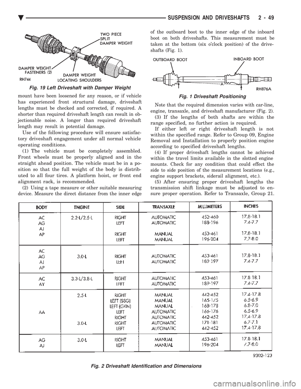
(2) Using a tape measure or other suitable measuring
device. Measure the direct distance from the inner edge of the outboard boot to the inner edge of the inboard
boot on both driveshafts. This measurement must be
taken at the bottom (six o'clock position) of the drive-
shafts (Fig. 1).
Note that the required dimension varies with car-line,
engine, transaxle, and driveshaft manufacturer (Fig. 2).
(3) If the lengths of both shafts are within the
range specified, no further action is required. If either left or right driveshaft length is not
within the specified range. Refer to Group 09, Engine
Removal and Installation to properly position engine
according to specified driveshaft lengths.
(4) If proper driveshaft lengths cannot be achieved
within the travel limits available in the slotted engine
mounts. Check for any condition that could effect the
side to side position of the measurement locations (e.g.,
engine support brackets, siderail alignment, etc.).
(5) After ensuring proper driveshaft lengths the
transmission shift linkage must be adjusted to en-
sure proper operation. Refer to Transaxle, Group 21.
Fig. 2 Driveshaft Identification and Dimensions
Fig. 19 Left Driveshaft with Damper Weight
Fig. 1 Driveshaft Positioning
Ä SUSPENSION AND DRIVESHAFTS 2 - 49
Page 136 of 2438
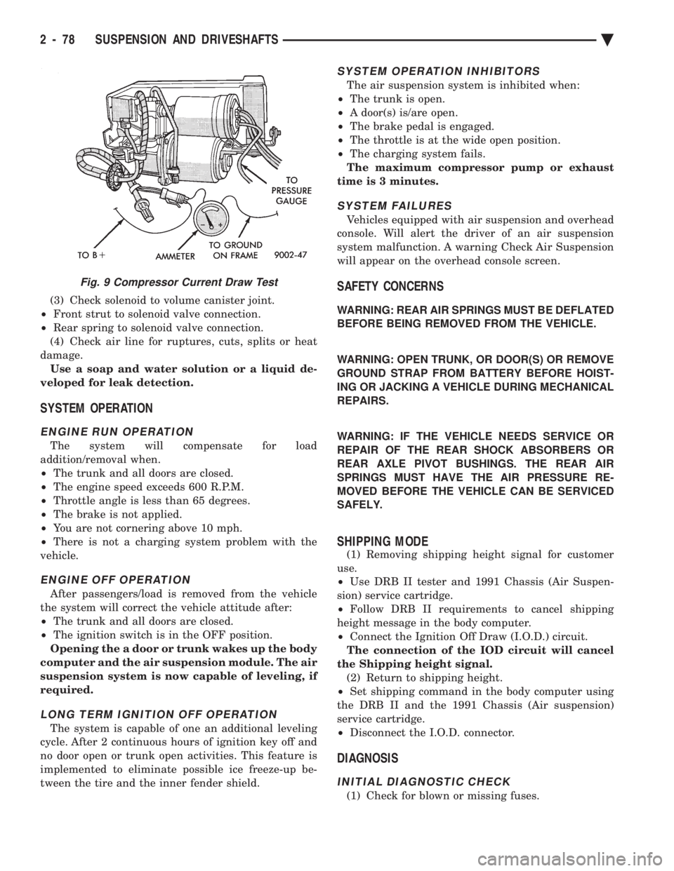
(3) Check solenoid to volume canister joint.
² Front strut to solenoid valve connection.
² Rear spring to solenoid valve connection.
(4) Check air line for ruptures, cuts, splits or heat
damage. Use a soap and water solution or a liquid de-
veloped for leak detection.
SYSTEM OPERATION
ENGINE RUN OPERATION
The system will compensate for load
addition/removal when.
² The trunk and all doors are closed.
² The engine speed exceeds 600 R.P.M.
² Throttle angle is less than 65 degrees.
² The brake is not applied.
² You are not cornering above 10 mph.
² There is not a charging system problem with the
vehicle.
ENGINE OFF OPERATION
After passengers/load is removed from the vehicle
the system will correct the vehicle attitude after:
² The trunk and all doors are closed.
² The ignition switch is in the OFF position.
Opening the a door or trunk wakes up the body
computer and the air suspension module. The air
suspension system is now capable of leveling, if
required.
LONG TERM IGNITION OFF OPERATION
The system is capable of one an additional leveling
cycle. After 2 continuous hours of ignition key off and
no door open or trunk open activities. This feature is
implemented to eliminate possible ice freeze-up be-
tween the tire and the inner fender shield.
SYSTEM OPERATION INHIBITORS
The air suspension system is inhibited when:
² The trunk is open.
² A door(s) is/are open.
² The brake pedal is engaged.
² The throttle is at the wide open position.
² The charging system fails.
The maximum compressor pump or exhaust
time is 3 minutes.
SYSTEM FAILURES
Vehicles equipped with air suspension and overhead
console. Will alert the driver of an air suspension
system malfunction. A warning Check Air Suspension
will appear on the overhead console screen.
SAFETY CONCERNS
WARNING: REAR AIR SPRINGS MUST BE DEFLATED
BEFORE BEING REMOVED FROM THE VEHICLE.
WARNING: OPEN TRUNK, OR DOOR(S) OR REMOVE
GROUND STRAP FROM BATTERY BEFORE HOIST-
ING OR JACKING A VEHICLE DURING MECHANICAL
REPAIRS.
WARNING: IF THE VEHICLE NEEDS SERVICE OR
REPAIR OF THE REAR SHOCK ABSORBERS OR
REAR AXLE PIVOT BUSHINGS. THE REAR AIR
SPRINGS MUST HAVE THE AIR PRESSURE RE-
MOVED BEFORE THE VEHICLE CAN BE SERVICED
SAFELY.
SHIPPING MODE
(1) Removing shipping height signal for customer
use.
² Use DRB II tester and 1991 Chassis (Air Suspen-
sion) service cartridge.
² Follow DRB II requirements to cancel shipping
height message in the body computer.
² Connect the Ignition Off Draw (I.O.D.) circuit.
The connection of the IOD circuit will cancel
the Shipping height signal. (2) Return to shipping height.
² Set shipping command in the body computer using
the DRB II and the 1991 Chassis (Air suspension)
service cartridge.
² Disconnect the I.O.D. connector.
DIAGNOSIS
INITIAL DIAGNOSTIC CHECK
(1) Check for blown or missing fuses.
Fig. 9 Compressor Current Draw Test
2 - 78 SUSPENSION AND DRIVESHAFTS Ä
Page 137 of 2438
(2) Check all connectors for correct assembly. Check
all connectors for incorrectly installed termi-
nals. (3) Check pin #21 for minimum of 9.5 volts.
(4) Check pin #20 for minimum of 9.5 volts (with
ignition key on). (5) Check voltage at pins #5 and #16. The measure-
ment should exceed 0 volts. (6) Check pin #19 for continuity.
(7) The engine speed should exceed 680 rpm during
idle. All doors and trunk must be closed for the
system to function.
DIAGNOSTICS PROCEDURES
(1) Use the D.R.B. II tester and the 1991 air suspen-
sion diagnostic service cartridge to begin the trouble-
shooting process. (2) Use the D.R.B. mating connector under the dash
(drivers side) to plug-in the D.R.B. II test connector
(Fig. 10). (3) The tester will conduct a complete check of the
suspension system status. (4) The tester will list the steps to follow to access
and diagnose the failure. (5) A Volt/Ohm meter can be used for some diagnos-
tic testing.
HEIGHT SENSOR CHECK
If a sensor signal/signals are missing. Follow the
repair procedure listed below. (1) Check ground circuit continuity. (Remember
front and rear grounds are on different circuits. (2) For front ground circuit continuity check circuit
S 33. (3) For rear ground circuit continuity check circuit
X20. (4) Refer to control module pin out chart and wiring
diagram (see Group 8F in wiring diagram manual) for
individual circuit details. (5) If open circuits are not found replace the compo-
nent. Complete circuit testing and connector assem-
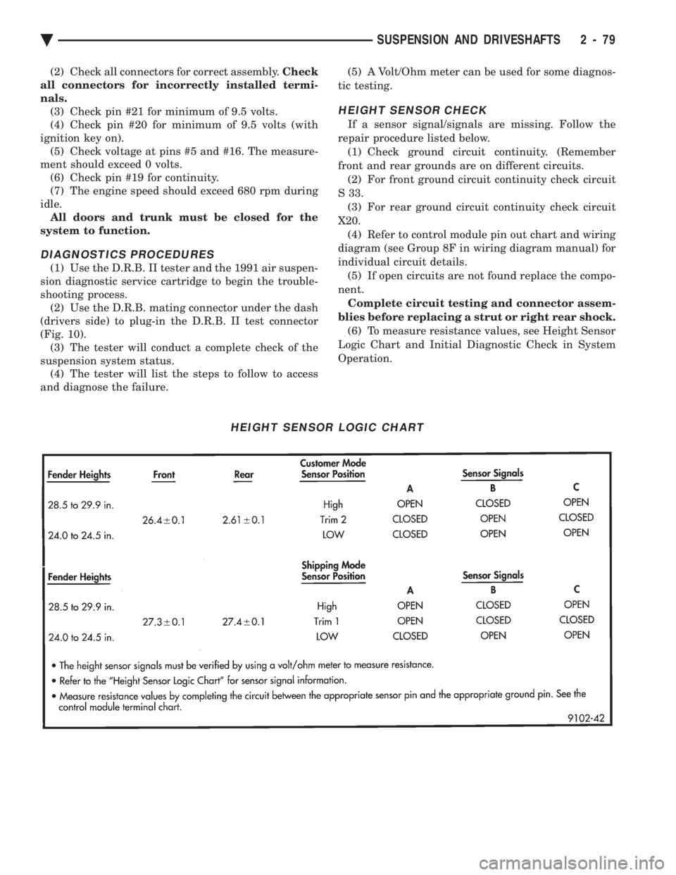
blies before replacing a strut or right rear shock. (6) To measure resistance values, see Height Sensor
Logic Chart and Initial Diagnostic Check in System
Operation.
HEIGHT SENSOR LOGIC CHART
Ä SUSPENSION AND DRIVESHAFTS 2 - 79
Page 216 of 2438
MASTER CYLINDER INDEX
page page
Brake Fluid Level Sensor .................. 66
General Information ....................... 66 Master Cylinder Service Procedures
.......... 67
Testing the Master Cylinder ................. 66
GENERAL INFORMATION
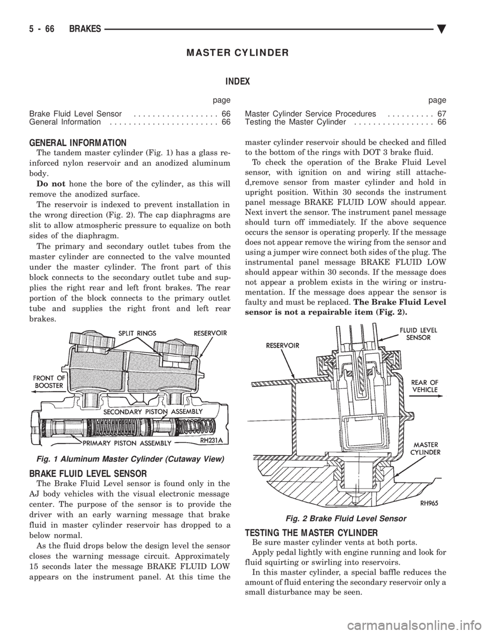
The tandem master cylinder (Fig. 1) has a glass re-
inforced nylon reservoir and an anodized aluminum
body. Do not hone the bore of the cylinder, as this will
remove the anodized surface. The reservoir is indexed to prevent installation in
the wrong direction (Fig. 2). The cap diaphragms are
slit to allow atmospheric pressure to equalize on both
sides of the diaphragm. The primary and secondary outlet tubes from the
master cylinder are connected to the valve mounted
under the master cylinder. The front part of this
block connects to the secondary outlet tube and sup-
plies the right rear and left front brakes. The rear
portion of the block connects to the primary outlet
tube and supplies the right front and left rear
brakes.
BRAKE FLUID LEVEL SENSOR
The Brake Fluid Level sensor is found only in the
AJ body vehicles with the visual electronic message
center. The purpose of the sensor is to provide the
driver with an early warning message that brake
fluid in master cylinder reservoir has dropped to a
below normal. As the fluid drops below the design level the sensor
closes the warning message circuit. Approximately
15 seconds later the message BRAKE FLUID LOW
appears on the instrument panel. At this time the master cylinder reservoir should be checked and filled
to the bottom of the rings with DOT 3 brake fluid. To check the operation of the Brake Fluid Level
sensor, with ignition on and wiring still attache-
d,remove sensor from master cylinder and hold in
upright position. Within 30 seconds the instrument
panel message BRAKE FLUID LOW should appear.
Next invert the sensor. The instrument panel message
should turn off immediately. If the above sequence
occurs the sensor is operating properly. If the message
does not appear remove the wiring from the sensor and
using a jumper wire connect both sides of the plug. The
instrumental panel message BRAKE FLUID LOW
should appear within 30 seconds. If the message does
not appear a problem exists in the wiring or instru-
mentation. If the message does appear the sensor is
faulty and must be replaced. The Brake Fluid Level
sensor is not a repairable item (Fig. 2).
TESTING THE MASTER CYLINDER
Be sure master cylinder vents at both ports.
Apply pedal lightly with engine running and look for
fluid squirting or swirling into reservoirs. In this master cylinder, a special baffle reduces the
amount of fluid entering the secondary reservoir only a
small disturbance may be seen.
Fig. 1 Aluminum Master Cylinder (Cutaway View)
Fig. 2 Brake Fluid Level Sensor
5 - 66 BRAKES Ä
Page 218 of 2438
INSTALLING MASTER CYLINDER
Position master cylinder over studs of power brake
unit, align push rod with master cylinder piston. Install the master cylinder to power brake unit
mounting nuts (Fig. 4) and tighten to 28 N Im (250 in.
lbs.) torque. Connect brake tubes to master cylinder primary and
secondary ports. Tighten fittings to 17 N Im (145 in-
.lbs.) torque.
POWER BRAKES
GENERAL INFORMATION
All vehicles, except non turbo charged AP bodies,
equipped with manual transmissions use a 205 mm
tandem booster. The non turbo charged manual trans-
mission equipped AP body application use a 230 mm
non-tandem booster. The purpose of the vacuum operated power brake
booster. Is to reduce the amount of force applied to the
brake pedal by the drivers foot. To obtain the required
hydraulic pressure in the brake system to stop the
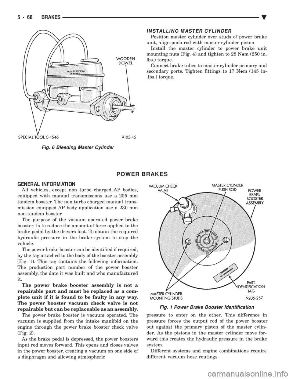
vehicle. The power brake booster can be identified if required,
by the tag attached to the body of the booster assembly
(Fig. 1). This tag contains the following information.
The production part number of the power booster
assembly, the date it was built and who manufactured
it. The power brake booster assembly is not a
repairable part and must be replaced as a com-
plete unit if it is found to be faulty in any way.
The power booster vacuum check valve is not
repairable but can be replaceable as an assembly. The power brake booster is vacuum operated. The
vacuum is supplied from the intake manifold on the
engine through the power brake booster check valve
(Fig. 2). As the brake pedal is depressed, the power boosters
input rod moves forward. This opens and closes valves
in the power booster, creating a vacuum on one side of
a diaphragm and allowing atmospheric pressure to enter on the other. This difference in
pressure forces the output rod of the power booster
out against the primary piston of the master cylin-
der. As the pistons in the master cylinder move for-
ward this creates the hydraulic pressure in the brake
system. Different systems and engine combinations require
different vacuum hose routings.
Fig. 6 Bleeding Master Cylinder
Fig. 1 Power Brake Booster Identification
5 - 68 BRAKES Ä
Page 219 of 2438
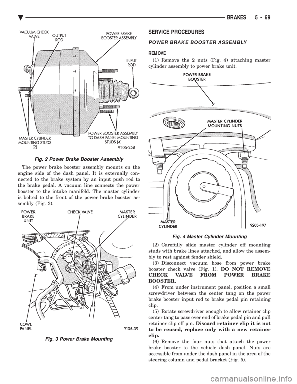
The power brake booster assembly mounts on the
engine side of the dash panel. It is externally con-
nected to the brake system by an input push rod to
the brake pedal. A vacuum line connects the power
booster to the intake manifold. The master cylinder
is bolted to the front of the power brake booster as-
sembly (Fig. 3).
SERVICE PROCEDURES
POWER BRAKE BOOSTER ASSEMBLY
REMOVE
(1) Remove the 2 nuts (Fig. 4) attaching master
cylinder assembly to power brake unit.
(2) Carefully slide master cylinder off mounting
studs with brake lines attached, and allow the assem-
bly to rest against fender shield. (3) Disconnect vacuum hose from power brake
booster check valve (Fig. 1). DO NOT REMOVE
CHECK VALVE FROM POWER BRAKE
BOOSTER. (4) From under instrument panel, position a small
screwdriver between the center tang on the power
brake booster input rod to brake pedal pin retaining
clip. (5) Rotate screwdriver enough to allow retainer clip
center tang to pass over end of brake pedal pin and pull
retainer clip off pin. Discard retainer clip it is not
to be reused, replace only with a new retainer
clip. (6) Remove the four nuts that attach the power
brake booster to the vehicle dash panel. Nuts are
accessible from under the dash panel in the area of the
steering column and pedal bracket (Fig. 5).
Fig. 2 Power Brake Booster Assembly
Fig. 3 Power Brake Mounting
Fig. 4 Master Cylinder Mounting
Ä BRAKES 5 - 69
Page 333 of 2438
MANUAL TRANSAXLE CLUTCH
CONTENTS
page page
CLEANING PRECAUTIONS ................. 6
CLUTCH CABLE MECHANISM .............. 1
CLUTCH CABLE REPLACEMENT ............ 2
CLUTCH CHATTER COMPLAINTS ........... 1
CLUTCH DISC REPLACEMENT ............. 5
CLUTCH PEDAL NOISE/POP ............... 2 CLUTCH PEDAL POSITION SWITCH
......... 4
EXCESSIVE CLUTCH SPIN TIME/CLASH INTO REVERSE COMPLAINTS ............ 1
GENERAL INFORMATION .................. 1
RELEASE BEARING AND FORK ............. 6
GENERAL INFORMATION
Throughout this group, references may be made to
a particular vehicle by letter or number designation.
A chart showing the breakdown of these designations
is included in the Introduction Section at the front of
this service manual. The clutch used in all models are a single, dry disc
type with no adjustment for wear being provided in
the clutch itself. The clutch pedal is connected to the release shaft
through a cable and lever. The upper end of the clutch pedal pivots in the
pedal bracket on two nylon bushings. These bushings
do not require periodic lubrication.
CLUTCH CHATTER COMPLAINTS
For all clutch chatter complaints, do the following:
(1) Check for loose, misaligned, or broken engine
and transmission mounts. If present, they should be
corrected at this time. Test vehicle for chatter. If
chatter is gone, there is no need to go any further. If
chatter persists: (2) Check to see if clutch cable routing is correct
and operates smoothly. (3) Check for loose connections in drive train. Cor-
rect any problems and determine if clutch chatter
complaints has been satisfied. If not, (4) Remove transaxle. See Group 21, Manual Tran-
saxle, for procedure. (5) Check to see if the release bearing is sticky or
binding. Replace bearing, if needed. (6) Check linkage for excessive wear on bushings.
Replace all worn parts. A small amount of bearing
grease between the release shaft bushings and the
shaft is beneficial, but not required. (7) Check flywheel and clutch pressure plate for
contamination (dirt, oil) or scored. Replace flywheel
and/or pressure plate, if required. (8) Check to see if the clutch disc hub splines are
damaged. Replace with new disc. (9) Check input shaft splines for damage. Replace
if necessary. (10) Check for uneven wear on clutch fingers.
EXCESSIVE CLUTCH SPIN TIME/CLASH INTO
REVERSE COMPLAINTS
For all excessive clutch spin time/clash into reverse
complaints, do the following: (1) Depress clutch pedal to floor and hold. After
three seconds, shift to reverse. If clash is present,
clutch has excessive spin time. (2) Remove transaxle. See Group 21, Manual Tran-
saxle, for procedure. (3) Check the input shaft spline, clutch disc splines
and release bearing for dry rust. If present, clean
rust off and apply a light coat of bearing grease to
the input shaft splines. Apply grease on the input
shaft splines only where the clutch disc slides. (4) Check to see if the clutch disc hub splines are
damaged, replace with new disc if required. (5) Check the input shaft for damaged splines. Re-
place as necessary. (6) Check for excessive clutch disc runout or
warpage. (7) Install clutch assembly and transaxle.
CLUTCH CABLE MECHANISM
The manual transaxle clutch release system has a
unique self-adjusting mechanism to compensate for
clutch disc wear. This adjuster mechanism is located
within the clutch pedal. The preload spring main-
tains tension on the cable. This tension keeps the
clutch release bearing continuously loaded against
the fingers of the clutch cover assembly. When the pedal is depressed, teeth on the adjuster
and the positioner engage and pull the release cable.
A spring located behind the adjuster ensures proper
tooth engagement. When the pedal is released, the adjuster contacts
the bumper. This separates the adjuster and posi-
tioner teeth, allowing the preload spring to function.
Ä MANUAL TRANSAXLE CLUTCH 6 - 1