water pump CHEVROLET DYNASTY 1993 Owner's Manual
[x] Cancel search | Manufacturer: CHEVROLET, Model Year: 1993, Model line: DYNASTY, Model: CHEVROLET DYNASTY 1993Pages: 2438, PDF Size: 74.98 MB
Page 1576 of 2438
shaft end play. A sintered iron (TBI engine and steel
billet Turbo III engines) timing belt sprocket is
mounted on the cam nose, and a hydrodynamic oil
seal is used for oil control at the front of the cam-
shaft. ACCESSORY SHAFT: The iron accessory shaft
has two bearing journals and is housed in the for-
ward facing side of the block. A hydrodynamic seal,
installed in an aluminum housing attached to the
block, provides retention, shaft thrust, and oil con-
trol. The accessory shaft is driven by the timing belt
through a sintered iron (TBI engine and steel billet
Turbo III engines) sprocket mounted on the nose of
the accessory shaft. The accessory shaft in turn
drives the oil pump and distributor on 2.2/2.5L and
2.5L FFV and the oil pump only on Turbo III. VALVES: The valves are actuated by roller cam
followers which pivot on stationary hydraulic lash
adjusters. The valve train with 40.6 mm (1.60 inch)
diameter intake valves and 35.4 mm (1.39 inch) di-
ameter exhaust valves employ viton rubber valve
stem seals except 2.5L FFv . the 2.5L FFV valve
stem seals are made of special rubber compound
which resist the deteriorating effects of methanol
fuel by-products that enter the oil during combus-
tion. Valve springs, spring retainers, and locks are
conventional. For Turbo III engines the valves are
actuated by roller tipped rocker arms with hydraulic
lash adjusters which pivot on a shaft. The valve train
with 33.88 mm (1.33 in.) diameter intake valves are
arranged in line opposite of the 29.26 mm (1.15 in.)
diameter exhaust valves employ locking valve stem
seals. Valve springs, spring retainers, and locks are
not interchangeable with other engines. BALANCE SHAFTS: 2.2 Turbo III and 2.5L en-
gines are equipped with two counter rotating balance
shafts installed in a carrier attached to the lower
crankcase. The shafts are interconnect through
gears. These gears are driven by a short chain from
the crankshaft, to rotate at two times crankshaft
speed. This counterbalances certain engine recipro-
cating forces. INTAKE MANIFOLDS:
All intake manifolds are
aluminum castings, attached to the cylinder head
with eight bolts. N.A. engines use a four branch de-
sign. This long branch fan design enhances low and
midspeed torque. It also features an integrally cast
water crossover passage to warm incoming fuel/air
mixture, plus an EGR mounting boss and PCV inlet. The Turbo III engine intake manifold is a log type
with tuned runners. The manifold is machined to ac-
cept fuel injectors near the ports of each cylinder. EXHAUST MANIFOLDS: The exhaust manifolds
are made of nodular cast iron for strength and high
temperatures. All naturally aspirated (N.A.) and tur-
bocharged engines exit exhaust gasses through a ma-
chined, articulated joint connection to the exhaust
pipe. 2.2/2.5L and 2.5L FFV manifolds intermesh
with the intake manifold at the cylinder head. N.A. engines use a four branch design with cylin-
ders one and four joined and cylinder two and three
joined to exit at the outlet. The Turbo III engine exhaust manifold also carries
the turbocharger. This manifold has a modified log
type collector with exhaust gasses directed to and
through the turbocharger to exit the conical (articu-
lated joint) outlet machined into the turbocharger ex-
haust elbow. ENGINE LUBRICATION: Refer to Group 0 Lu-
brication and Maintenance for recommended oil to be
used in various engine application. System is full
flow filtration, pressure feed type. The oil pump is
mounted within the crankcase and driven by the ac-
cessory shaft. Pressurized oil is then routed through
the main oil gallery, running the length of the cylin-
der block, supplying main and rod bearings with fur-
ther routing (for 2.2L turbo III and 2.5L engines) to
the lower balance shaft assemblies. Pistons are lubri-
cated from directed holes in the connecting rod as-
semblies. Camshaft and valve mechanisms are
lubricated from a full-length cylinder head oil gallery
supplied from the crankcase main oil gallery.
9 - 10 2.2/2.5L ENGINE Ä
Page 1584 of 2438
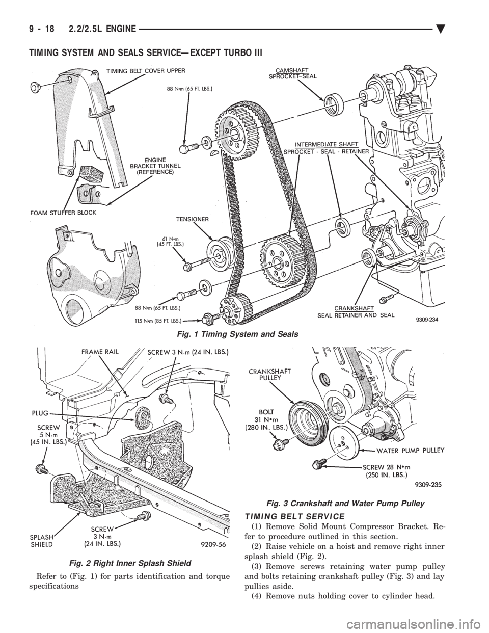
TIMING SYSTEM AND SEALS SERVICEÐEXCEPT TURBO III
Refer to (Fig. 1) for parts identification and torque
specifications
TIMING BELT SERVICE
(1) Remove Solid Mount Compressor Bracket. Re-
fer to procedure outlined in this section. (2) Raise vehicle on a hoist and remove right inner
splash shield (Fig. 2). (3) Remove screws retaining water pump pulley
and bolts retaining crankshaft pulley (Fig. 3) and lay
pullies aside. (4) Remove nuts holding cover to cylinder head.
Fig. 2 Right Inner Splash Shield
Fig. 3 Crankshaft and Water Pump Pulley
Fig. 1 Timing System and Seals
9 - 18 2.2/2.5L ENGINE Ä
Page 1592 of 2438
valve spring retainer locks to become dislocated
when depressing the valve spring. Check and make
sure the locks are in their proper location. (3) Install valve cover as previously outlined in
this section.
VALVE SPRINGS AND VALVE STEM SEALS
REMOVAL
(1) Remove rocker arms as previously outlined in
this section. (2) Rotate crankshaft until piston is at TDC on
compression. (3) With air hose attached to adapter tool installed
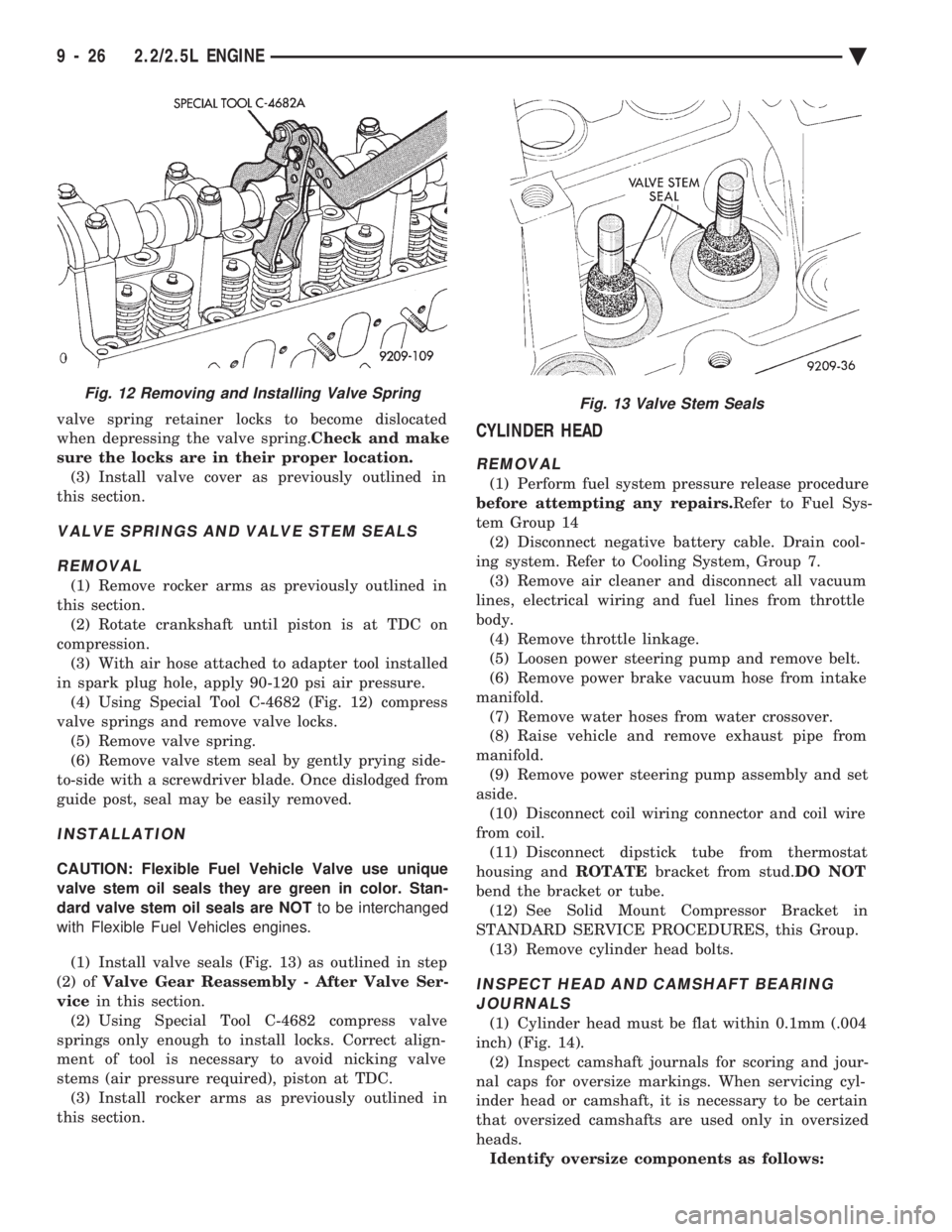
in spark plug hole, apply 90-120 psi air pressure. (4) Using Special Tool C-4682 (Fig. 12) compress
valve springs and remove valve locks. (5) Remove valve spring.
(6) Remove valve stem seal by gently prying side-
to-side with a screwdriver blade. Once dislodged from
guide post, seal may be easily removed.
INSTALLATION
CAUTION: Flexible Fuel Vehicle Valve use unique
valve stem oil seals they are green in color. Stan-
dard valve stem oil seals are NOT to be interchanged
with Flexible Fuel Vehicles engines.
(1) Install valve seals (Fig. 13) as outlined in step
(2) of Valve Gear Reassembly - After Valve Ser-
vice in this section.
(2) Using Special Tool C-4682 compress valve
springs only enough to install locks. Correct align-
ment of tool is necessary to avoid nicking valve
stems (air pressure required), piston at TDC. (3) Install rocker arms as previously outlined in
this section.
CYLINDER HEAD
REMOVAL
(1) Perform fuel system pressure release procedure
before attempting any repairs. Refer to Fuel Sys-
tem Group 14 (2) Disconnect negative battery cable. Drain cool-
ing system. Refer to Cooling System, Group 7. (3) Remove air cleaner and disconnect all vacuum
lines, electrical wiring and fuel lines from throttle
body. (4) Remove throttle linkage.
(5) Loosen power steering pump and remove belt.
(6) Remove power brake vacuum hose from intake
manifold. (7) Remove water hoses from water crossover.
(8) Raise vehicle and remove exhaust pipe from
manifold. (9) Remove power steering pump assembly and set
aside. (10) Disconnect coil wiring connector and coil wire
from coil. (11) Disconnect dipstick tube from thermostat
housing and ROTATEbracket from stud. DO NOT
bend the bracket or tube. (12) See Solid Mount Compressor Bracket in
STANDARD SERVICE PROCEDURES, this Group. (13) Remove cylinder head bolts.
INSPECT HEAD AND CAMSHAFT BEARINGJOURNALS
(1) Cylinder head must be flat within 0.1mm (.004
inch) (Fig. 14). (2) Inspect camshaft journals for scoring and jour-
nal caps for oversize markings. When servicing cyl-
inder head or camshaft, it is necessary to be certain
that oversized camshafts are used only in oversized
heads. Identify oversize components as follows:
Fig. 12 Removing and Installing Valve SpringFig. 13 Valve Stem Seals
9 - 26 2.2/2.5L ENGINE Ä
Page 1598 of 2438
Before installing the bolts, the threads should be
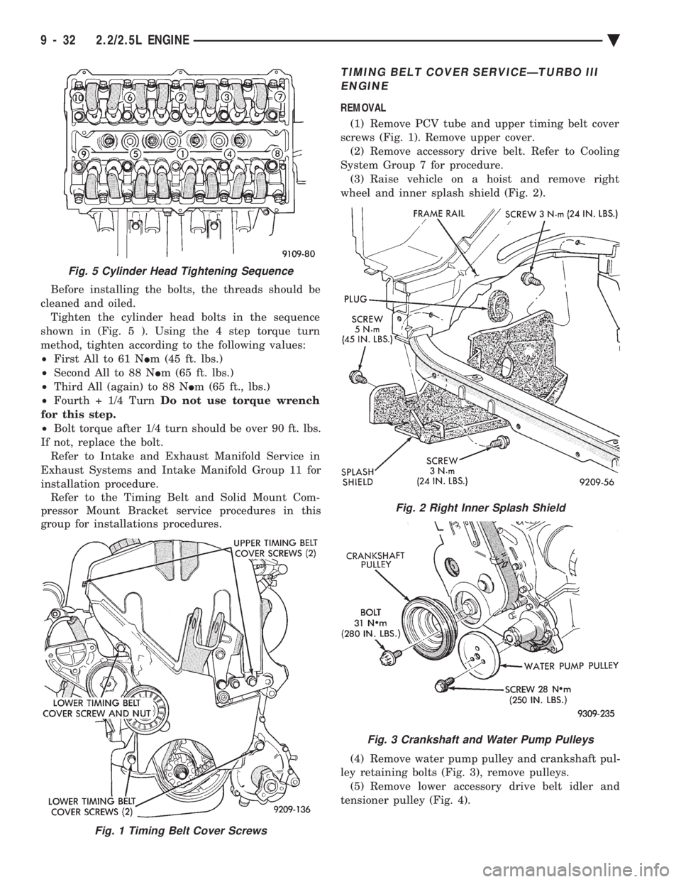
cleaned and oiled. Tighten the cylinder head bolts in the sequence
shown in (Fig. 5 ). Using the 4 step torque turn
method, tighten according to the following values:
² First All to 61 N Im (45 ft. lbs.)
² Second All to 88 N Im (65 ft. lbs.)
² Third All (again) to 88 N Im (65 ft., lbs.)
² Fourth + 1/4 Turn Do not use torque wrench
for this step.
² Bolt torque after 1/4 turn should be over 90 ft. lbs.
If not, replace the bolt. Refer to Intake and Exhaust Manifold Service in
Exhaust Systems and Intake Manifold Group 11 for
installation procedure. Refer to the Timing Belt and Solid Mount Com-
pressor Mount Bracket service procedures in this
group for installations procedures.
TIMING BELT COVER SERVICEÐTURBO III
ENGINE
REMOVAL
(1) Remove PCV tube and upper timing belt cover
screws (Fig. 1). Remove upper cover. (2) Remove accessory drive belt. Refer to Cooling
System Group 7 for procedure. (3) Raise vehicle on a hoist and remove right
wheel and inner splash shield (Fig. 2).
(4) Remove water pump pulley and crankshaft pul-
ley retaining bolts (Fig. 3), remove pulleys. (5) Remove lower accessory drive belt idler and
tensioner pulley (Fig. 4).
Fig. 1 Timing Belt Cover Screws
Fig. 5 Cylinder Head Tightening Sequence
Fig. 2 Right Inner Splash Shield
Fig. 3 Crankshaft and Water Pump Pulleys
9 - 32 2.2/2.5L ENGINE Ä
Page 1599 of 2438
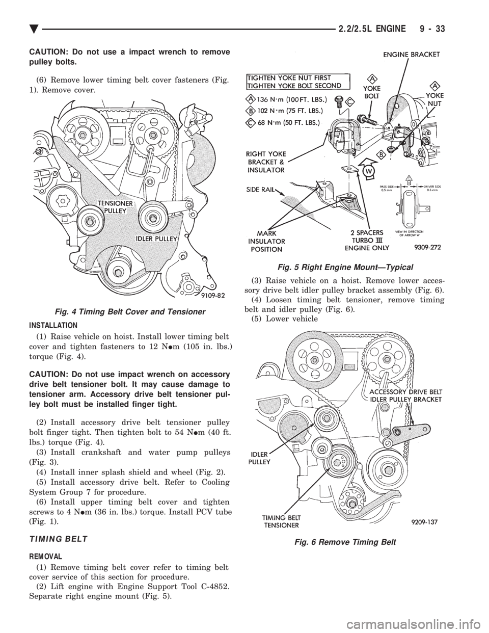
CAUTION: Do not use a impact wrench to remove
pulley bolts. (6) Remove lower timing belt cover fasteners (Fig.
1). Remove cover.
INSTALLATION (1) Raise vehicle on hoist. Install lower timing belt
cover and tighten fasteners to 12 N Im (105 in. lbs.)
torque (Fig. 4).
CAUTION: Do not use impact wrench on accessory
drive belt tensioner bolt. It may cause damage to
tensioner arm. Accessory drive belt tensioner pul-
ley bolt must be installed finger tight. (2) Install accessory drive belt tensioner pulley
bolt finger tight. Then tighten bolt to 54 N Im (40 ft.
lbs.) torque (Fig. 4). (3) Install crankshaft and water pump pulleys
(Fig. 3). (4) Install inner splash shield and wheel (Fig. 2).
(5) Install accessory drive belt. Refer to Cooling
System Group 7 for procedure. (6) Install upper timing belt cover and tighten
screws to 4 N Im (36 in. lbs.) torque. Install PCV tube
(Fig. 1).
TIMING BELT
REMOVAL
(1) Remove timing belt cover refer to timing belt
cover service of this section for procedure. (2) Lift engine with Engine Support Tool C-4852.
Separate right engine mount (Fig. 5). (3) Raise vehicle on a hoist. Remove lower acces-
sory drive belt idler pulley bracket assembly (Fig. 6). (4) Loosen timing belt tensioner, remove timing
belt and idler pulley (Fig. 6). (5) Lower vehicle
Fig. 4 Timing Belt Cover and Tensioner
Fig. 5 Right Engine MountÐTypical
Fig. 6 Remove Timing Belt
Ä 2.2/2.5L ENGINE 9 - 33
Page 1632 of 2438
3.0L ENGINE INDEX
page page
Accessory Drive Belt Service ................ 70
Auto Lash Adjuster ....................... 75
Camshaft Service ........................ 76
Checking Engine Oil Pressure ............... 93
Crankshaft and Cylinder Block, Assembly Service . 86
Cylinder Block ........................... 89
Cylinder Head ........................... 78
Cylinder Head and Camshaft Service ......... 75
Engine Assembly ......................... 69
Engine Lubrication System ................. 91
Engine Mounts .......................... 68 Engine Specifications
..................... 95
General Information ....................... 66
Oil Filter and Bracket ..................... 94
Oil Pan ................................ 92
Oil Pump Service ........................ 92
Piston and Connecting Rod Assembly Service . . . 82
Timing Belt InspectionÐIn Vehicle ............ 72
Timing Belt Service ....................... 72
Valve Service ........................... 80
GENERAL INFORMATION
ENGINE IDENTIFICATION NUMBER OR CODE
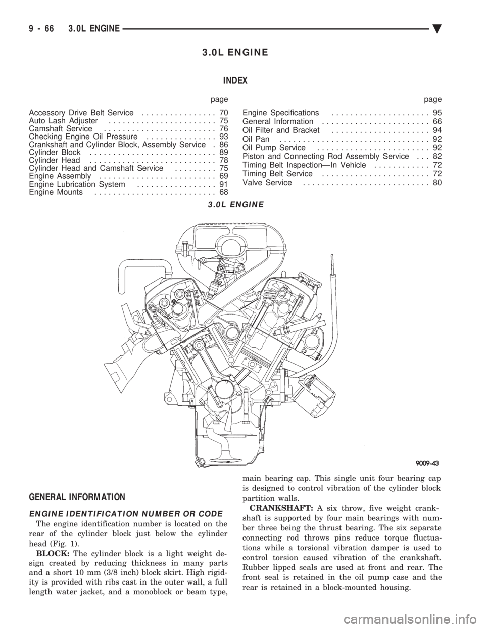
The engine identification number is located on the
rear of the cylinder block just below the cylinder
head (Fig. 1). BLOCK: The cylinder block is a light weight de-
sign created by reducing thickness in many parts
and a short 10 mm (3/8 inch) block skirt. High rigid-
ity is provided with ribs cast in the outer wall, a full
length water jacket, and a monoblock or beam type, main bearing cap. This single unit four bearing cap
is designed to control vibration of the cylinder block
partition walls.
CRANKSHAFT: A six throw, five weight crank-
shaft is supported by four main bearings with num-
ber three being the thrust bearing. The six separate
connecting rod throws pins reduce torque fluctua-
tions while a torsional vibration damper is used to
control torsion caused vibration of the crankshaft.
Rubber lipped seals are used at front and rear. The
front seal is retained in the oil pump case and the
rear is retained in a block-mounted housing.
3.0L ENGINE
9 - 66 3.0L ENGINE Ä
Page 1633 of 2438
PISTONS: Are aluminum alloy with a steel strut,
short height, and thin wall so as to be autothermic
and light weight. The piston head with valve re-
cesses, in combination with the cylinder head, forms
a compact spherical head with clearance for total
valve lift with pistons at top dead center. The piston
skirt, top and second ring lands are finished to a ta-
pered roughness for oil retention and high resistance
to scuffing. Piston pins, press-fitted into place, join
the pistons to the connecting rods. CYLINDER HEAD: The alloy cylinder heads fea- ture cross-flow type intake and exhaust ports. Valve
guides and inserts are hardened cast iron. Valves of
heat resistance steel are arranged i
n a V with each
camshaft on center. To improve combustion speed the
chambers are a compact spherical design with a
squish area of approximately 30 percent of the piston
top area. The cylinder heads are common to either
cylinder bank by reversing the direction of installa-
tion. CAMSHAFTS: Two overhead camshafts provide
valve actuation, one front (radiator side of cylinder
bank) and one rear. The front camshaft is provided
with a distributor drive and is longer. Both cam-
shafts are supported by four bearing journals, thrust
for the front camshaft is taken at journal two and
the rear at journal three. Front and rear camshaft
driving sprockets are interchangeable. The sprockets
and the engine water pump are driven by a single
notched timing belt. ROCKER ARM SHAFTS: The shafts are retained
by the camshaft bearing journal caps. Four shafts are
used, one for each intake and exhaust rocker arm as-
sembly on each cylinder head. The hollow shafts pro-
vide a duct for lubricating oil flow from the cylinder
head to the valve mechanisms. ROCKER ARMS: Are of light weight die-cast
with roller type follower operating against the cam
shaft. The valve actuating end of the rocker arms are
machined to retain hydraulic lash adjusters, elimi-
nating valve lash adjustment. VALVES: Are made of heat resistant steel and are
further treated to resist heat. VALVE SPRINGS: Are especially designed to be
short. The valve spring wire cross-section is oval
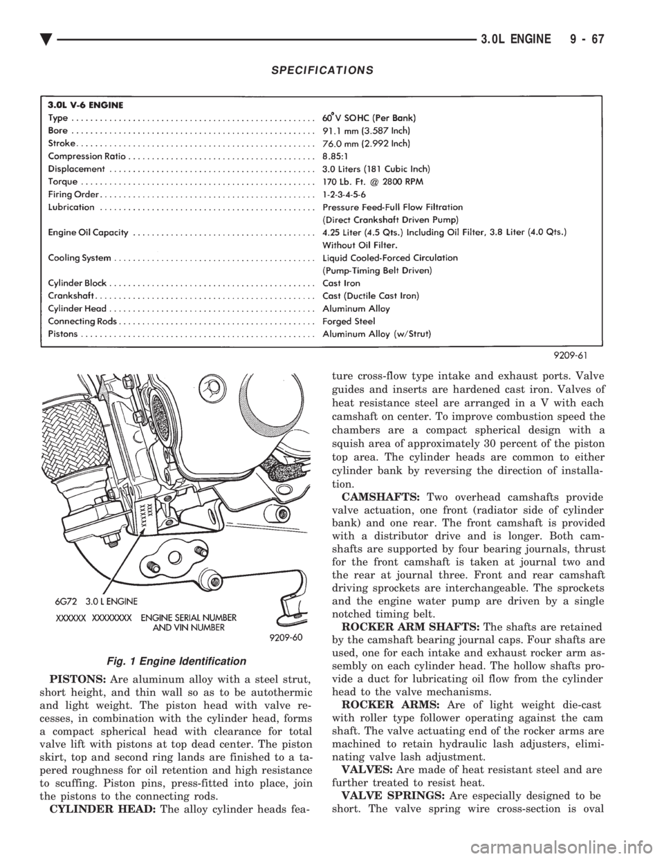
SPECIFICATIONS
Fig. 1 Engine Identification
Ä 3.0L ENGINE 9 - 67
Page 1640 of 2438
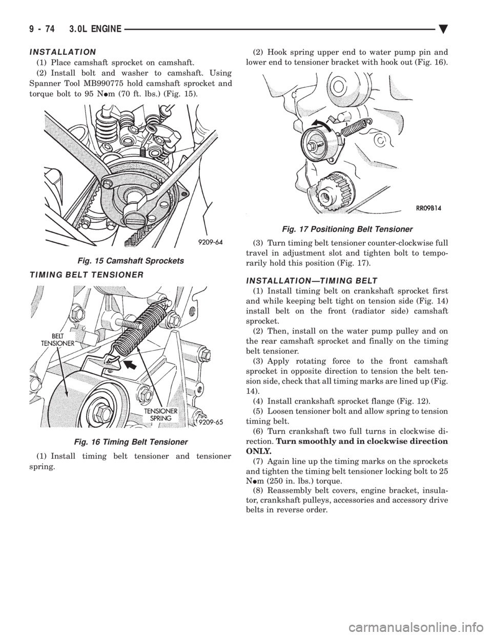
INSTALLATION
(1) Place camshaft sprocket on camshaft.
(2) Install bolt and washer to camshaft. Using
Spanner Tool MB990775 hold camshaft sprocket and
torque bolt to 95 N Im (70 ft. lbs.) (Fig. 15).
TIMING BELT TENSIONER
(1) Install timing belt tensioner and tensioner
spring. (2) Hook spring upper end to water pump pin and
lower end to tensioner bracket with hook out (Fig. 16).
(3) Turn timing belt tensioner counter-clockwise full
travel in adjustment slot and tighten bolt to tempo-
rarily hold this position (Fig. 17).
INSTALLATIONÐTIMING BELT
(1) Install timing belt on crankshaft sprocket first
and while keeping belt tight on tension side (Fig. 14)
install belt on the front (radiator side) camshaft
sprocket. (2) Then, install on the water pump pulley and on
the rear camshaft sprocket and finally on the timing
belt tensioner. (3) Apply rotating force to the front camshaft
sprocket in opposite direction to tension the belt ten-
sion side, check that all timing marks are lined up (Fig.
14). (4) Install crankshaft sprocket flange (Fig. 12).
(5) Loosen tensioner bolt and allow spring to tension
timing belt. (6) Turn crankshaft two full turns in clockwise di-
rection. Turn smoothly and in clockwise direction
ONLY. (7) Again line up the timing marks on the sprockets
and tighten the timing belt tensioner locking bolt to 25
N Im (250 in. lbs.) torque.
(8) Reassembly belt covers, engine bracket, insula-
tor, crankshaft pulleys, accessories and accessory drive
belts in reverse order.
Fig. 15 Camshaft Sprockets
Fig. 16 Timing Belt Tensioner
Fig. 17 Positioning Belt Tensioner
9 - 74 3.0L ENGINE Ä
Page 1664 of 2438
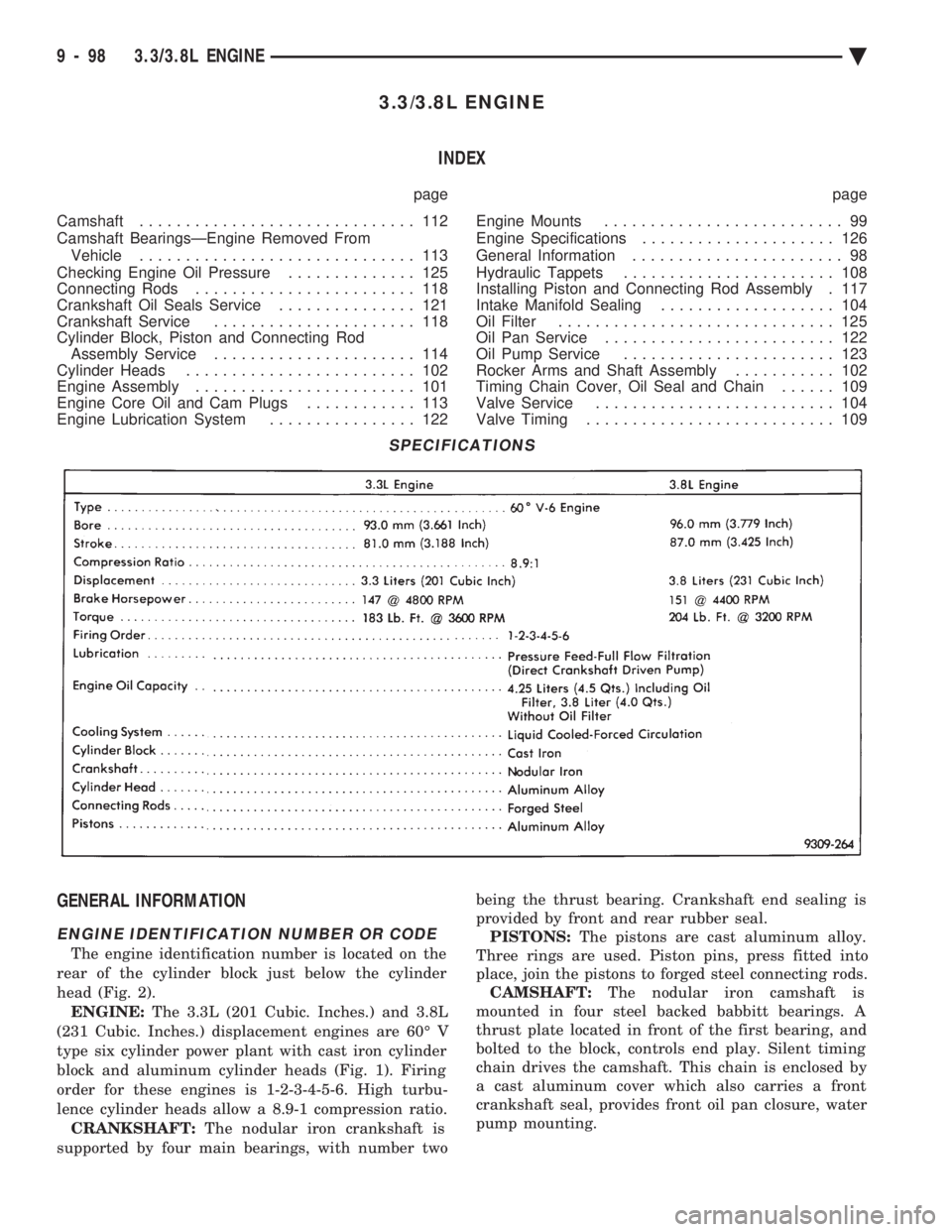
3.3/3.8L ENGINE INDEX
page page
Camshaft .............................. 112
Camshaft BearingsÐEngine Removed From Vehicle .............................. 113
Checking Engine Oil Pressure .............. 125
Connecting Rods ........................ 118
Crankshaft Oil Seals Service ............... 121
Crankshaft Service ...................... 118
Cylinder Block, Piston and Connecting Rod Assembly Service ...................... 114
Cylinder Heads ......................... 102
Engine Assembly ........................ 101
Engine Core Oil and Cam Plugs ............ 113
Engine Lubrication System ................ 122 Engine Mounts
.......................... 99
Engine Specifications ..................... 126
General Information ....................... 98
Hydraulic Tappets ....................... 108
Installing Piston and Connecting Rod Assembly . 117
Intake Manifold Sealing ................... 104
Oil Filter .............................. 125
Oil Pan Service ......................... 122
Oil Pump Service ....................... 123
Rocker Arms and Shaft Assembly ........... 102
Timing Chain Cover, Oil Seal and Chain ...... 109
Valve Service .......................... 104
Valve Timing ........................... 109
GENERAL INFORMATION
ENGINE IDENTIFICATION NUMBER OR CODE
The engine identification number is located on the
rear of the cylinder block just below the cylinder
head (Fig. 2). ENGINE: The 3.3L (201 Cubic. Inches.) and 3.8L
(231 Cubic. Inches.) displacement engines are 60É V
type six cylinder power plant with cast iron cylinder
block and aluminum cylinder heads (Fig. 1). Firing
order for these engines is 1-2-3-4-5-6. High turbu-
lence cylinder heads allow a 8.9-1 compression ratio. CRANKSHAFT: The nodular iron crankshaft is
supported by four main bearings, with number two being the thrust bearing. Crankshaft end sealing is
provided by front and rear rubber seal. PISTONS: The pistons are cast aluminum alloy.
Three rings are used. Piston pins, press fitted into
place, join the pistons to forged steel connecting rods. CAMSHAFT: The nodular iron camshaft is
mounted in four steel backed babbitt bearings. A
thrust plate located in front of the first bearing, and
bolted to the block, controls end play. Silent timing
chain drives the camshaft. This chain is enclosed by
a cast aluminum cover which also carries a front
crankshaft seal, provides front oil pan closure, water
pump mounting.
SPECIFICATIONS
9 - 98 3.3/3.8L ENGINE Ä
Page 1702 of 2438
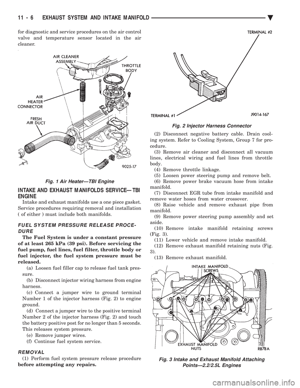
for diagnostic and service procedures on the air control
valve and temperature sensor located in the air
cleaner.
INTAKE AND EXHAUST MANIFOLDS SERVICEÐTBI
ENGINE
Intake and exhaust manifolds use a one piece gasket.
Service procedures requiring removal and installation
( of either ) must include both manifolds.
FUEL SYSTEM PRESSURE RELEASE PROCE- DURE
The Fuel System is under a constant pressure
of at least 265 kPa (39 psi). Before servicing the
fuel pump, fuel lines, fuel filter, throttle body or
fuel injector, the fuel system pressure must be
released. (a) Loosen fuel filler cap to release fuel tank pres-
sure. (b) Disconnect injector wiring harness from engine
harness. (c) Connect a jumper wire to ground terminal
Number 1 of the injector harness (Fig. 2) to engine
ground. (d) Connect a jumper wire to the positive terminal
Number 2 of the injector harness (Fig. 2) and touch
the battery positive post for no longer than 5 seconds.
This releases system pressure. (e) Remove jumper wires.
(f) Continue fuel system service.
REMOVAL
(1) Perform fuel system pressure release procedure
before attempting any repairs. (2) Disconnect negative battery cable. Drain cool-
ing system. Refer to Cooling System, Group 7 for pro-
cedure. (3) Remove air cleaner and disconnect all vacuum
lines, electrical wiring and fuel lines from throttle
body. (4) Remove throttle linkage.
(5) Loosen power steering pump and remove belt.
(6) Remove power brake vacuum hose from intake
manifold. (7) Disconnect EGR tube from intake manifold and
remove water hoses from water crossover. (8) Raise vehicle and remove exhaust pipe from
manifold. (9) Remove power steering pump assembly and set
aside. (10) Remove intake manifold retaining screws
(Fig. 3). (11) Lower vehicle and remove intake manifold.
(12) Remove exhaust manifold retaining nuts (Fig.
3). (13) Remove exhaust manifold.
Fig. 2 Injector Harness Connector
Fig. 3 Intake and Exhaust Manifold Attaching PointsÐ2.2/2.5L Engines
Fig. 1 Air HeaterÐTBI Engine
11 - 6 EXHAUST SYSTEM AND INTAKE MANIFOLD Ä