water pump CHEVROLET DYNASTY 1993 User Guide
[x] Cancel search | Manufacturer: CHEVROLET, Model Year: 1993, Model line: DYNASTY, Model: CHEVROLET DYNASTY 1993Pages: 2438, PDF Size: 74.98 MB
Page 353 of 2438
INSPECTION Replace water pump body assembly if it has any of
these defects: (1) Cracks or damage on the body.
(2) Water leaks from the shaft seal, evident by
coolant traces below the vent hole. (3) Loose or rough turning bearing.
(4) Impeller rubs either the pump body or the hous-
ing.
ASSEMBLY
Body assembly and housing are serviced as separate
components. (1) Install new O-ring gasket in body O-ring groove.
(2) Assemble pump body to housing and tighten nine
screws to 12 N Im (105 in. lbs.) (Fig. 2).
(3) Rotate pump by hand to check for freedom of
movement. (4) Position water pump pulley to water pump.In-
stall three screws and tighten to 30 N Im (250 in. lbs.).
(5) Position new O-ring in housing to block O-ring
groove.
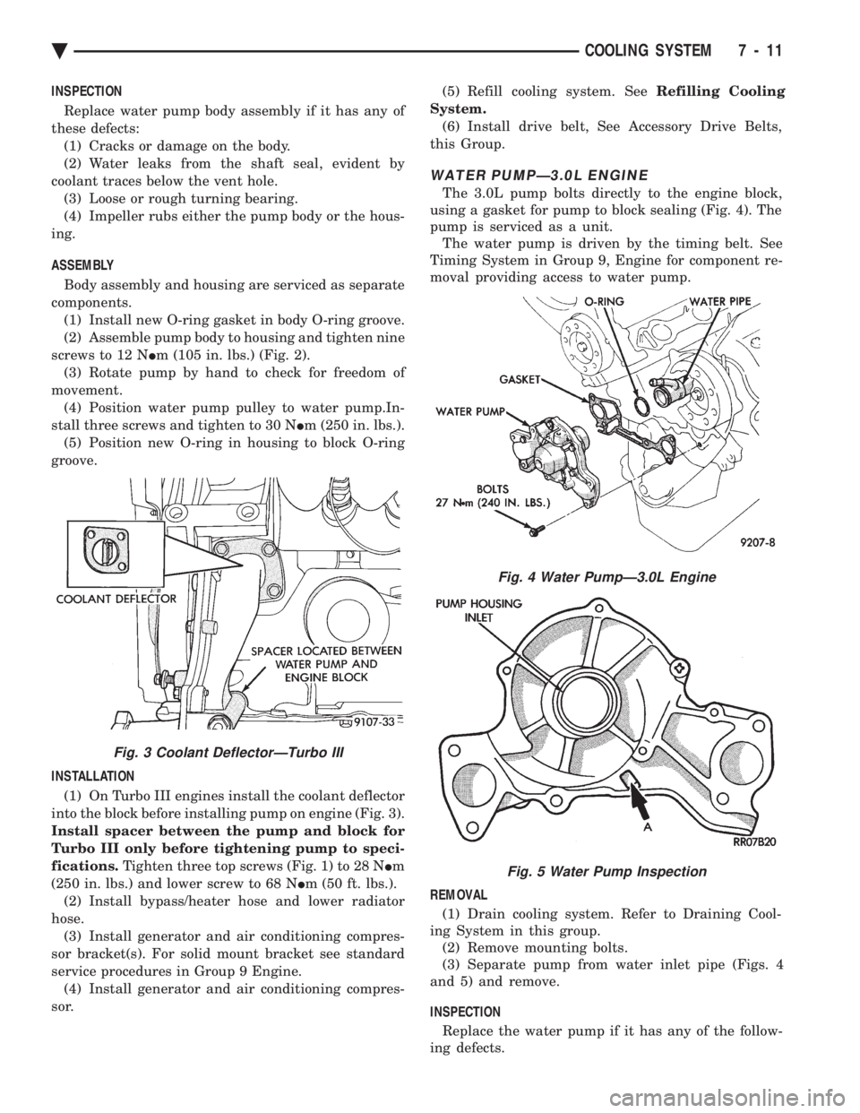
INSTALLATION (1) On Turbo III engines install the coolant deflector
into the block before installing pump on engine (Fig. 3).
Install spacer between the pump and block for
Turbo III only before tightening pump to speci-
fications. Tighten three top screws (Fig. 1) to 28 N Im
(250 in. lbs.) and lower screw to 68 N Im (50 ft. lbs.).
(2) Install bypass/heater hose and lower radiator
hose. (3) Install generator and air conditioning compres-
sor bracket(s). For solid mount bracket see standard
service procedures in Group 9 Engine. (4) Install generator and air conditioning compres-
sor. (5) Refill cooling system. See
Refilling Cooling
System. (6) Install drive belt, See Accessory Drive Belts,
this Group.
WATER PUMPÐ3.0L ENGINE
The 3.0L pump bolts directly to the engine block,
using a gasket for pump to block sealing (Fig. 4). The
pump is serviced as a unit. The water pump is driven by the timing belt. See
Timing System in Group 9, Engine for component re-
moval providing access to water pump.
REMOVAL (1) Drain cooling system. Refer to Draining Cool-
ing System in this group. (2) Remove mounting bolts.
(3) Separate pump from water inlet pipe (Figs. 4
and 5) and remove.
INSPECTION Replace the water pump if it has any of the follow-
ing defects.
Fig. 4 Water PumpÐ3.0L Engine
Fig. 5 Water Pump Inspection
Fig. 3 Coolant DeflectorÐTurbo III
Ä COOLING SYSTEM 7 - 11
Page 354 of 2438
(1) Damage or cracks on the pump body.
(2) Coolant leaks, if the shaft seal is leaking, evi-
dent by traces of coolant leaks from vent hole A in
(Fig. 5). (3) Impeller rubs inside of pump.
(4) Excessively loose or rough turning bearing.
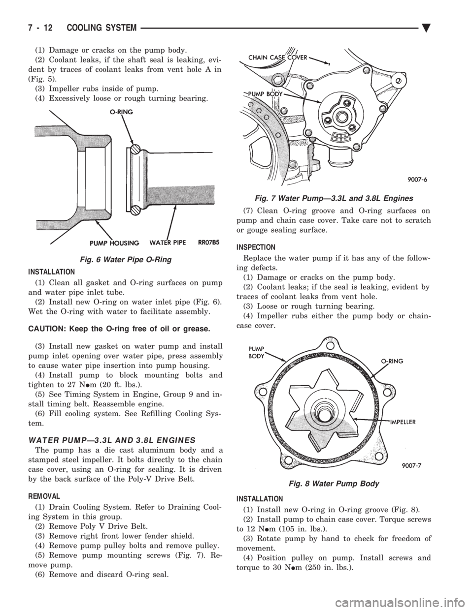
INSTALLATION (1) Clean all gasket and O-ring surfaces on pump
and water pipe inlet tube. (2) Install new O-ring on water inlet pipe (Fig. 6).
Wet the O-ring with water to facilitate assembly.
CAUTION: Keep the O-ring free of oil or grease.
(3) Install new gasket on water pump and install
pump inlet opening over water pipe, press assembly
to cause water pipe insertion into pump housing. (4) Install pump to block mounting bolts and
tighten to 27 N Im (20 ft. lbs.).
(5) See Timing System in Engine, Group 9 and in-
stall timing belt. Reassemble engine. (6) Fill cooling system. See Refilling Cooling Sys-
tem.
WATER PUMPÐ3.3L AND 3.8L ENGINES
The pump has a die cast aluminum body and a
stamped steel impeller. It bolts directly to the chain
case cover, using an O-ring for sealing. It is driven
by the back surface of the Poly-V Drive Belt.
REMOVAL (1) Drain Cooling System. Refer to Draining Cool-
ing System in this group. (2) Remove Poly V Drive Belt.
(3) Remove right front lower fender shield.
(4) Remove pump pulley bolts and remove pulley.
(5) Remove pump mounting screws (Fig. 7). Re-
move pump. (6) Remove and discard O-ring seal. (7) Clean O-ring groove and O-ring surfaces on
pump and chain case cover. Take care not to scratch
or gouge sealing surface.
INSPECTION
Replace the water pump if it has any of the follow-
ing defects. (1) Damage or cracks on the pump body.
(2) Coolant leaks; if the seal is leaking, evident by
traces of coolant leaks from vent hole. (3) Loose or rough turning bearing.
(4) Impeller rubs either the pump body or chain-
case cover.
INSTALLATION
(1) Install new O-ring in O-ring groove (Fig. 8).
(2) Install pump to chain case cover. Torque screws
to 12 N Im (105 in. lbs.).
(3) Rotate pump by hand to check for freedom of
movement. (4) Position pulley on pump. Install screws and
torque to 30 N Im (250 in. lbs.).
Fig. 6 Water Pipe O-Ring
Fig. 7 Water PumpÐ3.3L and 3.8L Engines
Fig. 8 Water Pump Body
7 - 12 COOLING SYSTEM Ä
Page 355 of 2438
(5) Install drive belt. See Accessory Drive Belts
this group. (6) Install right front lower fender shield.
(7) Refill Cooling System. See Refilling Cooling
System in this section.
ENGINE THERMOSTATS
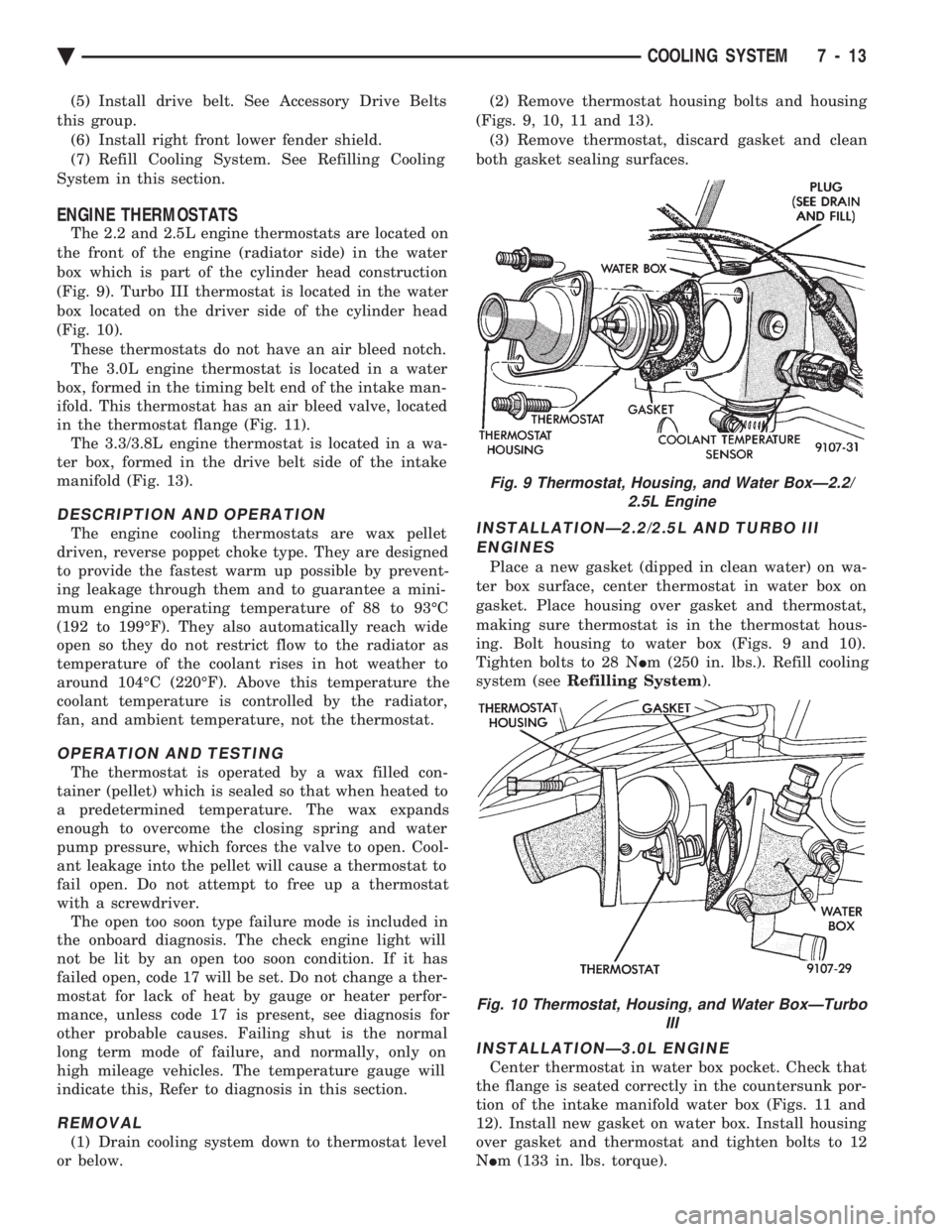
The 2.2 and 2.5L engine thermostats are located on
the front of the engine (radiator side) in the water
box which is part of the cylinder head construction
(Fig. 9). Turbo III thermostat is located in the water
box located on the driver side of the cylinder head
(Fig. 10). These thermostats do not have an air bleed notch.
The 3.0L engine thermostat is located in a water
box, formed in the timing belt end of the intake man-
ifold. This thermostat has an air bleed valve, located
in the thermostat flange (Fig. 11). The 3.3/3.8L engine thermostat is located in a wa-
ter box, formed in the drive belt side of the intake
manifold (Fig. 13).
DESCRIPTION AND OPERATION
The engine cooling thermostats are wax pellet
driven, reverse poppet choke type. They are designed
to provide the fastest warm up possible by prevent-
ing leakage through them and to guarantee a mini-
mum engine operating temperature of 88 to 93ÉC
(192 to 199ÉF). They also automatically reach wide
open so they do not restrict flow to the radiator as
temperature of the coolant rises in hot weather to
around 104ÉC (220ÉF). Above this temperature the
coolant temperature is controlled by the radiator,
fan, and ambient temperature, not the thermostat.
OPERATION AND TESTING
The thermostat is operated by a wax filled con-
tainer (pellet) which is sealed so that when heated to
a predetermined temperature. The wax expands
enough to overcome the closing spring and water
pump pressure, which forces the valve to open. Cool-
ant leakage into the pellet will cause a thermostat to
fail open. Do not attempt to free up a thermostat
with a screwdriver. The open too soon type failure mode is included in
the onboard diagnosis. The check engine light will
not be lit by an open too soon condition. If it has
failed open, code 17 will be set. Do not change a ther-
mostat for lack of heat by gauge or heater perfor-
mance, unless code 17 is present, see diagnosis for
other probable causes. Failing shut is the normal
long term mode of failure, and normally, only on
high mileage vehicles. The temperature gauge will
indicate this, Refer to diagnosis in this section.
REMOVAL
(1) Drain cooling system down to thermostat level
or below. (2) Remove thermostat housing bolts and housing
(Figs. 9, 10, 11 and 13). (3) Remove thermostat, discard gasket and clean
both gasket sealing surfaces.
INSTALLATIONÐ2.2/2.5L AND TURBO III ENGINES
Place a new gasket (dipped in clean water) on wa-
ter box surface, center thermostat in water box on
gasket. Place housing over gasket and thermostat,
making sure thermostat is in the thermostat hous-
ing. Bolt housing to water box (Figs. 9 and 10).
Tighten bolts to 28 N Im (250 in. lbs.). Refill cooling
system (see Refilling System ).
INSTALLATIONÐ3.0L ENGINE
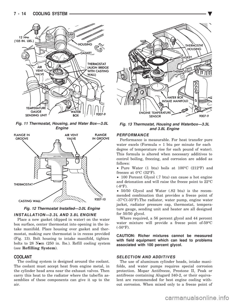
Center thermostat in water box pocket. Check that
the flange is seated correctly in the countersunk por-
tion of the intake manifold water box (Figs. 11 and
12). Install new gasket on water box. Install housing
over gasket and thermostat and tighten bolts to 12
N Im (133 in. lbs. torque).
Fig. 9 Thermostat, Housing, and Water BoxÐ2.2/
2.5L Engine
Fig. 10 Thermostat, Housing, and Water BoxÐTurbo III
Ä COOLING SYSTEM 7 - 13
Page 356 of 2438
INSTALLATIONÐ3.3L AND 3.8L ENGINE
Place a new gasket (dipped in water) on the water
box surface, center thermostat into opening in the in-
take manifold. Place housing over gasket and ther-
mostat, making sure thermostat is in recess provided
(Fig. 13). Bolt housing to intake manifold, tighten
bolts to 28 N Im (250 in. lbs.). Refill cooling system
(see Refilling System ).
COOLANT
The cooling system is designed around the coolant.
The coolant must accept heat from engine metal, in
the cylinder head area near the exhaust valves. Then
carry this heat to the radiator where the tube/fin as-
semblies of these components can give it up to the
air.
PERFORMANCE
Performance is measurable. For heat transfer pure
water excels (Formul a = 1 btu per minute for each
degree of temperature rise for each pound of water).
This formula is altered when necessary additives to
control boiling, freezing, and corrosion are added as
follows:
² Pure Water (1 btu) boils at 100ÉC (212ÉF) and
freezes at 0ÉC (32ÉF).
² 100 Percent Glycol (.7 btu) can cause a hot engine
and detonation and will raise the freeze point to 22ÉC
(-8ÉF).
² 50/50 Glycol and Water (.82 btu) is the recom-
mended combination that provides a freeze point of
-37ÉC(-35ÉF).The radiator, water pump, engine water
jacket, radiator pressure cap, thermostat, tempera-
ture gauge, sending unit and heater are all designed
for 50/50 glycol. Where required, a 56 percent glycol and 44 percent
water mixture will provide a freeze point of-59ÉC
(-50ÉF).
CAUTION: Richer mixtures cannot be measured
with field equipment which can lead to problems
associated with 100 percent glycol.
SELECTION AND ADDITIVES
The use of aluminum cylinder heads, intake mani-
folds, and water pumps requires special corrosion
protection. Mopar Antifreeze, Prestone II, Peak or
antifreeze containing Alugard 340-2, or their equiva-
lent are recommended for best engine cooling with-
out corrosion. When mixed only to a freeze point of
Fig. 11 Thermostat, Housing, and Water BoxÐ3.0L Engine
Fig. 12 Thermostat InstalledÐ3.0L Engine
Fig. 13 Thermostat, Housing and WaterboxÐ3.3Land 3.8L Engine
7 - 14 COOLING SYSTEM Ä
Page 357 of 2438
-37ÉC (-35ÉF) to -59ÉC (-50ÉF). If it looses color or
becomes contaminated, drain, flush, and replace with
fresh properly mixed solution.
SERVICE
Coolant should be changed at 52,500 miles or three
years, whichever occurs first, then every two years or
30,000 miles.
ROUTINE LEVEL CHECK
Do not remove radiator cap for routine coolant
level inspections. The coolant reserve system provides a quick visual
method for determining the coolant level without re-
moving the radiator cap. Simply observe, with the
engine idling and warmed up to normal operating
temperature, that the level of the coolant in the reserve
tank (Figs. 5 and 6) is between the minimum and
maximum marks.
ADDING ADDITIONAL COOLANT
The radiator cap should not be removed. When
additional coolant is needed to maintain this level, it
should be added to the coolant reserve tank. Use only
50/50 concentration of ethylene glycol type antifreeze
and water.
SERVICE COOLANT LEVEL
The cooling system is closed and designed to main-
tain coolant level to the top of the radiator. When servicing requires a coolant level check in the
radiator, the engine must be offand notunder pres-
sure. Drain several ounces of coolant from the radiator
drain cock while observing the Coolant Recovery Sys-
tem (CRS) Tank. Coolant level in the CRS tank should
drop slightly. Then remove the radiator cap. The radia-
tor should be full to the top. If not, and the coolant level
in the CRS tank is at the MIN mark there is a air leak
in the CRS system. Check hose or hose connections to
the CRS tank, radiator filler neck or the pressure cap
seal to the radiator filler neck for leaks.
LOW COOLANT LEVEL AERATION
Low coolant level in a cross flow radiator will equal-
ize in both tanks with engine off. With engine at
running operating temperature the high pressure inlet
tank runs full and the low pressure outlet tank drops.
If this level drops below the top of the transmission oil
cooler, air will be sucked into the water pump:
² Transmission oil will become hotter.
² High reading shown on the temperature gauge.
² Air in the coolant will also cause loss of flow through
the heater.
² Exhaust gas leaks into the coolant can also cause the
same problems.
DEAERATION
Air can only be removed from the system by gather-
ing under the pressure cap. On the next heat up it will
be pushed past the pressure cap into the CRS tank by
thermal expansion of the coolant. It then escapes to the
atmosphere in the CRS tank and is replaced with solid
coolant on cool down.
COOLING SYSTEM DRAIN, CLEAN, FLUSH AND
REFILL
Drain, flush, and fill the cooling system at the
mileage or time intervals specified in the Maintenance
Schedule in this Group. If the solution is dirty or rusty
or contains a considerable amount of sediment, clean
and flush with a reliable cooling system cleaner. Care
should be taken in disposing of the used engine coolant
from your vehicle. Check governmental regulations for
disposal of used engine coolant.
DRAINING
To drain cooling system move temperature selector
for heater to full heat with engine running (to provide
vacuum for actuation). Without removing radiator
pressure cap and with system not under pres-
sure, Shut engine off and open draincock. The coolant
reserve tank (Fig. 5) should empty first, then remove
radiator pressure cap. (if not, see Testing Cooling
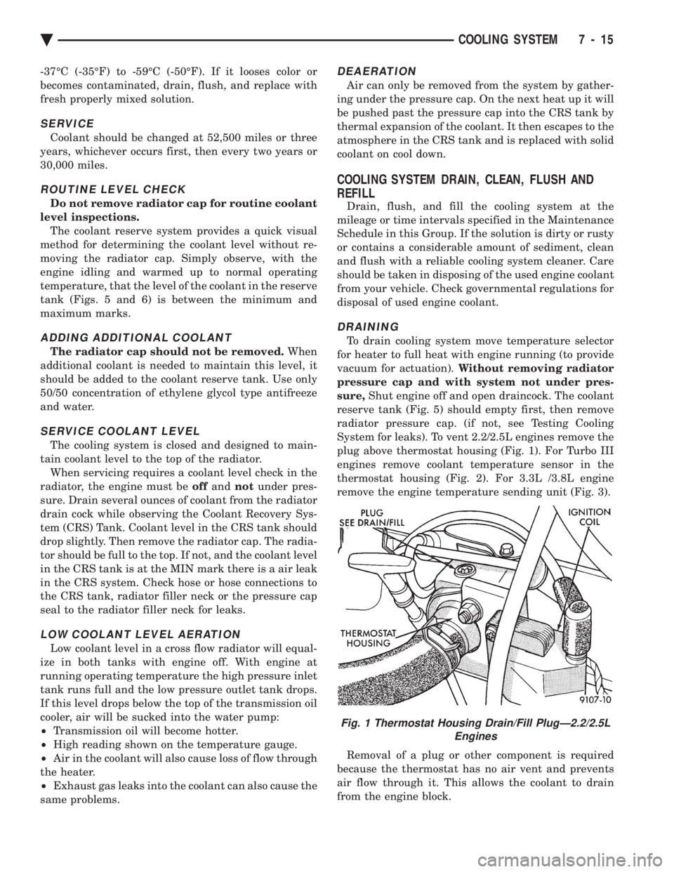
System for leaks). To vent 2.2/2.5L engines remove the
plug above thermostat housing (Fig. 1). For Turbo III
engines remove coolant temperature sensor in the
thermostat housing (Fig. 2). For 3.3L /3.8L engine
remove the engine temperature sending unit (Fig. 3).
Removal of a plug or other component is required
because the thermostat has no air vent and prevents
air flow through it. This allows the coolant to drain
from the engine block.
Fig. 1 Thermostat Housing Drain/Fill PlugÐ2.2/2.5L Engines
Ä COOLING SYSTEM 7 - 15
Page 360 of 2438
RADIATOR PRESSURE CAP
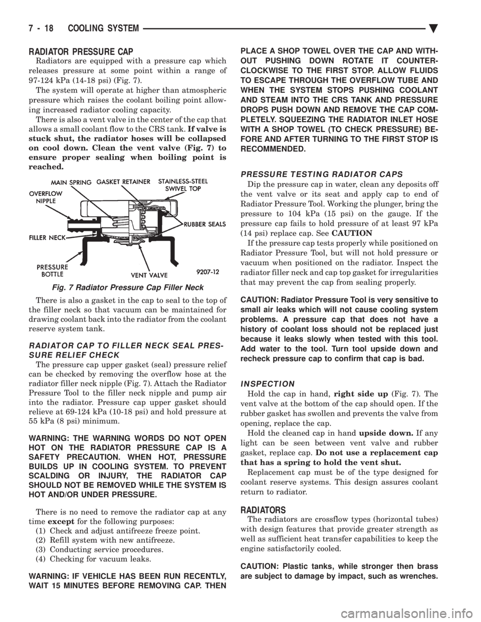
Radiators are equipped with a pressure cap which
releases pressure at some point within a range of
97-124 kPa (14-18 psi) (Fig. 7). The system will operate at higher than atmospheric
pressure which raises the coolant boiling point allow-
ing increased radiator cooling capacity. There is also a vent valve in the center of the cap that
allows a small coolant flow to the CRS tank. If valve is
stuck shut, the radiator hoses will be collapsed
on cool down. Clean the vent valve (Fig. 7) to
ensure proper sealing when boiling point is
reached.
There is also a gasket in the cap to seal to the top of
the filler neck so that vacuum can be maintained for
drawing coolant back into the radiator from the coolant
reserve system tank.
RADIATOR CAP TO FILLER NECK SEAL PRES- SURE RELIEF CHECK
The pressure cap upper gasket (seal) pressure relief
can be checked by removing the overflow hose at the
radiator filler neck nipple (Fig. 7). Attach the Radiator
Pressure Tool to the filler neck nipple and pump air
into the radiator. Pressure cap upper gasket should
relieve at 69-124 kPa (10-18 psi) and hold pressure at
55 kPa (8 psi) minimum.
WARNING: THE WARNING WORDS DO NOT OPEN
HOT ON THE RADIATOR PRESSURE CAP IS A
SAFETY PRECAUTION. WHEN HOT, PRESSURE
BUILDS UP IN COOLING SYSTEM. TO PREVENT
SCALDING OR INJURY, THE RADIATOR CAP
SHOULD NOT BE REMOVED WHILE THE SYSTEM IS
HOT AND/OR UNDER PRESSURE.
There is no need to remove the radiator cap at any
time except for the following purposes:
(1) Check and adjust antifreeze freeze point.
(2) Refill system with new antifreeze.
(3) Conducting service procedures.
(4) Checking for vacuum leaks.
WARNING: IF VEHICLE HAS BEEN RUN RECENTLY,
WAIT 15 MINUTES BEFORE REMOVING CAP. THEN PLACE A SHOP TOWEL OVER THE CAP AND WITH-
OUT PUSHING DOWN ROTATE IT COUNTER-
CLOCKWISE TO THE FIRST STOP. ALLOW FLUIDS
TO ESCAPE THROUGH THE OVERFLOW TUBE AND
WHEN THE SYSTEM STOPS PUSHING COOLANT
AND STEAM INTO THE CRS TANK AND PRESSURE
DROPS PUSH DOWN AND REMOVE THE CAP COM-
PLETELY. SQUEEZING THE RADIATOR INLET HOSE
WITH A SHOP TOWEL (TO CHECK PRESSURE) BE-
FORE AND AFTER TURNING TO THE FIRST STOP IS
RECOMMENDED.
PRESSURE TESTING RADIATOR CAPS
Dip the pressure cap in water, clean any deposits off
the vent valve or its seat and apply cap to end of
Radiator Pressure Tool. Working the plunger, bring the
pressure to 104 kPa (15 psi) on the gauge. If the
pressure cap fails to hold pressure of at least 97 kPa
(14 psi) replace cap. See CAUTION
If the pressure cap tests properly while positioned on
Radiator Pressure Tool, but will not hold pressure or
vacuum when positioned on the radiator. Inspect the
radiator filler neck and cap top gasket for irregularities
that may prevent the cap from sealing properly.
CAUTION: Radiator Pressure Tool is very sensitive to
small air leaks which will not cause cooling system
problems. A pressure cap that does not have a
history of coolant loss should not be replaced just
because it leaks slowly when tested with this tool.
Add water to the tool. Turn tool upside down and
recheck pressure cap to confirm that cap is bad.
INSPECTION
Hold the cap in hand, right side up(Fig. 7). The
vent valve at the bottom of the cap should open. If the
rubber gasket has swollen and prevents the valve from
opening, replace the cap. Hold the cleaned cap in hand upside down.If any
light can be seen between vent valve and rubber
gasket, replace cap. Do not use a replacement cap
that has a spring to hold the vent shut. Replacement cap must be of the type designed for
coolant reserve systems. This design assures coolant
return to radiator.
RADIATORS
The radiators are crossflow types (horizontal tubes)
with design features that provide greater strength as
well as sufficient heat transfer capabilities to keep the
engine satisfactorily cooled.
CAUTION: Plastic tanks, while stronger then brass
are subject to damage by impact, such as wrenches.
Fig. 7 Radiator Pressure Cap Filler Neck
7 - 18 COOLING SYSTEM Ä
Page 368 of 2438
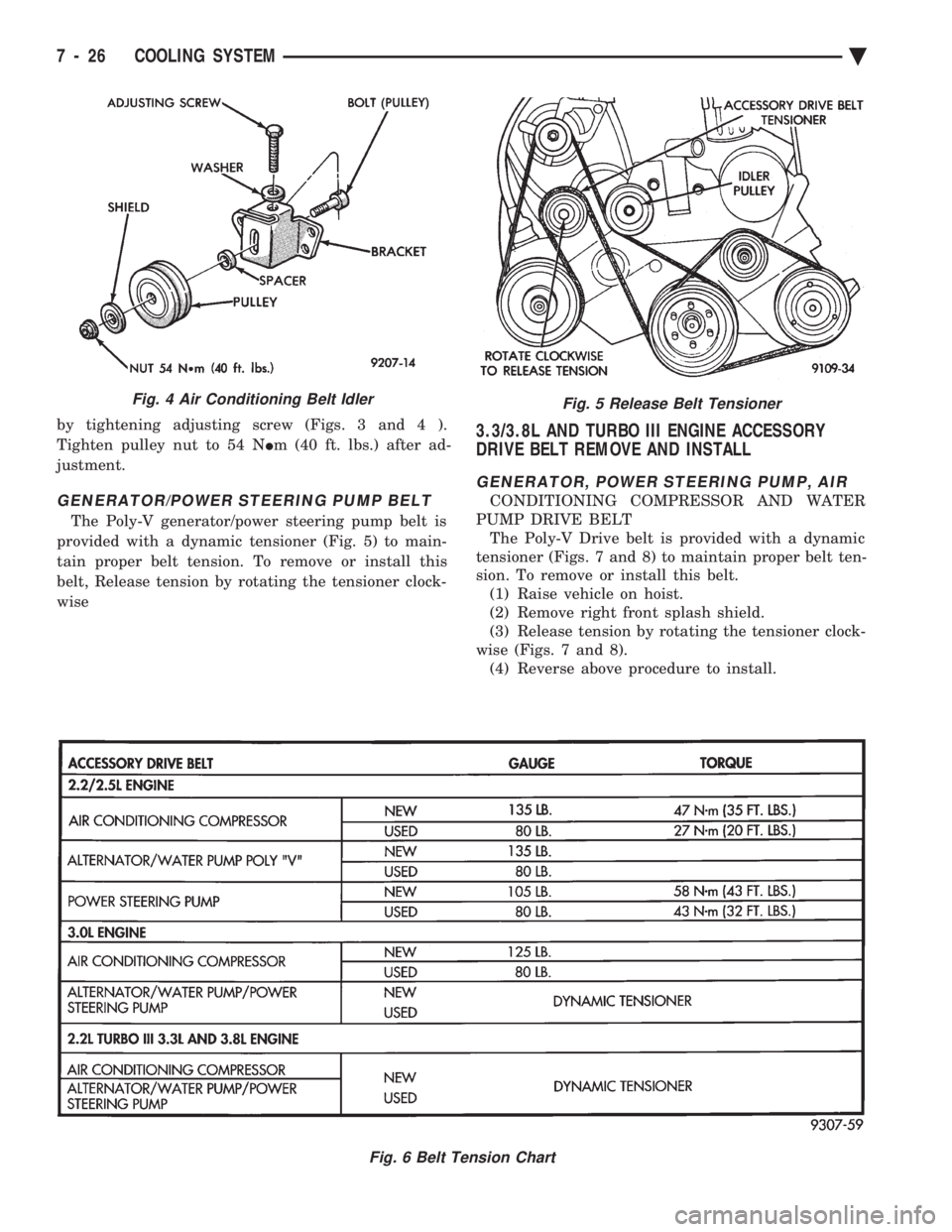
by tightening adjusting screw (Figs. 3 and 4 ).
Tighten pulley nut to 54 N Im (40 ft. lbs.) after ad-
justment.
GENERATOR/POWER STEERING PUMP BELT
The Poly-V generator/power steering pump belt is
provided with a dynamic tensioner (Fig. 5) to main-
tain proper belt tension. To remove or install this
belt, Release tension by rotating the tensioner clock-
wise
3.3/3.8L AND TURBO III ENGINE ACCESSORY
DRIVE BELT REMOVE AND INSTALL
GENERATOR, POWER STEERING PUMP, AIR
CONDITIONING COMPRESSOR AND WATER
PUMP DRIVE BELT The Poly-V Drive belt is provided with a dynamic
tensioner (Figs. 7 and 8) to maintain proper belt ten-
sion. To remove or install this belt. (1) Raise vehicle on hoist.
(2) Remove right front splash shield.
(3) Release tension by rotating the tensioner clock-
wise (Figs. 7 and 8). (4) Reverse above procedure to install.
Fig. 5 Release Belt Tensioner
Fig. 6 Belt Tension Chart
Fig. 4 Air Conditioning Belt Idler
7 - 26 COOLING SYSTEM Ä
Page 1063 of 2438
WIRING DIAGRAMS AC-AY BODY INDEX
Wiring Diagram
Name Sheet Number
ABS Data Link Connector ........................49
Airbag System ........................... .57, 58
Clockspring ...............................57
Diagnostic Module ..........................57
Interface Grommet ..........................58
Sensor-Left ...............................58
Sensor-Right ..............................58
Squib (Airbag Igniter) ........................57
Air Conditioning and Heater System (2.5L) .............53
A/C Switch ...............................53
Blower Motor ..............................53
Compressor ...............................53
Defrost Switch .............................53
Diode ...................................53
Illumination Lamps ..........................53
Low Pressure Switch .........................53
Resistor .................................53
Switch-Blower .............................53
Air Conditioning Variable Output Compressor ..........113
Air Exhaust Solenoid-Automatic Air Load Leveling ........40
Air Suspension System .................41, 42, 43, 44
Air Exhaust Solenoid .........................42
Air Suspension Relay .........................42
Air Suspension System Control Module .......41, 43, 176
Compressor Assembly ........................42
Compressor Motor ..........................42
Height Sensors ............................44
Shock Absorber ............................43
Solenoids ............................ .41, 44
Air Suspension System Control Module .........41, 43, 176
Antennas ............................. .118, 126
Anti-Lock Brake System ............45, 46, 47, 48, 49, 50
ABS System Relay ..........................47
Controller .................. .45, 46, 47, 48, 49, 50
Data Link Connector .........................49
Left Front Wheel Sensor .......................50
Left Rear Wheel Sensor .......................50
Modulator ............................ .45, 48
Pump Motor ..............................46
Pump and Motor Relay .......................46
Right Front Wheel Sensor ......................50
Right Rear Wheel Sensor ......................50
Yellow Lamp Relay ..........................49
Anti-Lock Brake System Controller .....45, 46, 47, 48, 49, 50
Anti-Lock Brake System Modulator Connectors .........172
Anti-Lock Brake System Controller Connector ..........175
Anti-Lock Brake System Modulator ...............45, 48
ATC In-line Connector ........................ .117
Automatic Air Load Leveling System ..............39, 40
Air Exhaust Solenoid .........................40
Compressor Assembly ........................40
Compressor Motor ..........................40Wiring Diagram
Name Sheet Number
Load Leveling Relay .........................40
Shock Absorber ............................40
Automatic Day/Night Mirror .................... .124
Automatic Temperature Control .............115, 116, 117
A/C Blower Motor ......................... .115
Ambient Sensor .......................... .117
ATC Control Switch ........................ .116
ATC In Line Connector ...................... .117
ATC Power Module ........................ .115
In Car Senso r............................ .115
In Car Sensor Motor ....................... .115
Sun Sensor ............................. .115
Water Sensor ............................ .117
Automatic Temperature Control (Radiator and
Compressor 3.3L & 3.8L) .................. .113, 114
A/C Ambient Temperature Switch ................114
A/C Compressor Clutch Relay ...................113
A/C Fan Cutout Switch ...................... .114
A/C High Pressure Cutout Switch ................114
A/C Low Pressure Switch .................... .114
A/C Variable Output Compressor .................113
Diode ................................. .113
Radiator Fan Motor ........................ .113
Radiator Fan Relay ........................ .114
Automatic Shutdown Relay .......................29
Automatic Temperature Control In-line Connector ........206
Automatic Temperature Control Module Connector .......200
Back-Up Lamp Relay ..........................33
Battery ...............................2,5,7,9
Body Computer 2 (Electronic Cluster) .........101, 102, 194
25-Pin Connector ...................... .101, 102
Body Computer 1 (Electronic Cluster) .........103, 104, 195
25-Pin Connector ...................... .103, 104
Data Link Connector ....................... .103
Halo Lamp .............................. .104
Relay ................................. .103
Body Computer (Mechanical Cluster w/Visual Message Ctr) ......................... .196, 197
Body Computer (Mechanical Cluster w/o Visual Message Ctr) ......................... .198, 199
Body Computer 1 (Mechanical Cluster w/o Visual Message Ctr) ..................... .108, 109, 110
25-Pin Connector ................... .108, 109, 110
Data Link Connector ....................... .110
Halo Lamp .............................. .108
Key-In Switch ............................ .109
Relay Bank ............................. .108
Body Computer 2 (Mechanical Cluster with Visual Message Ctr) ..................... .105, 106, 107
25-Pin Connector ................... .105, 106, 107
Data Link Connector ....................... .106
Halo Lamp .............................. .106
Key-In Switch ............................ .107
Ä WIRING DIAGRAMS AC-AY BODY 8W - 313
Page 1069 of 2438
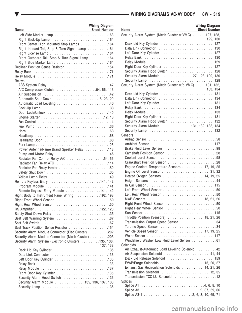
Wiring Diagram
Name Sheet Number
Left Side Marker Lamp ...................... .163
Right Back-Up Lamp ....................... .164
Right Center High Mounted Stop Lamps ............164
Right Inboard Tail, Stop & Turn Signal Lamp .........164
Right License Lamp ........................ .164
Right Outboard Tail, Stop & Turn Signal Lamp ........164
Right Side Marker Lamp ..................... .164
Recliner Position Sense Resistor ..................154
Relay Bank ............................... .171
Relay Module ............................. .171
Relays ABS System Relay ..........................47
A/C Compressor Clutch .................54, 56, 113
Air Suspension .............................42
Automatic Shut Down .................. .15, 23, 29
Automatic Load Leveling .......................40
Back-Up Lamp .............................33
Door Lock/Unlock ......................... .140
Engine Starter .......................... .12, 13
Fan Control ............................. .114
Fuel Pump ...............................36
Horn ...................................63
Headlamp ................................68
Headlamp Door ............................68
Park Lamp .............................. .125
Power Antenna/Name Brand Speaker Relay ..........118
Pump and Motor Relay .......................46
Radiator Fan Control Relay A/C ................54, 56
Radiator Fan Relay ATC ..................... .114
Radiator Fan Relay-Heater ......................52
Safety Shut Down ...........................35
Yellow Lamp Relay ..........................49
Remote Keyless Entry ..................... .141, 142
Program Module .......................... .141
Remote Keyless Entry Module ...............141, 142
Right Body to Instrument Panel Wiring ...........192, 193
Right Front Wheel Sensor .......................50
Right Rear Wheel Sensor ........................50
RS Amplifier ........................... .122, 123
Safety Shut Down Relay ........................35
Seat Belt Warning System .......................67
Seat Belt Switch .............................67
Seat Track Position Sense Resistor .................154
Security Alarm Module Connector (Elec Cluster) ........202
Security Alarm Module Connector (Mech Cluster) ........203
Security Alarm System (Electronic Cluster) ........135, 136,
137, 138
Deck Lid Key Cylinder ...................... .135
Data Link Connector ....................... .136
Left Door Key Cylinder ...................... .135
Relay Bank ............................. .138
Relay Module ............................ .137
Right Door Key Cylinder ..................... .135
Security Alarm Hood Switch ...................136
Security Alarm Module .............135, 136, 137, 138
Security Lamp ........................... .136Wiring Diagram
Name Sheet Number
Security Alarm System (Mech Cluster w/VMC) ......127, 128,
129, 130
Deck Lid Key Cylinder ...................... .127
Data Link Connector ....................... .130
Left Door Key Cylinder ...................... .127
Relay Bank ............................. .130
Relay Module ............................ .129
Right Door Key Cylinder ..................... .127
Security Alarm Hood Switch ...................128
Security Alarm Module .............127, 128, 129, 130
Security Lamp ........................... .128
Security Alarm System (Mech Cluster w/o VMC) . . . .131, 132,
133, 134
Deck Lid Key Cylinder ...................... .131
Data Link Connector ....................... .134
Left Door Key Cylinder ...................... .131
Relay Bank ............................. .134
Relay Module ............................ .133
Right Door Key Cylinder ..................... .131
Security Alarm Hood Switch ...................132
Security Alarm Module .............131, 132, 133, 134
Security Lamp ........................... .132
Sensors Airbag Sensor .............................58
Ambient Sensor .......................... .117
Brake Fluid Level Sensor ......................98
Camshaft Position Sensor ......................28
Coolant Level Sensor .........................98
Crankshaft Position Sensor .....................28
Engine Coolant Temperature Sensors ..........17, 19, 25
Engine Oil Level Sensor .................... .31, 32
Heated Oxygen Sensors ................. .14, 19, 25
Height Sensors ............................44
In Car Senso r............................ .115
Left Front Wheel Sensor .......................50
Left Rear Wheel Sensor .......................50
MAP Sensors ........................ .18, 21, 26
Right Front Wheel Sensor ......................50
Right Rear Wheel Sensor ......................50
Sun Sensor ............................. .115
Throttle Position (Sensors) ................18, 21, 26
Transmission Output Speed Sensor ................34
Turbine Speed Sensor ........................34
Vehicle Speed Sensor .................. .17, 19, 25
Water Sensor ............................ .117
Windshield Washer Low Fluid Level Sensor ...........61
Solenoids Air Exhaust-Automatic Load Leveling Solenoid .........42
Air Suspension Solenoid ................... .41, 44
Deck Lid Release Solenoid ................... .159
EVAP/Purge Solenoids .................. .15, 20, 27
Exhaust Gas Recirculation Solenoids ..........14, 21, 26
Transmission Solenoid .................... .12, 35
Transmission TCC LU Solenoid ..................12
Splices Splice A1 ...........................4,6,8,10
Splice A3 .........................2,37,59,66
Splice A3-1 .....................2,6,8,10,69,71
Ä WIRING DIAGRAMS AC-AY BODY 8W - 319
Page 1575 of 2438

Flexible fuel vehicles can operate on a mixture of
up to 85 percent methanol, 15 percent unleaded gas-
oline. These vehicles also operate on mixtures con-
taining a lower percentage of methanol or just pure
unleaded gasoline. Engine components which are required for safe op-
eration using fuel containing methanol alcohol are
identified by a standard green color and/or display
the statement methanol compatible imprinted on the
component. To ensure continued safe operation, these
components must be serviced only with genuine MO-
PAR replacement parts. Methanol compatible parts for the 2.5L FFV (Flex-
ible Fuel Vehicle) engine include, but are not limited
to; the valve stem oil seals, all piston rings, the oil
fill cap, the fuel injectors, fuel rail, fuel pressure reg-
ulator, hoses and the vacuum control harness hose. BLOCK: All four cylinder cast iron blocks have
cast-in recesses in the bottom of each cylinder bore to
provide connecting rod clearance; especially needed
for 2.5L engines. The bores are also siamese to min-
imize engine length. A coolant passage is drilled
cross-ways through the siamese section to enhance
between the bore cooling on some engine types. A
partial open deck is used for cooling and weight re-
duction with oil filter, water pump, and distributor
mounting bosses molded into the front (radiator side)
of the block. Nominal wall thickness is 4.5 mm. Five
main bearing bulkheads and a block skirt extending
3 mm below the crankshaft center line add to the
blocks high rigidity with light weight. CRANKSHAFT: A nodular cast iron crankshaft is
used in TBI engines. A forged steel crankshaft is
used in the Turbo III engine. All engines have 5 main bearings, with number 3 flanged to control
thrust. The 60 mm diameter main and 50 mm diam-
eter crank pin journals (all) have undercut radiuses
fillets that are deep rolled for added strength. To op-
timize bearing loading 4 counterweights are used.
Hydrodynamic seals (installed in diecast aluminum
retainers) provide end sealing, where the crankshaft
exits the block. Anaerobic gasket material is used for
retainer-to-block sealing. No vibration damper is
used. A sintered iron (TBI engine and steel billet
Turbo III engines) timing belt sprocket is mounted
on the crankshaft nose. This sprocket provides mo-
tive power; via timing belt to the camshaft and inter-
mediate shaft sprockets (also sintered iron (TBI
engine and steel billet Turbo III engines) providing
timed valve, distributor, and oil pump actuation. PISTONS: Some Chrysler pistons have cast-in
steel struts at the pin bosses for autothermic control.
All 2.2L and 2.5L piston tops have cuts to provide
valve clearance. Some pistons are dished to provide
various compression ratios. Standard 2.2L and 2.5L
engines are designed for 9.5:1 and 8.9:1 compression
ratios respectively. The 2.5L piston is dished and is a
lightweight design to enhance engine smoothness.
The 2.2L turbo III uses dished pistons providing a
8.3:1 compression ratio. All standard 2.2/2.5L and
2.5L FFV engines use pressed-in piston pins to at-
tach forged steel connecting rods, 2.2L turbo III en-
gine uses a full floating piston pin and connecting
rod assembly. PISTONS RINGS: The 2.2/2.5L engines share
common piston rings throughout, including molybde-
num filled top ring for reliable compression sealing
and a tapered faced intermediate ring for additional
cylinder pressure control. The 2.5L FFV engine fea-
ture all chrome rings for enhanced long term dura-
bility under multi-fueled conditions. CYLINDER HEAD: The cylinder head is cast alu-
minum with in-line valves. The 2.2/2.5L and 2.5L
FFV valves are arranged with alternating exhaust
and intake. The intake and exhaust ports are located
in the rearward, facing side of the head. The Turbo
III valves are arranged in two inline banks, with the
ports of the bank of two intake valves per cylinder
facing toward the radiator side of engine and ports of
the bank of two exhaust valve per cylinder facing to-
ward the dash panel. The intake ports feed fast-burn
design combustion chambers (2.2/2.5L and 2.5L FFV
only) with the spark plug located close to the center
line of the combustion chamber for optimum effi-
ciency. An integral oil gallery within the cylinder
head supplies oil to the hydraulic lash adjusters,
camshaft, and valve mechanisms. CAMSHAFT: The nodular iron camshaft has five
bearing journals (2.2/2.5L and 2.5L FFV). The Turbo
III employs dual camshafts that have nine bearing
journals. Flanges at the rear journal control cam-
Fig. 1 Engine Identification
Ä 2.2/2.5L ENGINE 9 - 9