wiring CHEVROLET DYNASTY 1993 Service Manual
[x] Cancel search | Manufacturer: CHEVROLET, Model Year: 1993, Model line: DYNASTY, Model: CHEVROLET DYNASTY 1993Pages: 2438, PDF Size: 74.98 MB
Page 2382 of 2438

(1) Disconnect terminal #4 on the ATC control 21-
way connector and retest the system. Removing this
terminal may generate additional Diagnostic Trouble
Codes. Disregard these at this time. (2) If Diagnostic Trouble Code 4 reappears, replace
control. (3) If code 4 does not reappear, the problem is a
shorted actuator motor or a short to ground in circuit
#34 (pin #4). (4) Remove 21-way connector and check for conti-
nuity from pin #4 to chassis ground. There should
not be any continuity. If continuity is there, repair
wiring and retest. (5) Check resistance across pins #4 and #5, #4
and #6, and #4 and #15 of the 21-way connector for
a shorted actuator motor. Resistance should be be-
tween 20 and 50 ohms. If not correct, replace actua-
tor involved.
DIAGNOSTIC TROUBLE CODE 5ÐFRESH/ RECIRC ACTUATOR DRIVE SIGNAL NOT HIGH
If both Diagnostic Trouble Codes 4 and 5 oc-
cur simultaneously, do both procedures. There
is typically only 1 failure. (1) Disconnect terminal #15 on the ATC control
21-way connector and retest the system. Removing
this terminal may generate additional Diagnostic
Trouble Codes. Disregard these at this time. (2) If Diagnostic Trouble Code 5 reappears, replace
control. (3) If code 5 does not reappear, the problem is a
shorted fresh/recirc door actuator motor. It could also
be a short to ground in circuit #32 (pin #15). (4) Remove 21-way connector and check for conti-
nuity from pin #15 to chassis ground. There should
not be any continuity. If continuity is there, repair
wiring and retest. (5) Check resistance across pins #15 and #4 of the
21-way connector for a shorted actuator motor. Resis-
tance should be between 20 and 50 ohms. If not cor-
rect, replace actuator.
DIAGNOSTIC TROUBLE CODE 6ÐCOMPRESSOR DRIVE SIGNAL NOT HIGH
(1) Disconnect the low pressure cut out switch and
retest diagnostics. (2) If code 6 does not reappear, then the problem is
in the A/C signal circuit C02. Check for wiring prob-
lem between the low pressure cut out switch and the
engine controller, or a bad engine controller. (3) If code 6 does reappear, remove the 21-way con-
nector from the control and check for a short between
pin #13 and chassis ground. This test will check the
wire from the control to the low pressure cut out
switch for a short to ground.
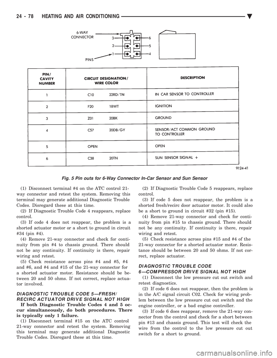
Fig. 5 Pin outs for 6-Way Connector In-Car Sensor and Sun Sensor
24 - 78 HEATING AND AIR CONDITIONING Ä
Page 2414 of 2438

FOREWORD
The information contained in this Service Manual has been prepared for the professional automotive
technician involved in daily repair operations. Information describing the operation and use of standard and
optional equipment is included in the Owner's Manual provided with the vehicle.
These diagrams contain the latest information at the time of publication and incorporate the wiring schematic
for the basic vehicle and available optional equipment.
The diagrams are grouped by body type and sales division. The body codes are explained in the General
Information section. (ExampleÐAP-D, P=Shadow, Sundance). To locate a system or component refer to the black
index tabs on the next page. The tab will assist you in locating the desired area of the manual.
An alphabetical index is provided at the beginning of each section to help you in locating a system or
component. All diagrams are identified by SHEET NUMBER which is found in the lower right- or left-hand corner
of the page.
A Service Manual Comment form is included at the rear of this manual. Use the form to provide Chrysler
Corporation with your comments and suggestions.
Chrysler Corporation reserves the right to change testing procedures, specifications, diagnosis, repair
methods, or vehicle wiring at any time without prior notice or incurring obligation.
NOTE: The acronyms, terminology and nomenclature used to identify emissions related components in this
manual may have changed from prior publications. These new terms are in compliance with S.A.E.
recommended practice J1930. This terminology standard (J1930) is required to comply with the 1993
California Air Research Board (CARB) requirements.
NEXT PAGE ©
Page 2415 of 2438

GROUP TAB LOCATOR
ENGINE, CHASSIS BODY
ELECTRICAL, FUEL EMISSION SYSTEMS
WIRING DIAGRAMS
SUPPLEMENTS
Service Manual Comment Forms (Rear of Manual)