engine coolant CHEVROLET DYNASTY 1993 Repair Manual
[x] Cancel search | Manufacturer: CHEVROLET, Model Year: 1993, Model line: DYNASTY, Model: CHEVROLET DYNASTY 1993Pages: 2438, PDF Size: 74.98 MB
Page 1468 of 2438
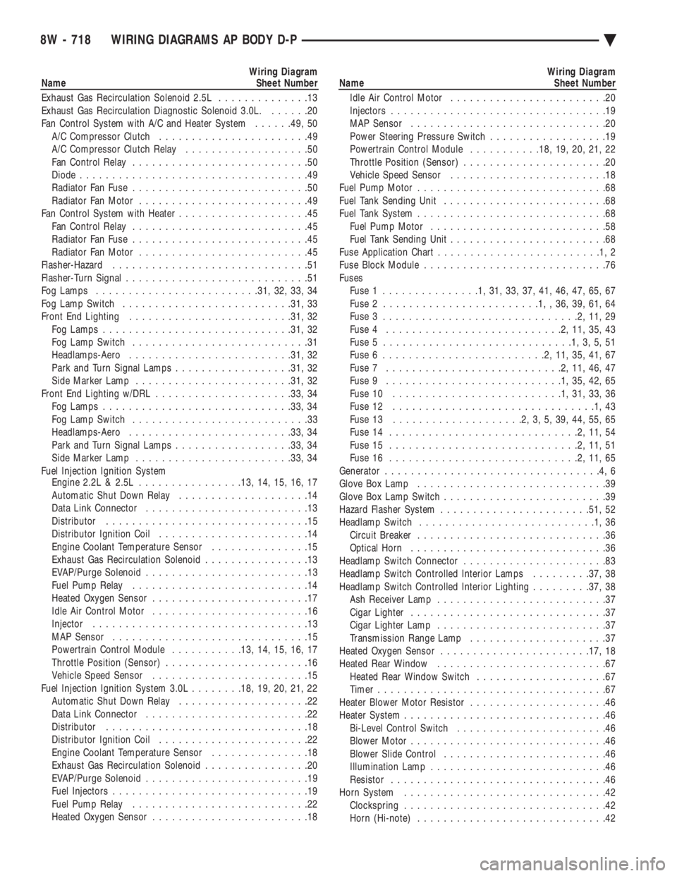
Wiring Diagram
Name Sheet Number
Exhaust Gas Recirculation Solenoid 2.5L ..............13
Exhaust Gas Recirculation Diagnostic Solenoid 3.0L. ......20
Fan Control System with A/C and Heater System ......49, 50
A/C Compressor Clutch .......................49
A/C Compressor Clutch Relay ...................50
Fan Control Relay ...........................50
Diode ...................................49
Radiator Fan Fuse ...........................50
Radiator Fan Motor ..........................49
Fan Control System with Heater ....................45
Fan Control Relay ...........................45
Radiator Fan Fuse ...........................45
Radiator Fan Motor ..........................45
Flasher-Hazard ..............................51
Flasher-Turn Signal ............................51
Fog Lamps ........................ .31, 32, 33, 34
Fog Lamp Switch ......................... .31, 33
Front End Lighting ........................ .31, 32
Fog Lamps ............................ .31, 32
Fog Lamp Switch ...........................31
Headlamps-Aero ........................ .31, 32
Park and Turn Signal Lamps ..................31, 32
Side Marker Lamp ....................... .31, 32
Front End Lighting w/DRL .................... .33, 34
Fog Lamps ............................ .33, 34
Fog Lamp Switch ...........................33
Headlamps-Aero ........................ .33, 34
Park and Turn Signal Lamps ..................33, 34
Side Marker Lamp ....................... .33, 34
Fuel Injection Ignition System Engine 2.2L & 2.5L ............... .13, 14, 15, 16, 17
Automatic Shut Down Relay ....................14
Data Link Connector .........................13
Distributor ...............................15
Distributor Ignition Coil .......................14
Engine Coolant Temperature Sensor ...............15
Exhaust Gas Recirculation Solenoid ................13
EVAP/Purge Solenoid .........................13
Fuel Pump Relay ...........................14
Heated Oxygen Sensor ........................17
Idle Air Control Motor ........................16
Injector .................................13
MAP Sensor ..............................15
Powertrain Control Module ...........13, 14, 15, 16, 17
Throttle Position (Sensor) ......................16
Vehicle Speed Sensor ........................15
Fuel Injection Ignition System 3.0L ........18, 19, 20, 21, 22
Automatic Shut Down Relay ....................22
Data Link Connector .........................22
Distributor ...............................18
Distributor Ignition Coil .......................22
Engine Coolant Temperature Sensor ...............18
Exhaust Gas Recirculation Solenoid ................20
EVAP/Purge Solenoid .........................19
Fuel Injectors ..............................19
Fuel Pump Relay ...........................22
Heated Oxygen Sensor ........................18Wiring Diagram
Name Sheet Number
Idle Air Control Motor ........................20
Injectors .................................19
MAP Sensor ..............................20
Power Steering Pressure Switch ..................19
Powertrain Control Module ...........18, 19, 20, 21, 22
Throttle Position (Sensor) ......................20
Vehicle Speed Sensor ........................18
Fuel Pump Motor .............................68
Fuel Tank Sending Unit .........................68
Fuel Tank System .............................68
Fuel Pump Motor ...........................58
Fuel Tank Sending Unit ........................68
Fuse Application Char t.........................1,2
Fuse Block Module ............................76
Fuses Fuse 1 ...............1,31,33,37,41,46,47,65,67
Fuse 2 ........................1,,36,39,61,64
Fuse 3 ..............................2,11,29
Fuse 4 ...........................2,11,35,43
Fuse 5 .............................1,3,5,51
Fuse 6 .........................2,11,35,41,67
Fuse 7 ...........................2,11,46,47
Fuse 9 ...........................1,35,42,65
Fuse 10 ..........................1,31,33,36
Fuse 12 ...............................1,43
Fuse 13 ....................2,3,5,39,44,55,65
Fuse 14 .............................2,11,54
Fuse 15 .............................2,11,51
Fuse 16 .............................2,11,65
Generator .................................4,6
Glove Box Lamp .............................39
Glove Box Lamp Switch .........................39
Hazard Flasher System ...................... .51, 52
Headlamp Switch ...........................1,36
Circuit Breaker .............................36
Optical Horn ..............................36
Headlamp Switch Connector ......................83
Headlamp Switch Controlled Interior Lamps .........37, 38
Headlamp Switch Controlled Interior Lighting .........37, 38
Ash Receiver Lamp ..........................37
Cigar Lighter ..............................37
Cigar Lighter Lamp ..........................37
Transmission Range Lamp .....................37
Heated Oxygen Sensor ...................... .17, 18
Heated Rear Window ..........................67
Heated Rear Window Switch ....................67
Timer ...................................67
Heater Blower Motor Resistor .....................46
Heater System ...............................46
Bi-Level Control Switch .......................46
Blower Motor ..............................46
Blower Slide Control .........................46
Illumination Lamp ...........................46
Resistor .................................46
Horn System ...............................42
Clockspring ...............................42
Horn (Hi-note) .............................42
8W - 718 WIRING DIAGRAMS AP BODY D-P Ä
Page 1470 of 2438
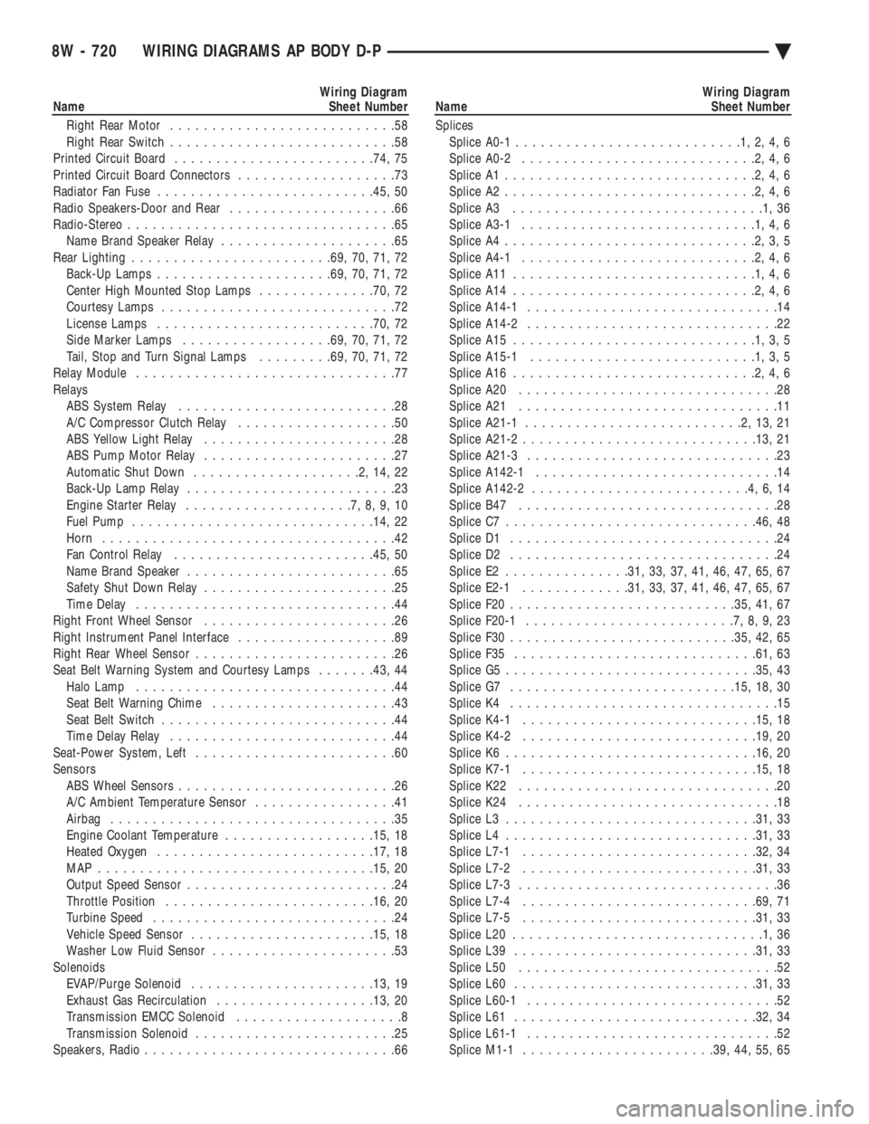
Wiring Diagram
Name Sheet Number
Right Rear Motor ...........................58
Right Rear Switch ...........................58
Printed Circuit Board ....................... .74, 75
Printed Circuit Board Connectors ...................73
Radiator Fan Fuse ......................... .45, 50
Radio Speakers-Door and Rear ....................66
Radio-Stereo ................................65
Name Brand Speaker Relay .....................65
Rear Lighting ....................... .69, 70, 71, 72
Back-Up Lamps .................... .69, 70, 71, 72
Center High Mounted Stop Lamps ..............70, 72
Courtesy Lamps ............................72
License Lamps ......................... .70, 72
Side Marker Lamps ................. .69, 70, 71, 72
Tail, Stop and Turn Signal Lamps .........69, 70, 71, 72
Relay Module ...............................77
Relays ABS System Relay ..........................28
A/C Compressor Clutch Relay ...................50
ABS Yellow Light Relay .......................28
ABS Pump Motor Relay .......................27
Automatic Shut Down ....................2,14,22
Back-Up Lamp Relay .........................23
Engine Starter Relay ....................7,8,9,10
Fuel Pump ............................ .14, 22
Horn ...................................42
Fan Control Relay ....................... .45, 50
Name Brand Speaker .........................65
Safety Shut Down Relay .......................25
Time Delay ...............................44
Right Front Wheel Sensor .......................26
Right Instrument Panel Interface ...................89
Right Rear Wheel Sensor ........................26
Seat Belt Warning System and Courtesy Lamps .......43, 44
Halo Lamp ...............................44
Seat Belt Warning Chime ......................43
Seat Belt Switch ............................44
Time Delay Relay ...........................44
Seat-Power System, Left ........................60
Sensors ABS Wheel Sensors ..........................26
A/C Ambient Temperature Sensor .................41
Airbag ..................................35
Engine Coolant Temperature ..................15, 18
Heated Oxygen ......................... .17, 18
MAP ................................ .15, 20
Output Speed Sensor .........................24
Throttle Position ........................ .16, 20
Turbine Speed .............................24
Vehicle Speed Sensor ..................... .15, 18
Washer Low Fluid Sensor ......................53
Solenoids EVAP/Purge Solenoid ..................... .13, 19
Exhaust Gas Recirculation .................. .13, 20
Transmission EMCC Solenoid ....................8
Transmission Solenoid ........................25
Speakers, Radio ..............................66Wiring Diagram
Name Sheet Number
Splices Splice A0-1 ...........................1,2,4,6
Splice A0-2 ............................2,4,6
Splice A1 ..............................2,4,6
Splice A2 ..............................2,4,6
Splice A3 ..............................1,36
Splice A3-1 ............................1,4,6
Splice A4 ..............................2,3,5
Splice A4-1 ............................2,4,6
Splice A11 .............................1,4,6
Splice A14 .............................2,4,6
Splice A14-1 ..............................14
Splice A14-2 ..............................22
Splice A15 .............................1,3,5
Splice A15-1 ...........................1,3,5
Splice A16 .............................2,4,6
Splice A20 ...............................28
Splice A21 ...............................11
Splice A21-1 ..........................2,13,21
Splice A21-2 ........................... .13, 21
Splice A21-3 ..............................23
Splice A142-1 .............................14
Splice A142-2 ..........................4,6,14
Splice B47 ...............................28
Splice C7 ............................. .46, 48
Splice D1 ................................24
Splice D2 ................................24
Splice E2 .............. .31, 33, 37, 41, 46, 47, 65, 67
Splice E2-1 ............ .31, 33, 37, 41, 46, 47, 65, 67
Splice F20 .......................... .35, 41, 67
Splice F20-1 .........................7,8,9,23
Splice F30 .......................... .35, 42, 65
Splice F35 ............................ .61, 63
Splice G5 ............................. .35, 43
Splice G7 .......................... .15, 18, 30
Splice K4 ................................15
Splice K4-1 ........................... .15, 18
Splice K4-2 ........................... .19, 20
Splice K6 ............................. .16, 20
Splice K7-1 ........................... .15, 18
Splice K22 ...............................20
Splice K24 ...............................18
Splice L3 ............................. .31, 33
Splice L4 ............................. .31, 33
Splice L7-1 ........................... .32, 34
Splice L7-2 ........................... .31, 33
Splice L7-3 ...............................36
Splice L7-4 ........................... .69, 71
Splice L7-5 ........................... .31, 33
Splice L20 ..............................1,36
Splice L39 ............................ .31, 33
Splice L50 ...............................52
Splice L60 ............................ .31, 33
Splice L60-1 ..............................52
Splice L61 ............................ .32, 34
Splice L61-1 ..............................52
Splice M1-1 ...................... .39, 44, 55, 65
8W - 720 WIRING DIAGRAMS AP BODY D-P Ä
Page 1575 of 2438

Flexible fuel vehicles can operate on a mixture of
up to 85 percent methanol, 15 percent unleaded gas-
oline. These vehicles also operate on mixtures con-
taining a lower percentage of methanol or just pure
unleaded gasoline. Engine components which are required for safe op-
eration using fuel containing methanol alcohol are
identified by a standard green color and/or display
the statement methanol compatible imprinted on the
component. To ensure continued safe operation, these
components must be serviced only with genuine MO-
PAR replacement parts. Methanol compatible parts for the 2.5L FFV (Flex-
ible Fuel Vehicle) engine include, but are not limited
to; the valve stem oil seals, all piston rings, the oil
fill cap, the fuel injectors, fuel rail, fuel pressure reg-
ulator, hoses and the vacuum control harness hose. BLOCK: All four cylinder cast iron blocks have
cast-in recesses in the bottom of each cylinder bore to
provide connecting rod clearance; especially needed
for 2.5L engines. The bores are also siamese to min-
imize engine length. A coolant passage is drilled
cross-ways through the siamese section to enhance
between the bore cooling on some engine types. A
partial open deck is used for cooling and weight re-
duction with oil filter, water pump, and distributor
mounting bosses molded into the front (radiator side)
of the block. Nominal wall thickness is 4.5 mm. Five
main bearing bulkheads and a block skirt extending
3 mm below the crankshaft center line add to the
blocks high rigidity with light weight. CRANKSHAFT: A nodular cast iron crankshaft is
used in TBI engines. A forged steel crankshaft is
used in the Turbo III engine. All engines have 5 main bearings, with number 3 flanged to control
thrust. The 60 mm diameter main and 50 mm diam-
eter crank pin journals (all) have undercut radiuses
fillets that are deep rolled for added strength. To op-
timize bearing loading 4 counterweights are used.
Hydrodynamic seals (installed in diecast aluminum
retainers) provide end sealing, where the crankshaft
exits the block. Anaerobic gasket material is used for
retainer-to-block sealing. No vibration damper is
used. A sintered iron (TBI engine and steel billet
Turbo III engines) timing belt sprocket is mounted
on the crankshaft nose. This sprocket provides mo-
tive power; via timing belt to the camshaft and inter-
mediate shaft sprockets (also sintered iron (TBI
engine and steel billet Turbo III engines) providing
timed valve, distributor, and oil pump actuation. PISTONS: Some Chrysler pistons have cast-in
steel struts at the pin bosses for autothermic control.
All 2.2L and 2.5L piston tops have cuts to provide
valve clearance. Some pistons are dished to provide
various compression ratios. Standard 2.2L and 2.5L
engines are designed for 9.5:1 and 8.9:1 compression
ratios respectively. The 2.5L piston is dished and is a
lightweight design to enhance engine smoothness.
The 2.2L turbo III uses dished pistons providing a
8.3:1 compression ratio. All standard 2.2/2.5L and
2.5L FFV engines use pressed-in piston pins to at-
tach forged steel connecting rods, 2.2L turbo III en-
gine uses a full floating piston pin and connecting
rod assembly. PISTONS RINGS: The 2.2/2.5L engines share
common piston rings throughout, including molybde-
num filled top ring for reliable compression sealing
and a tapered faced intermediate ring for additional
cylinder pressure control. The 2.5L FFV engine fea-
ture all chrome rings for enhanced long term dura-
bility under multi-fueled conditions. CYLINDER HEAD: The cylinder head is cast alu-
minum with in-line valves. The 2.2/2.5L and 2.5L
FFV valves are arranged with alternating exhaust
and intake. The intake and exhaust ports are located
in the rearward, facing side of the head. The Turbo
III valves are arranged in two inline banks, with the
ports of the bank of two intake valves per cylinder
facing toward the radiator side of engine and ports of
the bank of two exhaust valve per cylinder facing to-
ward the dash panel. The intake ports feed fast-burn
design combustion chambers (2.2/2.5L and 2.5L FFV
only) with the spark plug located close to the center
line of the combustion chamber for optimum effi-
ciency. An integral oil gallery within the cylinder
head supplies oil to the hydraulic lash adjusters,
camshaft, and valve mechanisms. CAMSHAFT: The nodular iron camshaft has five
bearing journals (2.2/2.5L and 2.5L FFV). The Turbo
III employs dual camshafts that have nine bearing
journals. Flanges at the rear journal control cam-
Fig. 1 Engine Identification
Ä 2.2/2.5L ENGINE 9 - 9
Page 1635 of 2438
LEFT SIDE MOUNT
(1) Raise vehicle on hoist and remove left front
wheel. (2) Remove inter splash shield.
(3) Support the transmission with a transmission
jack. (4) Remove the insulator thru bolt from the mount.
(5) Remove the transmission mount fasteners and
remove mount. (6) Reverse removal procedure for installation. En-
sure that the slide tube is seated into the rail
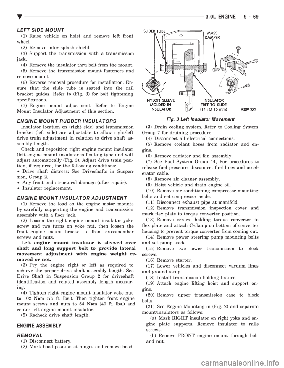
bracket guides. Refer to (Fig. 3) for bolt tightening
specifications. (7) Engine mount adjustment, Refer to Engine
Mount Insulator Adjustment of this section.
ENGINE MOUNT RUBBER INSULATORS
Insulator location on (right side) and transmission
bracket (left side) are adjustable to allow right/left
drive train adjustment in relation to drive shaft as-
sembly length. Check and reposition right engine mount insulator
(left engine mount insulator is floating type and will
adjust automatically (Fig. 3). Adjust drive train posi-
tion, if required, for the following conditions:
² Drive shaft distress: See Driveshafts in Suspen-
sion, Group 2.
² Any front end structural damage (after repair).
² Insulator replacement.
ENGINE MOUNT INSULATOR ADJUSTMENT
(1) Remove the load on the engine motor mounts
by carefully supporting the engine and transmission
assembly with a floor jack. (2) Loosen the right engine mount insulator yoke
screw and two turns on yoke nut, then loosen the
front engine mount bracket to front crossmember
screws and nuts. Left engine mount insulator is sleeved over
shaft and long support bolt to provide lateral
movement adjustment with engine weight re-
moved or not. (3) Pry the engine right or left as required to
achieve the proper drive shaft assembly length. See
Drive Shaft in Suspension Group 2 for driveshaft
identification and related assembly length measur-
ing. (4) Tighten right engine mount insulator yoke nut
to 102 N Im (75 ft. lbs.). Then tighten front engine
mount screws and nuts to 54 N Im (40 ft. lbs.) and
center left engine mount insulator. (5) Recheck drive shaft length.
ENGINE ASSEMBLY
REMOVAL
(1) Disconnect battery.
(2) Mark hood position at hinges and remove hood. (3) Drain cooling system. Refer to Cooling System
Group 7 for draining procedure. (4) Disconnect all electrical connections.
(5) Remove coolant hoses from radiator and en-
gine. (6) Remove radiator and fan assembly.
(7) See Fuel System Group 14, For procedures to
release fuel pressure, disconnect fuel lines and accel-
erator cable. (8) Remove air cleaner assembly.
(9) Hoist vehicle and drain engine oil.
(10) Remove air conditioning compressor mounting
bolts and set compressor aside. (11) Disconnect exhaust pipe at manifold.
(12) Remove transmission inspection cover and
mark flex plate to torque converter position. (13) Remove screws holding torque converter to
flex plate and attach C-clamp on bottom of converter
housing to prevent torque converter from coming out. (14) Remove power steering pump mounting bolts
and set pump aside. (15) Remove two lower transmission to block
screws. (16) Remove starter.
(17) Lower vehicles and disconnect vacuum lines
and ground strap. (18) Install transmission holding fixture.
(19) Attach engine lifting hoist and support en-
gine. (20) Remove upper transmission case to block
bolts. (21) See Engine Mounting in (Fig. 2) and separate
mount/insulators as follows: (a) Mark RIGHT insulator on right yoke and en-
gine plate supports. Remove insulator to rails
screws. (b) Remove FRONT engine mount through bolt
and nut.
Fig. 3 Left Insulator Movement
Ä 3.0L ENGINE 9 - 69
Page 1667 of 2438
(2) Loosen the right engine mount insulator yoke
screw and 2 turns on yoke nut, then loosen the front
engine mount bracket to front crossmember screws and
nuts. Left engine mount insulator is sleeved over
shaft and long support bolt to provide lateral
movement adjustment with engine weight re-
moved or not. (3) Pry the engine right or left as required to achieve
the proper drive shaft assembly length. See Drive
Shaft in Suspension Group 2 for driveshaft identifica-
tion and related assembly length measuring. (4) Tighten right engine mount insulator yoke nut to
102 N Im (75 ft. lbs.). Then tighten front engine mount
screws and nuts to 54 N Im (40 ft. lbs.) and center left
engine mount insulator. (5) Recheck drive shaft length.
ENGINE ASSEMBLY
REMOVAL
(1) Disconnect battery.
(2) Mark hood position at hinges and remove hood.
(3) Drain cooling system. Refer to Cooling System,
Group 7 for procedure. (4) Disconnect all electrical connections.
(5) Remove coolant hoses from radiator and engine.
(6) Remove radiator and fan assembly.
(7) See Fuel System, Group 14, to release fuel pres-
sure. Disconnect fuel lines and accelerator cable. (8) Remove air cleaner assembly.
(9) Hoist vehicle and drain engine oil.
(10) Remove air conditioning compressor mounting
bolts and set compressor aside. (11) Disconnect exhaust pipe at manifold.
(12) Remove transmission inspection cover and
mark flex plate to torque converter position. For disas-
sembly procedure for the all wheel drive vehicle refer to
Group 21 Transaxle. (13) Remove screws holding torque converter to
flex plate and attach C-clamp on bottom of converter
housing to prevent torque converter from counting
out. (14) Remove power steering pump mounting bolts
and set pump aside. (15) Remove two lower transmission to block
screws. (16) Remove starter.
(17) Lower vehicles and disconnect vacuum lines
and ground strap. (18) Install transmission holding fixture.
(19) Attach engine lifting hoist and support en-
gine. (20) Remove upper transmission case to block
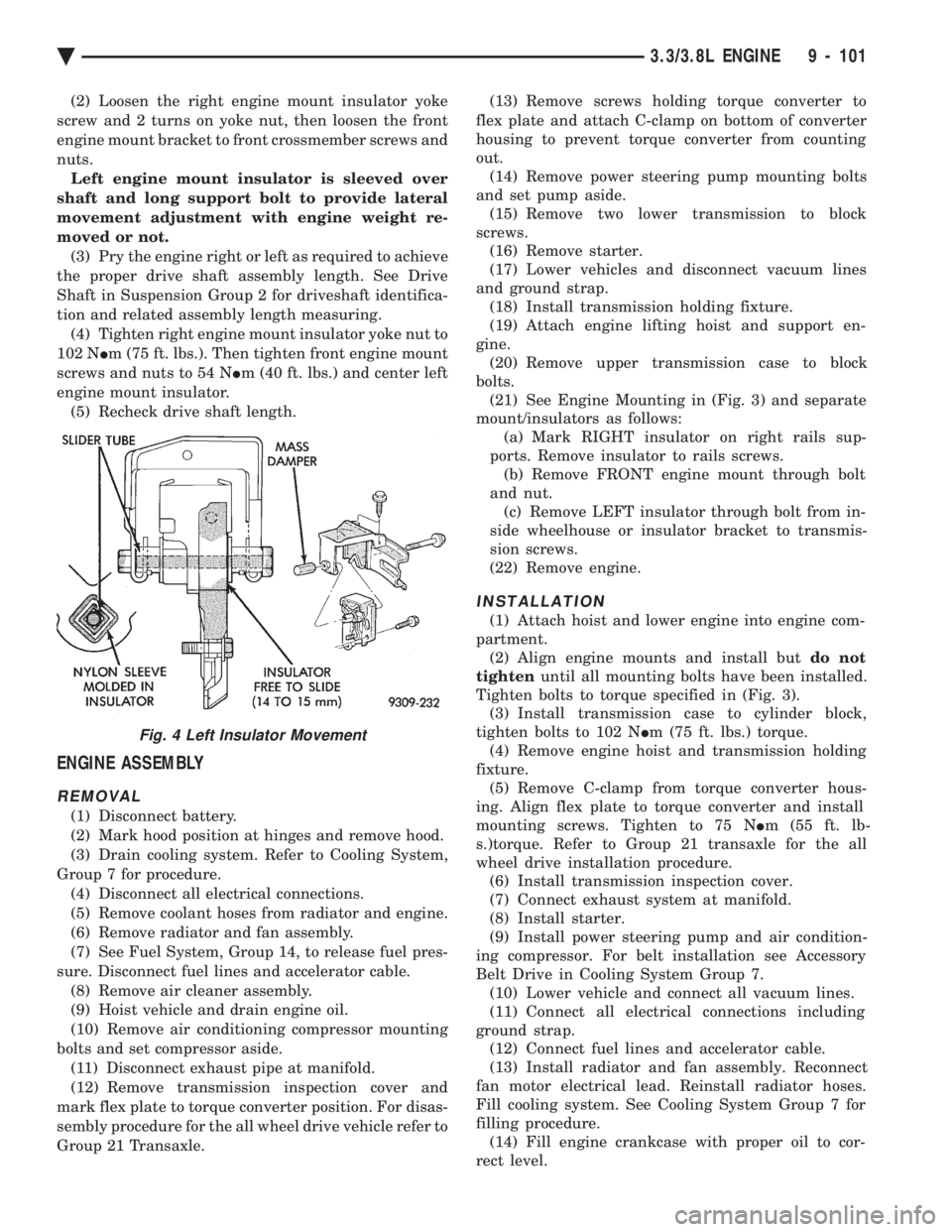
bolts. (21) See Engine Mounting in (Fig. 3) and separate
mount/insulators as follows: (a) Mark RIGHT insulator on right rails sup-
ports. Remove insulator to rails screws. (b) Remove FRONT engine mount through bolt
and nut. (c) Remove LEFT insulator through bolt from in-
side wheelhouse or insulator bracket to transmis-
sion screws.
(22) Remove engine.
INSTALLATION
(1) Attach hoist and lower engine into engine com-
partment. (2) Align engine mounts and install but do not
tighten until all mounting bolts have been installed.
Tighten bolts to torque specified in (Fig. 3). (3) Install transmission case to cylinder block,
tighten bolts to 102 N Im (75 ft. lbs.) torque.
(4) Remove engine hoist and transmission holding
fixture. (5) Remove C-clamp from torque converter hous-
ing. Align flex plate to torque converter and install
mounting screws. Tighten to 75 N Im (55 ft. lb-
s.)torque. Refer to Group 21 transaxle for the all
wheel drive installation procedure. (6) Install transmission inspection cover.
(7) Connect exhaust system at manifold.
(8) Install starter.
(9) Install power steering pump and air condition-
ing compressor. For belt installation see Accessory
Belt Drive in Cooling System Group 7. (10) Lower vehicle and connect all vacuum lines.
(11) Connect all electrical connections including
ground strap. (12) Connect fuel lines and accelerator cable.
(13) Install radiator and fan assembly. Reconnect
fan motor electrical lead. Reinstall radiator hoses.
Fill cooling system. See Cooling System Group 7 for
filling procedure. (14) Fill engine crankcase with proper oil to cor-
rect level.
Fig. 4 Left Insulator Movement
Ä 3.3/3.8L ENGINE 9 - 101
Page 1708 of 2438
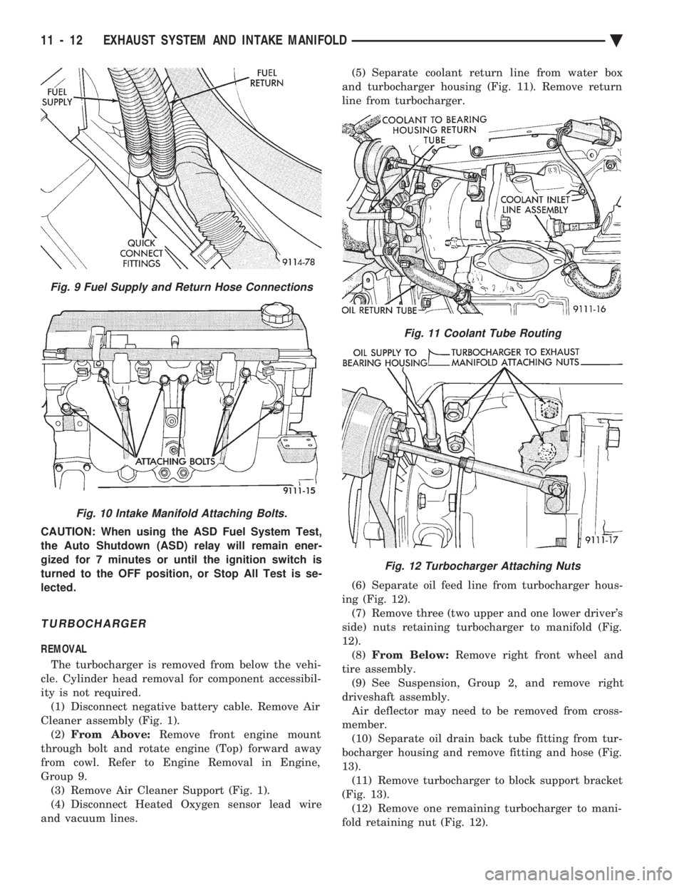
CAUTION: When using the ASD Fuel System Test,
the Auto Shutdown (ASD) relay will remain ener-
gized for 7 minutes or until the ignition switch is
turned to the OFF position, or Stop All Test is se-
lected.
TURBOCHARGER
REMOVAL
The turbocharger is removed from below the vehi-
cle. Cylinder head removal for component accessibil-
ity is not required. (1) Disconnect negative battery cable. Remove Air
Cleaner assembly (Fig. 1). (2) From Above: Remove front engine mount
through bolt and rotate engine (Top) forward away
from cowl. Refer to Engine Removal in Engine,
Group 9. (3) Remove Air Cleaner Support (Fig. 1).
(4) Disconnect Heated Oxygen sensor lead wire
and vacuum lines. (5) Separate coolant return line from water box
and turbocharger housing (Fig. 11). Remove return
line from turbocharger.
(6) Separate oil feed line from turbocharger hous-
ing (Fig. 12). (7) Remove three (two upper and one lower driver's
side) nuts retaining turbocharger to manifold (Fig.
12). (8) From Below: Remove right front wheel and
tire assembly. (9) See Suspension, Group 2, and remove right
driveshaft assembly. Air deflector may need to be removed from cross-
member. (10) Separate oil drain back tube fitting from tur-
bocharger housing and remove fitting and hose (Fig.
13). (11) Remove turbocharger to block support bracket
(Fig. 13). (12) Remove one remaining turbocharger to mani-
fold retaining nut (Fig. 12).
Fig. 11 Coolant Tube Routing
Fig. 12 Turbocharger Attaching Nuts
Fig. 9 Fuel Supply and Return Hose Connections
Fig. 10 Intake Manifold Attaching Bolts.
11 - 12 EXHAUST SYSTEM AND INTAKE MANIFOLD Ä
Page 1709 of 2438
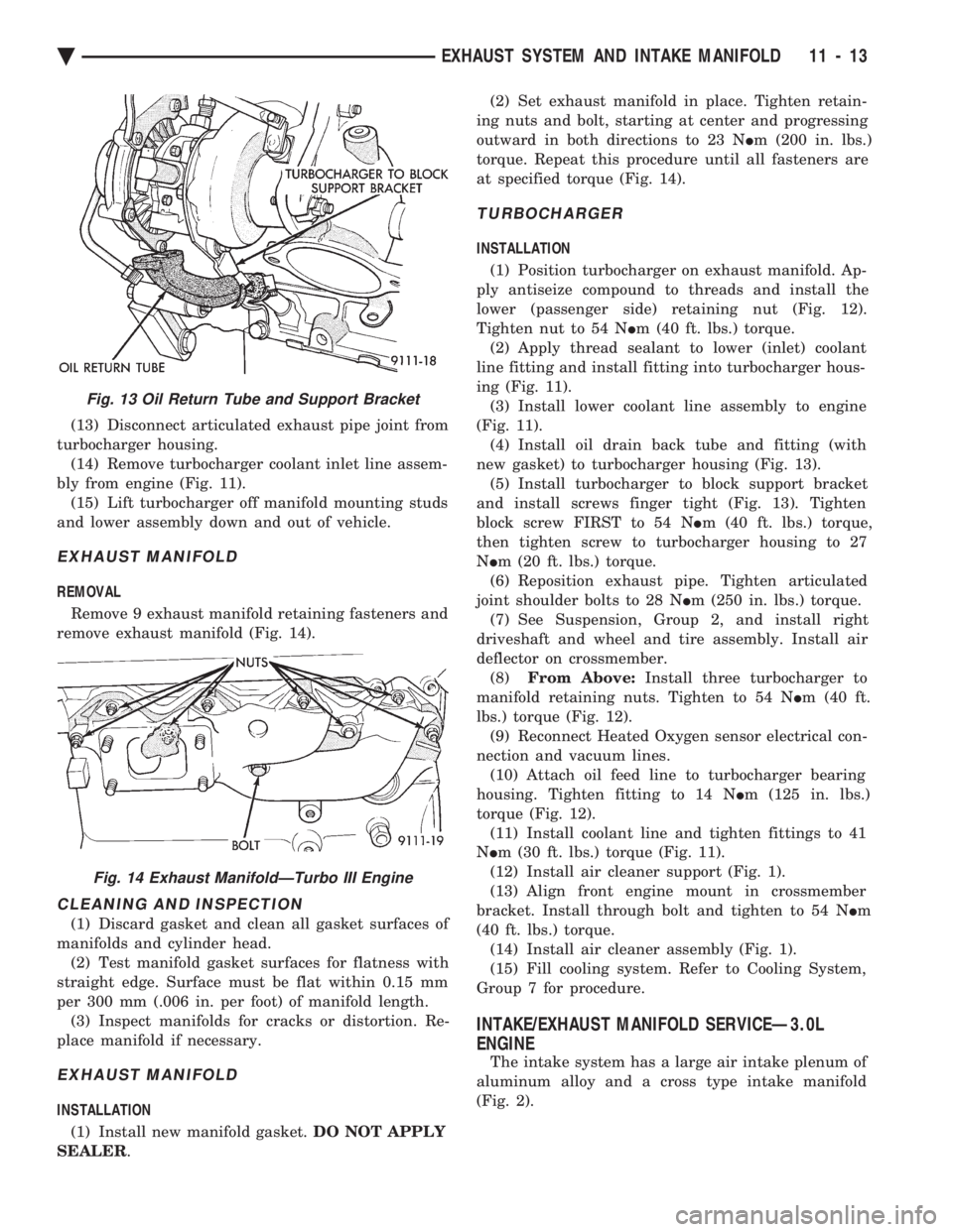
(13) Disconnect articulated exhaust pipe joint from
turbocharger housing. (14) Remove turbocharger coolant inlet line assem-
bly from engine (Fig. 11). (15) Lift turbocharger off manifold mounting studs
and lower assembly down and out of vehicle.
EXHAUST MANIFOLD
REMOVAL
Remove 9 exhaust manifold retaining fasteners and
remove exhaust manifold (Fig. 14).
CLEANING AND INSPECTION
(1) Discard gasket and clean all gasket surfaces of
manifolds and cylinder head. (2) Test manifold gasket surfaces for flatness with
straight edge. Surface must be flat within 0.15 mm
per 300 mm (.006 in. per foot) of manifold length. (3) Inspect manifolds for cracks or distortion. Re-
place manifold if necessary.
EXHAUST MANIFOLD
INSTALLATION
(1) Install new manifold gasket. DO NOT APPLY
SEALER . (2) Set exhaust manifold in place. Tighten retain-
ing nuts and bolt, starting at center and progressing
outward in both directions to 23 N Im (200 in. lbs.)
torque. Repeat this procedure until all fasteners are
at specified torque (Fig. 14).
TURBOCHARGER
INSTALLATION
(1) Position turbocharger on exhaust manifold. Ap-
ply antiseize compound to threads and install the
lower (passenger side) retaining nut (Fig. 12).
Tighten nut to 54 N Im (40 ft. lbs.) torque.
(2) Apply thread sealant to lower (inlet) coolant
line fitting and install fitting into turbocharger hous-
ing (Fig. 11). (3) Install lower coolant line assembly to engine
(Fig. 11). (4) Install oil drain back tube and fitting (with
new gasket) to turbocharger housing (Fig. 13). (5) Install turbocharger to block support bracket
and install screws finger tight (Fig. 13). Tighten
block screw FIRST to 54 N Im (40 ft. lbs.) torque,
then tighten screw to turbocharger housing to 27
N Im (20 ft. lbs.) torque.
(6) Reposition exhaust pipe. Tighten articulated
joint shoulder bolts to 28 N Im (250 in. lbs.) torque.
(7) See Suspension, Group 2, and install right
driveshaft and wheel and tire assembly. Install air
deflector on crossmember. (8) From Above: Install three turbocharger to
manifold retaining nuts. Tighten to 54 N Im (40 ft.
lbs.) torque (Fig. 12). (9) Reconnect Heated Oxygen sensor electrical con-
nection and vacuum lines. (10) Attach oil feed line to turbocharger bearing
housing. Tighten fitting to 14 N Im (125 in. lbs.)
torque (Fig. 12). (11) Install coolant line and tighten fittings to 41
N Im (30 ft. lbs.) torque (Fig. 11).
(12) Install air cleaner support (Fig. 1).
(13) Align front engine mount in crossmember
bracket. Install through bolt and tighten to 54 N Im
(40 ft. lbs.) torque. (14) Install air cleaner assembly (Fig. 1).
(15) Fill cooling system. Refer to Cooling System,
Group 7 for procedure.
INTAKE/EXHAUST MANIFOLD SERVICEÐ3.0L
ENGINE
The intake system has a large air intake plenum of
aluminum alloy and a cross type intake manifold
(Fig. 2).
Fig. 13 Oil Return Tube and Support Bracket
Fig. 14 Exhaust ManifoldÐTurbo III Engine
Ä EXHAUST SYSTEM AND INTAKE MANIFOLD 11 - 13
Page 1711 of 2438
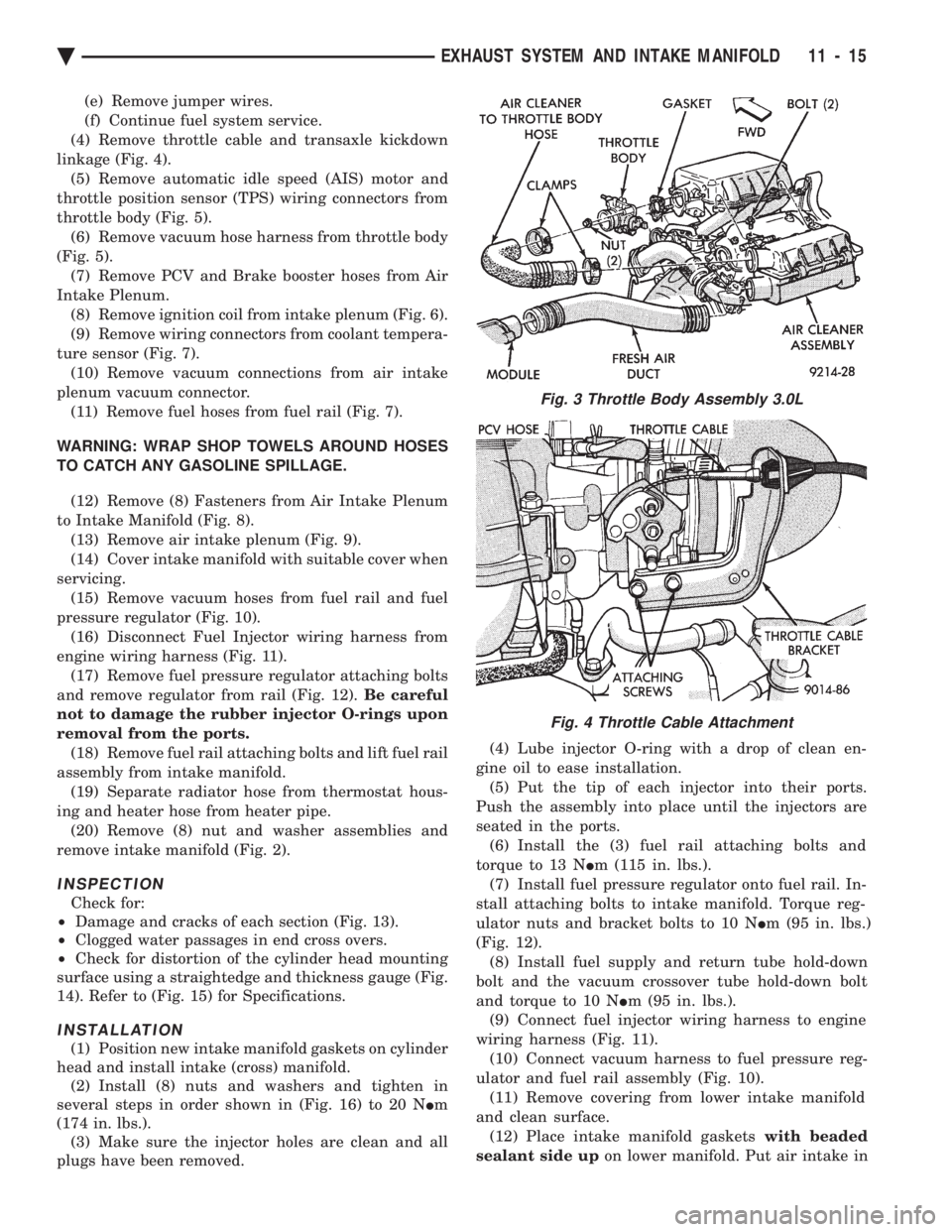
(e) Remove jumper wires.
(f) Continue fuel system service.
(4) Remove throttle cable and transaxle kickdown
linkage (Fig. 4). (5) Remove automatic idle speed (AIS) motor and
throttle position sensor (TPS) wiring connectors from
throttle body (Fig. 5). (6) Remove vacuum hose harness from throttle body
(Fig. 5). (7) Remove PCV and Brake booster hoses from Air
Intake Plenum. (8) Remove ignition coil from intake plenum (Fig. 6).
(9) Remove wiring connectors from coolant tempera-
ture sensor (Fig. 7). (10) Remove vacuum connections from air intake
plenum vacuum connector. (11) Remove fuel hoses from fuel rail (Fig. 7).
WARNING: WRAP SHOP TOWELS AROUND HOSES
TO CATCH ANY GASOLINE SPILLAGE. (12) Remove (8) Fasteners from Air Intake Plenum
to Intake Manifold (Fig. 8). (13) Remove air intake plenum (Fig. 9).
(14) Cover intake manifold with suitable cover when
servicing. (15) Remove vacuum hoses from fuel rail and fuel
pressure regulator (Fig. 10). (16) Disconnect Fuel Injector wiring harness from
engine wiring harness (Fig. 11). (17) Remove fuel pressure regulator attaching bolts
and remove regulator from rail (Fig. 12). Be careful
not to damage the rubber injector O-rings upon
removal from the ports. (18) Remove fuel rail attaching bolts and lift fuel rail
assembly from intake manifold. (19) Separate radiator hose from thermostat hous-
ing and heater hose from heater pipe. (20) Remove (8) nut and washer assemblies and
remove intake manifold (Fig. 2).
INSPECTION
Check for:
² Damage and cracks of each section (Fig. 13).
² Clogged water passages in end cross overs.
² Check for distortion of the cylinder head mounting
surface using a straightedge and thickness gauge (Fig.
14). Refer to (Fig. 15) for Specifications.
INSTALLATION
(1) Position new intake manifold gaskets on cylinder
head and install intake (cross) manifold. (2) Install (8) nuts and washers and tighten in
several steps in order shown in (Fig. 16) to 20 N Im
(174 in. lbs.). (3) Make sure the injector holes are clean and all
plugs have been removed. (4) Lube injector O-ring with a drop of clean en-
gine oil to ease installation. (5) Put the tip of each injector into their ports.
Push the assembly into place until the injectors are
seated in the ports. (6) Install the (3) fuel rail attaching bolts and
torque to 13 N Im (115 in. lbs.).
(7) Install fuel pressure regulator onto fuel rail. In-
stall attaching bolts to intake manifold. Torque reg-
ulator nuts and bracket bolts to 10 N Im (95 in. lbs.)
(Fig. 12). (8) Install fuel supply and return tube hold-down
bolt and the vacuum crossover tube hold-down bolt
and torque to 10 N Im (95 in. lbs.).
(9) Connect fuel injector wiring harness to engine
wiring harness (Fig. 11). (10) Connect vacuum harness to fuel pressure reg-
ulator and fuel rail assembly (Fig. 10). (11) Remove covering from lower intake manifold
and clean surface. (12) Place intake manifold gaskets with beaded
sealant side up on lower manifold. Put air intake in
Fig. 3 Throttle Body Assembly 3.0L
Fig. 4 Throttle Cable Attachment
Ä EXHAUST SYSTEM AND INTAKE MANIFOLD 11 - 15
Page 1717 of 2438
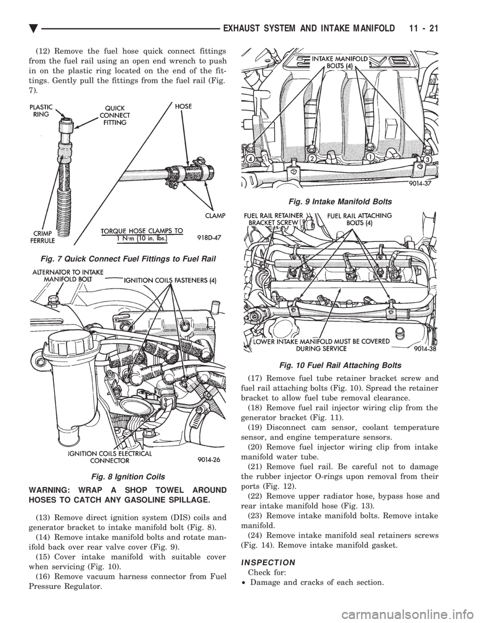
(12) Remove the fuel hose quick connect fittings
from the fuel rail using an open end wrench to push
in on the plastic ring located on the end of the fit-
tings. Gently pull the fittings from the fuel rail (Fig.
7).
WARNING: WRAP A SHOP TOWEL AROUND
HOSES TO CATCH ANY GASOLINE SPILLAGE.
(13) Remove direct ignition system (DIS) coils and
generator bracket to intake manifold bolt (Fig. 8). (14) Remove intake manifold bolts and rotate man-
ifold back over rear valve cover (Fig. 9). (15) Cover intake manifold with suitable cover
when servicing (Fig. 10). (16) Remove vacuum harness connector from Fuel
Pressure Regulator. (17) Remove fuel tube retainer bracket screw and
fuel rail attaching bolts (Fig. 10). Spread the retainer
bracket to allow fuel tube removal clearance. (18) Remove fuel rail injector wiring clip from the
generator bracket (Fig. 11). (19) Disconnect cam sensor, coolant temperature
sensor, and engine temperature sensors. (20) Remove fuel injector wiring clip from intake
manifold water tube. (21) Remove fuel rail. Be careful not to damage
the rubber injector O-rings upon removal from their
ports (Fig. 12). (22) Remove upper radiator hose, bypass hose and
rear intake manifold hose (Fig. 13). (23) Remove intake manifold bolts. Remove intake
manifold. (24) Remove intake manifold seal retainers screws
(Fig. 14). Remove intake manifold gasket.
INSPECTION
Check for:
² Damage and cracks of each section.
Fig. 7 Quick Connect Fuel Fittings to Fuel Rail
Fig. 8 Ignition Coils
Fig. 9 Intake Manifold Bolts
Fig. 10 Fuel Rail Attaching Bolts
Ä EXHAUST SYSTEM AND INTAKE MANIFOLD 11 - 21
Page 1719 of 2438
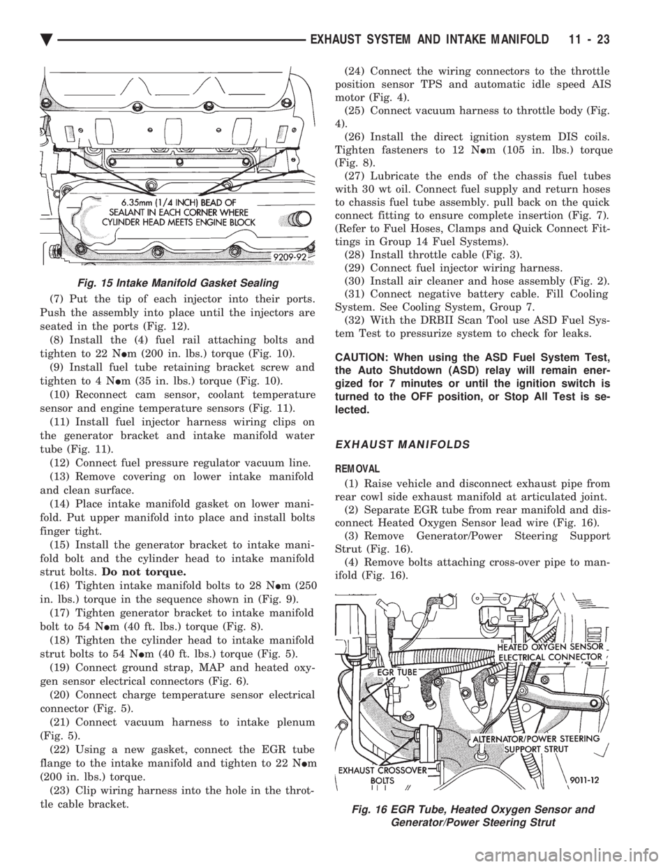
(7) Put the tip of each injector into their ports.
Push the assembly into place until the injectors are
seated in the ports (Fig. 12). (8) Install the (4) fuel rail attaching bolts and
tighten to 22 N Im (200 in. lbs.) torque (Fig. 10).
(9) Install fuel tube retaining bracket screw and
tighten to 4 N Im (35 in. lbs.) torque (Fig. 10).
(10) Reconnect cam sensor, coolant temperature
sensor and engine temperature sensors (Fig. 11). (11) Install fuel injector harness wiring clips on
the generator bracket and intake manifold water
tube (Fig. 11). (12) Connect fuel pressure regulator vacuum line.
(13) Remove covering on lower intake manifold
and clean surface. (14) Place intake manifold gasket on lower mani-
fold. Put upper manifold into place and install bolts
finger tight. (15) Install the generator bracket to intake mani-
fold bolt and the cylinder head to intake manifold
strut bolts. Do not torque.
(16) Tighten intake manifold bolts to 28 N Im (250
in. lbs.) torque in the sequence shown in (Fig. 9). (17) Tighten generator bracket to intake manifold
bolt to 54 N Im (40 ft. lbs.) torque (Fig. 8).
(18) Tighten the cylinder head to intake manifold
strut bolts to 54 N Im (40 ft. lbs.) torque (Fig. 5).
(19) Connect ground strap, MAP and heated oxy-
gen sensor electrical connectors (Fig. 6). (20) Connect charge temperature sensor electrical
connector (Fig. 5). (21) Connect vacuum harness to intake plenum
(Fig. 5). (22) Using a new gasket, connect the EGR tube
flange to the intake manifold and tighten to 22 N Im
(200 in. lbs.) torque. (23) Clip wiring harness into the hole in the throt-
tle cable bracket. (24) Connect the wiring connectors to the throttle
position sensor TPS and automatic idle speed AIS
motor (Fig. 4). (25) Connect vacuum harness to throttle body (Fig.
4). (26) Install the direct ignition system DIS coils.
Tighten fasteners to 12 N Im (105 in. lbs.) torque
(Fig. 8). (27) Lubricate the ends of the chassis fuel tubes
with 30 wt oil. Connect fuel supply and return hoses
to chassis fuel tube assembly. pull back on the quick
connect fitting to ensure complete insertion (Fig. 7).
(Refer to Fuel Hoses, Clamps and Quick Connect Fit-
tings in Group 14 Fuel Systems). (28) Install throttle cable (Fig. 3).
(29) Connect fuel injector wiring harness.
(30) Install air cleaner and hose assembly (Fig. 2).
(31) Connect negative battery cable. Fill Cooling
System. See Cooling System, Group 7. (32) With the DRBII Scan Tool use ASD Fuel Sys-
tem Test to pressurize system to check for leaks.
CAUTION: When using the ASD Fuel System Test,
the Auto Shutdown (ASD) relay will remain ener-
gized for 7 minutes or until the ignition switch is
turned to the OFF position, or Stop All Test is se-
lected.
EXHAUST MANIFOLDS
REMOVAL
(1) Raise vehicle and disconnect exhaust pipe from
rear cowl side exhaust manifold at articulated joint. (2) Separate EGR tube from rear manifold and dis-
connect Heated Oxygen Sensor lead wire (Fig. 16). (3) Remove Generator/Power Steering Support
Strut (Fig. 16). (4) Remove bolts attaching cross-over pipe to man-
ifold (Fig. 16).
Fig. 15 Intake Manifold Gasket Sealing
Fig. 16 EGR Tube, Heated Oxygen Sensor and Generator/Power Steering Strut
Ä EXHAUST SYSTEM AND INTAKE MANIFOLD 11 - 23