engine coolant CHEVROLET DYNASTY 1993 Workshop Manual
[x] Cancel search | Manufacturer: CHEVROLET, Model Year: 1993, Model line: DYNASTY, Model: CHEVROLET DYNASTY 1993Pages: 2438, PDF Size: 74.98 MB
Page 477 of 2438
2.2L TURBO III, 3.3L AND 3.8L IGNITION SYSTEMÐDIAGNOSTIC PROCEDURES INDEX
page page
Check Coil TestÐ3.3L and 3.8L Engines ...... 36
Check Coil TestÐTurbo III Engine ........... 35
Coolant Temperature Sensor Test ............ 38
Crankshaft Position Sensor and Camshaft Position Sensor Tests .......................... 38 Failure to Start Test
...................... 37
Failure to Start TestÐTurbo III Engine ........ 36
Manifold Absolute Pressure (MAP) Sensor Test . 38
Testing for Spark at CoilÐ3.3L and 3.8L Engines . 36
Testing for Spark at CoilÐTurbo III Engine ..... 35
TESTING FOR SPARK AT COILÐTURBO III ENGINE
WARNING: THE DIRECT IGNITION SYSTEM GENER-
ATES APPROXIMATELY 40,000 VOLTS. PERSONAL
INJURY COULD RESULT FROM CONTACT WITH
THIS SYSTEM.
The coil pack contains 2 independent coils. Each
coil must be checked individually.
CAUTION: Spark plug wire damage may occur if the
spark plug is moved more than 1/4 inch away from
the engine ground.
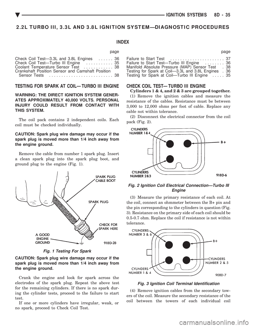
Remove the cable from number 1 spark plug. Insert
a clean spark plug into the spark plug boot, and
ground plug to the engine (Fig. 1).
CAUTION: Spark plug wire damage may occur if the
spark plug is moved more than 1/4 inch away from
the engine ground. Crank the engine and look for spark across the
electrodes of the spark plug. Repeat the above test
for the remaining cylinders. If there is no spark dur-
ing the cylinder tests, proceed to the failure to start
test. If one or more cylinders have irregular, weak, or
no spark, proceed to Check Coil Test.
CHECK COIL TESTÐTURBO III ENGINE
Cylinder s1&4,and2&3are grouped together.
(1) Remove the ignition cables and measure the
resistance of the cables. Resistance must be between
3,000 to 12,000 ohms per foot of cable. Replace any
cable not within tolerance. (2) Disconnect the electrical connector from the coil
pack (Fig. 2).
(3) Measure the primary resistance of each coil. At
the coil, connect an ohmmeter between the B+ pin and
the pin corresponding to the cylinders in question (Fig.
3). Resistance on the primary side of each coil should be
0.5-0.7 ohm. Replace the coil if resistance is not within
tolerance.
(4) Remove ignition cables from the secondary tow-
ers of the coil. Measure the secondary resistance of the
coil between the towers of each individual coil
Fig. 1 Testing For Spark
Fig. 2 Ignition Coil Electrical ConnectionÐTurbo III Engine
Fig. 3 Ignition Coil Terminal Identification
Ä IGNITION SYSTEMS 8D - 35
Page 480 of 2438
Refer to the appropriate Powertrain Diagnostics Pro-
cedure Manual. Refer to the wiring diagrams section
for circuit information.
COOLANT TEMPERATURE SENSOR TEST
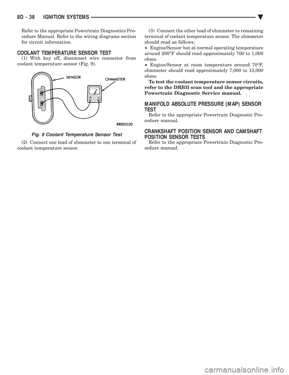
(1) With key off, disconnect wire connector from
coolant temperature sensor (Fig. 9).
(2) Connect one lead of ohmmeter to one terminal of
coolant temperature sensor. (3) Connect the other lead of ohmmeter to remaining
terminal of coolant temperature sensor. The ohmmeter
should read as follows;
² Engine/Sensor hot at normal operating temperature
around 200ÉF should read approximately 700 to 1,000
ohms.
² Engine/Sensor at room temperature around 70ÉF,
ohmmeter should read approximately 7,000 to 13,000
ohms. To test the coolant temperature sensor circuits,
refer to the DRBII scan tool and the appropriate
Powertrain Diagnostic Service manual.
MANIFOLD ABSOLUTE PRESSURE (MAP) SENSOR
TEST
Refer to the appropriate Powertrain Diagnostic Pro-
cedure manual.
CRANKSHAFT POSITION SENSOR AND CAMSHAFT
POSITION SENSOR TESTS
Refer to the appropriate Powertrain Diagnostic Pro-
cedure manual.
Fig. 9 Coolant Temperature Sensor Test
8D - 38 IGNITION SYSTEMS Ä
Page 481 of 2438
2.2L TURBO III, 3.3L AND 3.8L IGNITION SYSTEMSÐSERVICE PROCEDURES INDEX
page page
Camshaft Position Sensor ServiceÐTurbo III Engine.42Camshaft Position SensorÐ3.3L and 3.8L Engines.43
Coolant Temperature SensorÐ3.3L and 3.8L Engines .............................. 39
Coolant Temperature SensorÐTurbo III ........ 39
Crankshaft Position SensorÐ3.3L and 3.8L Engines.42
Crankshaft Position SensorÐTurbo III Engine . . . 42
Idle RPM Test ........................... 41
Ignition Coil ServiceÐTurbo III Engine ........ 43 Ignition CoilÐ3.3L and 3.8L Engine
........... 43
Knock SensorÐTurbo III Engines ............ 40
Manifold Absolute Pressure (MAP) SensorÐ3.3L and 3.8L Engines ....................... 44
Manifold Absolute Pressure (MAP) SensorÐ Turbo III Engine ........................ 44
Powertrain Control Module (PCM) ............ 39
Spark Plug Cable Service .................. 40
Spark Plug Service ....................... 41
POWERTRAIN CONTROL MODULE (PCM)
REMOVAL
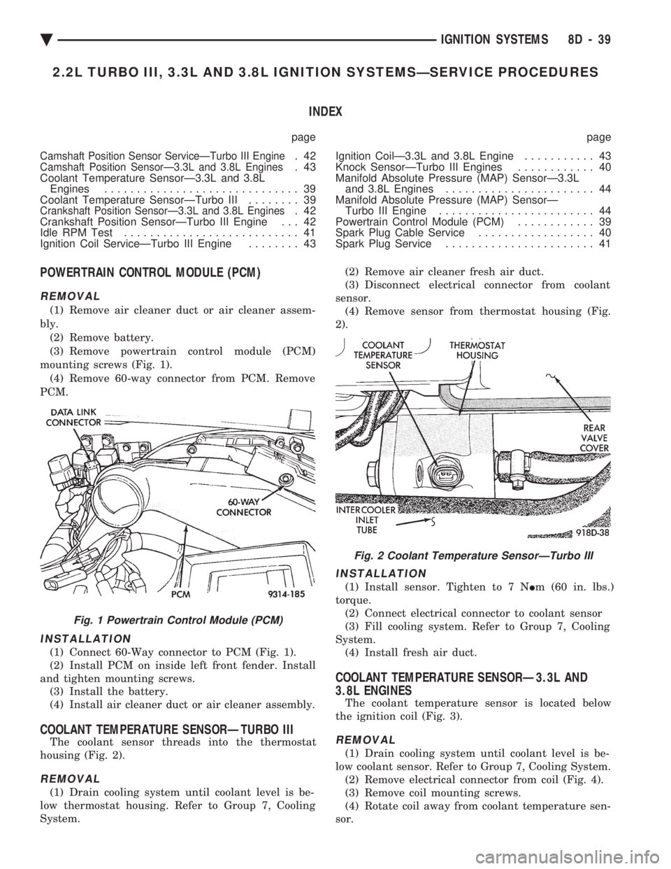
(1) Remove air cleaner duct or air cleaner assem-
bly. (2) Remove battery.
(3) Remove powertrain control module (PCM)
mounting screws (Fig. 1). (4) Remove 60-way connector from PCM. Remove
PCM.
INSTALLATION
(1) Connect 60-Way connector to PCM (Fig. 1).
(2) Install PCM on inside left front fender. Install
and tighten mounting screws. (3) Install the battery.
(4) Install air cleaner duct or air cleaner assembly.
COOLANT TEMPERATURE SENSORÐTURBO III
The coolant sensor threads into the thermostat
housing (Fig. 2).
REMOVAL
(1) Drain cooling system until coolant level is be-
low thermostat housing. Refer to Group 7, Cooling
System. (2) Remove air cleaner fresh air duct.
(3) Disconnect electrical connector from coolant
sensor. (4) Remove sensor from thermostat housing (Fig.
2).
INSTALLATION
(1) Install sensor. Tighten to 7 N Im (60 in. lbs.)
torque. (2) Connect electrical connector to coolant sensor
(3) Fill cooling system. Refer to Group 7, Cooling
System. (4) Install fresh air duct.
COOLANT TEMPERATURE SENSORÐ3.3L AND
3.8L ENGINES
The coolant temperature sensor is located below
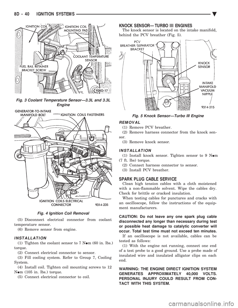
the ignition coil (Fig. 3).
REMOVAL
(1) Drain cooling system until coolant level is be-
low coolant sensor. Refer to Group 7, Cooling System. (2) Remove electrical connector from coil (Fig. 4).
(3) Remove coil mounting screws.
(4) Rotate coil away from coolant temperature sen-
sor.
Fig. 1 Powertrain Control Module (PCM)
Fig. 2 Coolant Temperature SensorÐTurbo III
Ä IGNITION SYSTEMS 8D - 39
Page 482 of 2438
(5) Disconnect electrical connector from coolant
temperature sensor. (6) Remove sensor from engine.
INSTALLATION
(1) Tighten the coolant sensor to 7 N Im (60 in. lbs.)
torque. (2) Connect electrical connector to sensor.
(3) Fill cooling system. Refer to Group 7, Cooling
System. (4) Install coil. Tighten coil mounting screws to 12
N Im (105 in. lbs.) torque.
(5) Connect electrical connector to coil.
KNOCK SENSORÐTURBO III ENGINES
The knock sensor is located on the intake manifold,
behind the PCV breather (Fig. 5).
REMOVAL
(1) Remove PCV breather.
(2) Remove harness connector from the knock sen-
sor. (3) Remove knock sensor.
INSTALLATION
(1) Install knock sensor. Tighten sensor to 9 N Im
(7 ft. lbs) torque. (2) Connect harness connector to sensor.
(3) Install PCV breather.
SPARK PLUG CABLE SERVICE
Clean high tension cables with a cloth moistened
with a non-flammable solvent. Wipe the cables dry.
Check for brittle or cracked insulation. When testing cables for punctures and cracks with
an oscilloscope, follow the instructions of the equip-
ment manufacturers.
CAUTION: Do not leave any one spark plug cable
disconnected any longer than necessary during test
or possible heat damage to catalytic converter will
occur. Total test time must not exceed ten minutes. If an oscilloscope is not available, cables can be
tested as follows: (1) With the engine not running, connect one end
of a test probe to a good ground. Use a probe made of
insulated wire and insulated alligator clips on each
end.
WARNING: THE ENGINE DIRECT IGNITION SYSTEM
GENERATES APPROXIMATELY 40,000 VOLTS.
PERSONAL INJURY COULD RESULT FROM CON-
TACT WITH THIS SYSTEM.
Fig. 3 Coolant Temperature SensorÐ3.3L and 3.3L Engine
Fig. 4 Ignition Coil Removal
Fig. 5 Knock SensorÐTurbo III Engine
8D - 40 IGNITION SYSTEMS Ä
Page 515 of 2438
AC AND AY BODIES INDEX
page page
Electronic Cluster ........................ 34
Gauges ................................ 28
General Information ....................... 23
Interior Lamp Replacement ................. 41 Mechanical Cluster and Gauge Service
........ 24
Mechanical/Electronic Cluster Removal ........ 25
Switch and Panel Component Service ......... 37
GENERAL INFORMATION
MECHANICAL CLUSTER
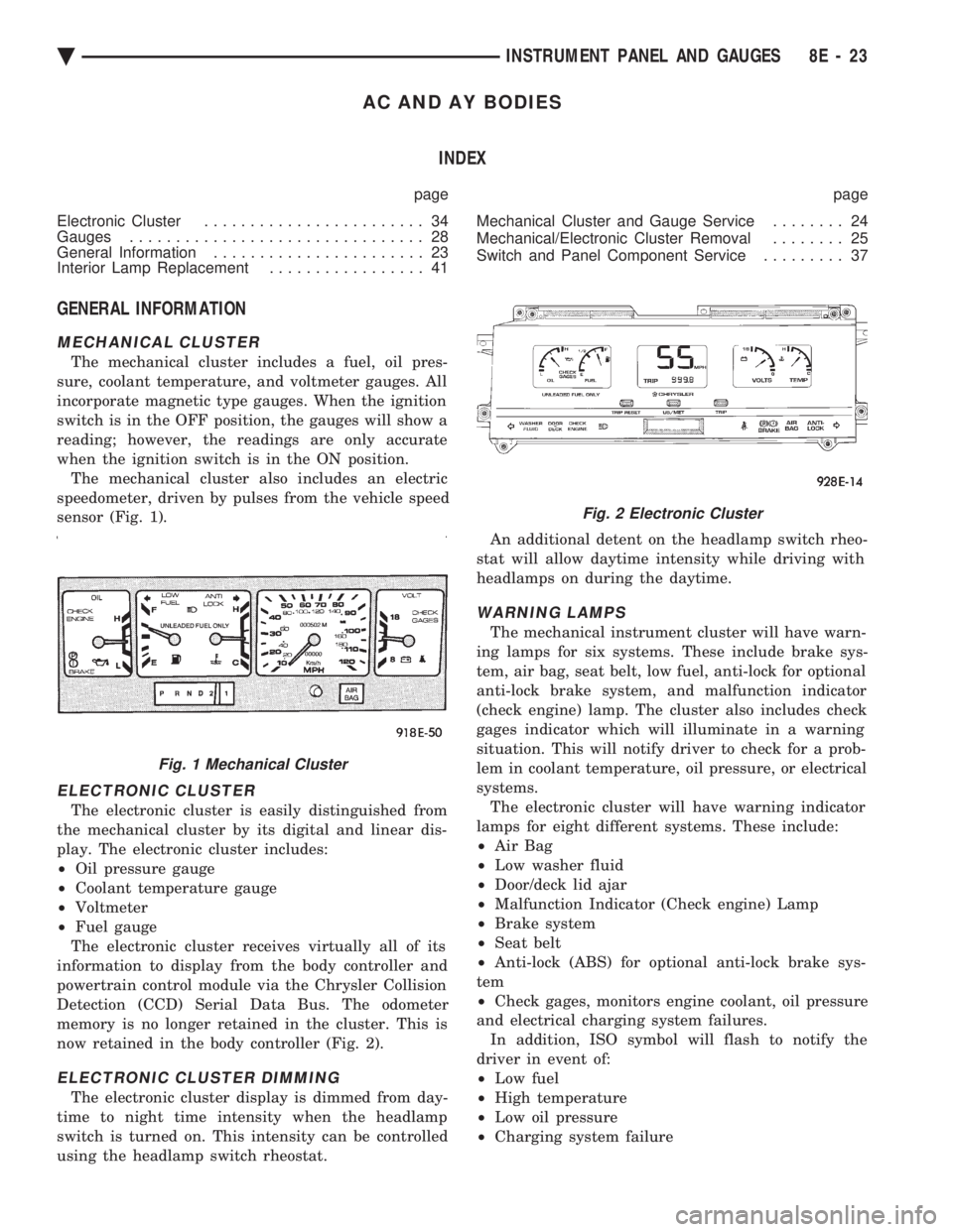
The mechanical cluster includes a fuel, oil pres-
sure, coolant temperature, and voltmeter gauges. All
incorporate magnetic type gauges. When the ignition
switch is in the OFF position, the gauges will show a
reading; however, the readings are only accurate
when the ignition switch is in the ON position. The mechanical cluster also includes an electric
speedometer, driven by pulses from the vehicle speed
sensor (Fig. 1).
ELECTRONIC CLUSTER
The electronic cluster is easily distinguished from
the mechanical cluster by its digital and linear dis-
play. The electronic cluster includes:
² Oil pressure gauge
² Coolant temperature gauge
² Voltmeter
² Fuel gauge
The electronic cluster receives virtually all of its
information to display from the body controller and
powertrain control module via the Chrysler Collision
Detection (CCD) Serial Data Bus. The odometer
memory is no longer retained in the cluster. This is
now retained in the body controller (Fig. 2).
ELECTRONIC CLUSTER DIMMING
The electronic cluster display is dimmed from day-
time to night time intensity when the headlamp
switch is turned on. This intensity can be controlled
using the headlamp switch rheostat. An additional detent on the headlamp switch rheo-
stat will allow daytime intensity while driving with
headlamps on during the daytime.
WARNING LAMPS
The mechanical instrument cluster will have warn-
ing lamps for six systems. These include brake sys-
tem, air bag, seat belt, low fuel, anti-lock for optional
anti-lock brake system, and malfunction indicator
(check engine) lamp. The cluster also includes check
gages indicator which will illuminate in a warning
situation. This will notify driver to check for a prob-
lem in coolant temperature, oil pressure, or electrical
systems. The electronic cluster will have warning indicator
lamps for eight different systems. These include:
² Air Bag
² Low washer fluid
² Door/deck lid ajar
² Malfunction Indicator (Check engine) Lamp
² Brake system
² Seat belt
² Anti-lock (ABS) for optional anti-lock brake sys-
tem
² Check gages, monitors engine coolant, oil pressure
and electrical charging system failures. In addition, ISO symbol will flash to notify the
driver in event of:
² Low fuel
² High temperature
² Low oil pressure
² Charging system failure
Fig. 1 Mechanical Cluster
Fig. 2 Electronic Cluster
Ä INSTRUMENT PANEL AND GAUGES 8E - 23
Page 547 of 2438
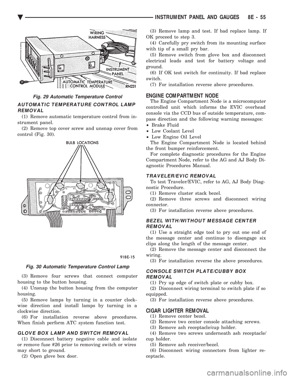
AUTOMATIC TEMPERATURE CONTROL LAMP REMOVAL
(1) Remove automatic temperature control from in-
strument panel. (2) Remove top cover screw and unsnap cover from
control (Fig. 30).
(3) Remove four screws that connect computer
housing to the button housing. (4) Unsnap the button housing from the computer
housing. (5) Remove lamps by turning in a counter clock-
wise direction and install lamps by turning in a
clockwise direction. (6) For installation reverse above procedures.
When finish perform ATC system function test.
GLOVE BOX LAMP AND SWITCH REMOVAL
(1) Disconnect battery negative cable and isolate
or remove fuse #26 prior to removing switch or wires
may short to ground. (2) Open glove box door. (3) Remove lamp and test. If bad replace lamp. If
OK proceed to step 3. (4) Carefully pry switch from its mounting surface
with tip of a small pry bar. (5) Remove switch from glove box and disconnect
electrical leads and test for battery voltage and
ground. (6) If OK test switch for continuity. If bad replace
switch. (7) For installation reverse above procedures.
ENGINE COMPARTMENT NODE
The Engine Compartment Node is a microcomputer
controlled unit which informs the EVIC overhead
console via the CCD bus of outside temperature, com-
pass direction and the following warning messages:
² Brake Fluid
² Low Coolant Level
² Low Engine Oil Level
The Engine Compartment Node is located behind
the front bumper reinforcement. For complete diagnostic procedures for the Engine
Compartment Node, refer to the AG and AJ Body Di-
agnostic Procedures Manual.
TRAVELER/EVIC REMOVAL
To test Traveler/EVIC, refer to AG, AJ Body Diag-
nostic Procedure. (1) Remove cluster stack bezel.
(2) Remove three screws and disconnect wiring
connector. (3) For installation reverse above procedures.
BEZEL WITH/WITHOUT MESSAGE CENTERREMOVAL
(1) Use a straight edge tool to pry out one end of
the message center and continue to disengage six
clips along the length of the message center. (2) Remove the message center and disconnect the
wiring. (3) For installation reverse the above procedures.
CONSOLE SWITCH PLATE/CUBBY BOXREMOVAL
(1) Pry up edge of switch plate or cubby box.
(2) Disconnect wiring terminal to switch plate if so
equipped. (3) For installation reverse above procedures.
CIGAR LIGHTER REMOVAL
(1) Remove center bezel.
(2) Remove two center console attaching screws.
(3) Remove ash receptacle/cup holder.
(4) Remove two screws underneath ash receptacle/
cup holder. (5) Remove ash receiver/bezel.
(6) Disconnect wiring connectors from lighter re-
ceptacle.
Fig. 29 Automatic Temperature Control
Fig. 30 Automatic Temperature Control Lamp
Ä INSTRUMENT PANEL AND GAUGES 8E - 55
Page 686 of 2438
AIR BAG MODULE
WARNING: BEFORE BEGINNING ANY AIR BAG
SYSTEM REMOVAL OR INSTALLATION PROCE-
DURES, REMOVE AND ISOLATE THE BATTERY
NEGATIVE (-) CABLE (GROUND) FROM THE VEHI-
CLE BATTERY. THIS IS THE ONLY SURE WAY TO
DISABLE THE AIR BAG SYSTEM. FAILURE TO DO
THIS COULD RESULT IN ACCIDENTAL AIR BAG
DEPLOYMENT AND POSSIBLE PERSONAL INJURY. UNDEPLOYED AIR BAG REMOVAL FROM THE
STEERING WHEEL: DISCONNECT BATTERY
GROUND CABLE AND ISOLATE. ALLOW SYS-
TEM CAPACITOR TO DISCHARGE FOR TWO
MINUTES. BEGIN AIR BAG REMOVAL.
REMOVAL
When removing a deployed module, wear rubber
gloves, eye protection and a long sleeve shirt as de-
posits may be on the surface which could irritate the
skin and eyes. (1) Disconnect battery negative cable and isolate.
(2) Wait two minutes for the reserve capacitor to
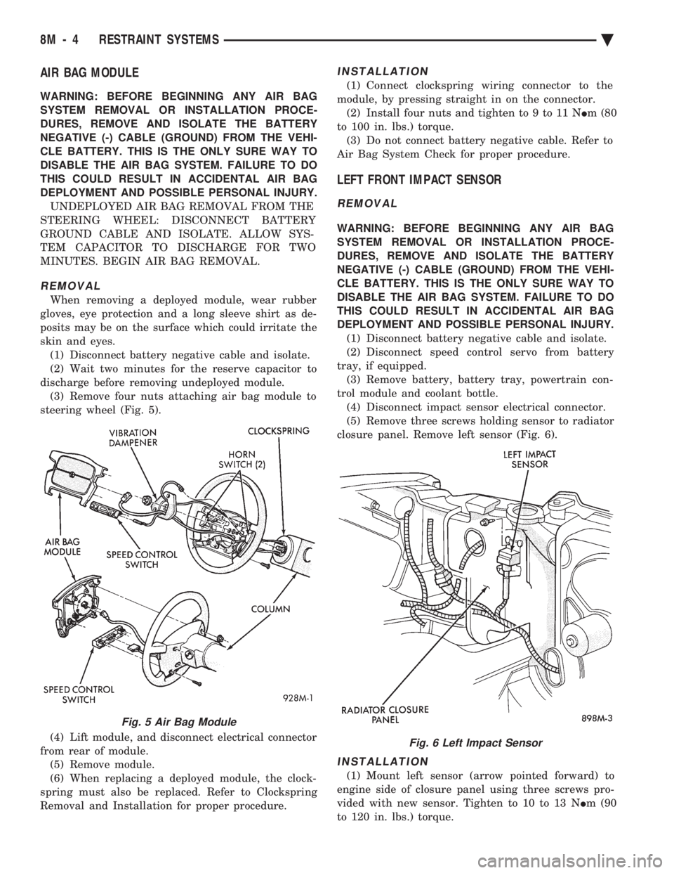
discharge before removing undeployed module. (3) Remove four nuts attaching air bag module to
steering wheel (Fig. 5).
(4) Lift module, and disconnect electrical connector
from rear of module. (5) Remove module.
(6) When replacing a deployed module, the clock-
spring must also be replaced. Refer to Clockspring
Removal and Installation for proper procedure.
INSTALLATION
(1) Connect clockspring wiring connector to the
module, by pressing straight in on the connector. (2) Install four nuts and tighten to 9 to 11 N Im (80
to 100 in. lbs.) torque. (3) Do not connect battery negative cable. Refer to
Air Bag System Check for proper procedure.
LEFT FRONT IMPACT SENSOR
REMOVAL
WARNING: BEFORE BEGINNING ANY AIR BAG
SYSTEM REMOVAL OR INSTALLATION PROCE-
DURES, REMOVE AND ISOLATE THE BATTERY
NEGATIVE (-) CABLE (GROUND) FROM THE VEHI-
CLE BATTERY. THIS IS THE ONLY SURE WAY TO
DISABLE THE AIR BAG SYSTEM. FAILURE TO DO
THIS COULD RESULT IN ACCIDENTAL AIR BAG
DEPLOYMENT AND POSSIBLE PERSONAL INJURY. (1) Disconnect battery negative cable and isolate.
(2) Disconnect speed control servo from battery
tray, if equipped. (3) Remove battery, battery tray, powertrain con-
trol module and coolant bottle. (4) Disconnect impact sensor electrical connector.
(5) Remove three screws holding sensor to radiator
closure panel. Remove left sensor (Fig. 6).
INSTALLATION
(1) Mount left sensor (arrow pointed forward) to
engine side of closure panel using three screws pro-
vided with new sensor. Tighten to 10 to 13 N Im (90
to 120 in. lbs.) torque.
Fig. 5 Air Bag Module
Fig. 6 Left Impact Sensor
8M - 4 RESTRAINT SYSTEMS Ä
Page 687 of 2438
(2) Connect sensor wiring lead from harness to
connector on body of sensor. (3) Install coolant bottle, powertrain control mod-
ule, battery tray and battery. (4) Install speed control servo to battery tray, if
equipped. (5) Do not connect negative battery cable. Refer to
Air Bag Systems Check for proper procedure.
RIGHT FRONT IMPACT SENSOR
REMOVAL
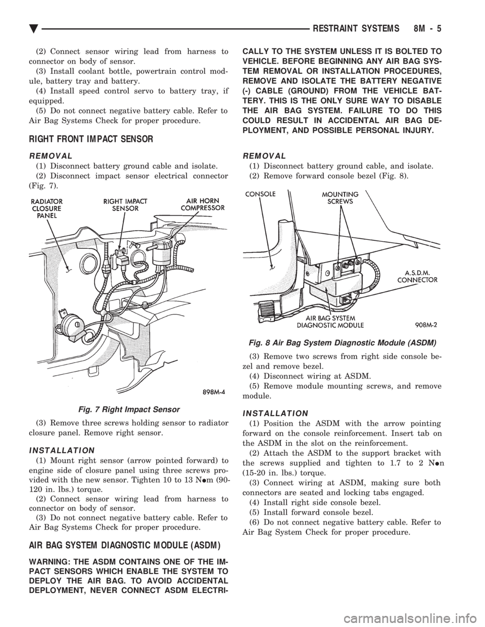
(1) Disconnect battery ground cable and isolate.
(2) Disconnect impact sensor electrical connector
(Fig. 7).
(3) Remove three screws holding sensor to radiator
closure panel. Remove right sensor.
INSTALLATION
(1) Mount right sensor (arrow pointed forward) to
engine side of closure panel using three screws pro-
vided with the new sensor. Tighten 10 to 13 N Im (90-
120 in. lbs.) torque. (2) Connect sensor wiring lead from harness to
connector on body of sensor. (3) Do not connect negative battery cable. Refer to
Air Bag Systems Check for proper procedure.
AIR BAG SYSTEM DIAGNOSTIC MODULE (ASDM)
WARNING: THE ASDM CONTAINS ONE OF THE IM-
PACT SENSORS WHICH ENABLE THE SYSTEM TO
DEPLOY THE AIR BAG. TO AVOID ACCIDENTAL
DEPLOYMENT, NEVER CONNECT ASDM ELECTRI- CALLY TO THE SYSTEM UNLESS IT IS BOLTED TO
VEHICLE. BEFORE BEGINNING ANY AIR BAG SYS-
TEM REMOVAL OR INSTALLATION PROCEDURES,
REMOVE AND ISOLATE THE BATTERY NEGATIVE
(-) CABLE (GROUND) FROM THE VEHICLE BAT-
TERY. THIS IS THE ONLY SURE WAY TO DISABLE
THE AIR BAG SYSTEM. FAILURE TO DO THIS
COULD RESULT IN ACCIDENTAL AIR BAG DE-
PLOYMENT, AND POSSIBLE PERSONAL INJURY.
REMOVAL
(1) Disconnect battery ground cable, and isolate.
(2) Remove forward console bezel (Fig. 8).
(3) Remove two screws from right side console be-
zel and remove bezel. (4) Disconnect wiring at ASDM.
(5) Remove module mounting screws, and remove
module.
INSTALLATION
(1) Position the ASDM with the arrow pointing
forward on the console reinforcement. Insert tab on
the ASDM in the slot on the reinforcement. (2) Attach the ASDM to the support bracket with
the screws supplied and tighten to 1.7 to 2 N In
(15-20 in. lbs.) torque. (3) Connect wiring at ASDM, making sure both
connectors are seated and locking tabs engaged. (4) Install right side console bezel.
(5) Install forward console bezel.
(6) Do not connect negative battery cable. Refer to
Air Bag System Check for proper procedure.
Fig. 7 Right Impact Sensor
Fig. 8 Air Bag System Diagnostic Module (ASDM)
Ä RESTRAINT SYSTEMS 8M - 5
Page 931 of 2438
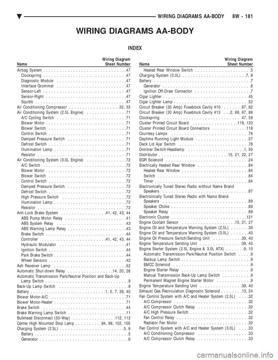
WIRING DIAGRAMS AA-BODY
INDEX
Wiring Diagram
Name Sheet Number
Airbag System ...............................47
Clockspring ...............................47
Diagnostic Module ..........................47
Interface Grommet ..........................47
Sensor-Left ...............................47
Sensor-Right ..............................47
Squibb ..................................47
Air Conditioning Compressor ...................32, 33
Air Conditioning System (2.5L Engine) ...............71
A/C Cycling Switch ..........................71
Blower Motor ..............................71
Blower Switch .............................71
Control Switch .............................71
Damped Pressure Switch ......................71
Defrost Switch .............................71
Illumination Lamp ...........................71
Resistor .................................71
Air Conditioning System (3.0L Engine) ...............72
A/C Switch ...............................72
Blower Motor ..............................72
Blower Switch .............................72
Control Switch .............................72
Damped Pressure Switch ......................72
Defrost Switch .............................72
High Pressure Switch ........................72
Illumination Lamp ...........................72
Resistor .................................72
Anti-Lock Brake System .................41, 42, 43, 44
ABS Pump Motor Relay .......................41
ABS System Relay ..........................43
ABS Warning Lamp Relay ......................43
Brake Switch ..............................44
Controller ....................... .41, 42, 43, 44
Hydraulic Modulator .........................41
Ignition Switch .............................44
Park Brake Switch ...........................44
Wheel Sensors .............................42
Ash Receiver Lamp ...........................52
Automatic Shut-down Relay .................14, 20, 28
Automatic Transmission Park/Neutral Position and Back-Up Lamp Switch ...............................9
Back-Up Lamp Switch ..........................9
Battery ............................1,5,7,39,40
Blower Motor-A/C ............................71
Blower Motor-Heater ...........................71
Brake Switch ...............................44
Brake Warning Lamp Switch ......................11
Bulkhead Disconnect (50-Way) ................112, 113
Center High Mounted Stop Lamp ..........94, 98, 102, 105
Charging System (2.5L) ........................5,6
Battery ...................................5
Generator .................................6Wiring Diagram
Name Sheet Number
Heated Rear Window Switch .....................5
Charging System (3.0L) ........................7,8
Battery ....................................7
Generator .................................8
Ignition Off-Draw Connector .....................7
Cigar Lighter ................................45
Cigar Lighter Lamp ............................52
Circuit Breaker (30 Amp) Fuseblock Cavity #10 .......67, 82
Circuit Breaker (30 Amp) Fuseblock Cavity #13 . . .2, 66, 67, 86
Clockspring ............................. .47, 59
Cluster Printed Circuit Board .................119, 120
Cluster Printed Circuit Board Connectors .............118
Courtesy Lamps .............................76
Daytime Running Light Module ....................57
Deck Lid Ajar Switch ..........................78
Dimmer Switch-Headlamp .....................1,50
Distributor ......................... .15, 21, 22, 27
EGR Solenoid ...............................24
Electrically Heated Rear Window ...................84
Heated Rear Window .........................84
Switch ..................................84
Timer ...................................84
Electronically Tuned Stereo Radio without Name Brand Speakers ................................87
Electronically Tuned Stereo Radio with Name Brand Speakers ................................89
Speaker Choke .............................89
Speaker Relay .............................89
Electronic Cluster ........................... .121
Engine Coolant Sensor ................... .15, 21, 27
Engine Oil and Temperature Warning System (2.5L) .......39
Engine Oil and Temperature Warning System (3.0L) .......40
Engine Oil Pressure Switch/Sending Unit ...........39, 40
Engine Temperature Sending Unit ................39, 40
Engine Starter System (2.5L Engine & 3.0L ATX) .......9,10
Automatic Transmission Park/Neutral Position Switch .....9
Backup Lamp Switch ..........................9
EMCC Solenoid .............................9
Engine Starter Relay ..........................9
Manual Transmission Back-Up Lamp Switch ...........9
Permanent Magnet Engine Starter Motor .............9
Engine Temperature Sending Unit ................39, 40
Exhaust Gas Recirculation Diagnostic Solenoid ........13, 24
Fan Control System with A/C and Heater System (2.5L) ....32
A/C Compressor ............................32
A/C Compressor Clutch Relay ...................32
A/C High Pressure Switch ......................32
Fan Control Relay ...........................32
Radiator Fan Motor ..........................32
Fan Control System with A/C and Heater System (3.0L) ....33
A/C Conditioning Compressor ...................33
A/C Compressor Clutch Relay ...................33
Ä WIRING DIAGRAMS AA-BODY 8W - 181
Page 932 of 2438
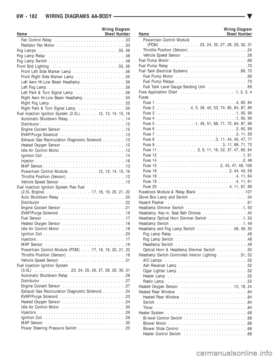
Wiring Diagram
Name Sheet Number
Fan Control Relay ...........................33
Radiator Fan Motor ..........................33
Fog Lamps ............................. .55, 56
Fog Lamp Relay .............................48
Fog Lamp Switch .............................48
Front End Lighting ........................ .55, 56
Front Left Side Marker Lamp ....................56
Front Right Side Marker Lamp ...................55
Left Aero Hi-Low Beam Headlamp .................56
Left Fog Lamp .............................56
Left Park & Turn Signal Lamp ...................56
Right Aero Hi-Low Beam Headlamp ................55
Right Fog Lamp ............................55
Right Park & Turn Signal Lamp ..................55
Fuel Injection Ignition System (2.5L) .......12, 13, 14, 15, 16
Automatic Shutdown Relay ......................14
Distributor ................................15
Engine Coolant Sensor ........................15
EVAP/Purge Solenoid .........................13
Exhaust Gas Recirculation Diagnostic Solenoid .........13
Heated Oxygen Sensor ........................12
Idle Air Control Motor .........................12
Ignition Coil ...............................14
Injector ..................................16
MAP Sensor ...............................13
Powertrain Control Module ............12, 13, 14, 15, 16
Throttle Position (Sensor) ......................12
Vehicle Speed Senosr .........................15
Fuel Injection Ignition System Flex Fuel (2.5L Engine) ................ .17, 18, 19, 20, 21, 22
Auto Shutdown Relay ........................20
Distributor ...............................22
Engine Coolant Sensor ........................21
EVAP/Purge Solenoid .........................19
Fuel Sensor ...............................17
Heated Oxygen Sensor ........................18
Idle Air Control Motor ........................18
Ignition Coil ...............................20
Injectors .................................17
MAP Sensor ..............................19
Powertrain Control Module (PCM) . . . .17, 18, 19, 20, 21, 22
Throttle Position (Sensor) ......................18
Vehicle Speed Sensor ........................21
Fuel Injection Ignition System (3.0L) ............. .23, 24, 25, 26, 27, 28, 29, 30, 31
Automatic Shutdown Relay .....................28
Distributor ...............................27
Engine Coolant Sensor ........................27
Exhaust Gas Recirculation Diagnostic Solenoid .........24
EVAP/Purge Solenoid .........................23
Heated Oxygen Sensor ........................24
Idle Air Control Motor ........................30
Injectors .................................26
Ignition Coil ...............................29
MAP Sensor ..............................30
Power Steering Pressure Switch ..................25Wiring Diagram
Name Sheet Number
Powertrain Control Module (PCM) .............. .23, 24, 25, 27, 28, 29, 30, 31
Throttle Position (Sensor) ......................24
Vehicle Speed Sensor ........................28
Fuel Pump Motor .............................69
Fuel Pump Relay .............................70
Fuel Tank Electrical Systems ...................69, 70
Fuel Pump Motor ...........................69
Fuel Pump Relays ...........................70
Fuel Tank Level Gauge Sending Unit ...............69
Fuse Application Chart .....................1,2,3,4
Fuses Fuse 1 ..............................4,80,84
Fuse 2 .............4,5,39,40,53,74,80,84,87,89
Fuse 3 ..............................1,95,99
Fuse 4 ..............................1,95,99
Fuse 5 ...............1,49,51,68,71,72,84,87,89
Fuse 6 ..............................2,65,89
Fuse 7 ..............................3,11,59
Fuse 8 ......................3,11,44,45,47,77
Fuse 9 .........................3,11,68,71,72
Fuse 11 ...............3,9,11,16,22,37,47,60,84
Fuse 12 ...............................1,61
Fuse 14 ...............................2,48
Fuse 15 .......................2,45,47,48,106
Fuse 16 ..........................2,44,45,59
Fuse 18 .............................4,11,64
Fuse 19 .............................4,11,61
Fuse 20 ..........................4,11,87,89
Fuseblock Module & Relay Blank ..................107
Glove Box Lamp and Switch ......................54
Hazard Flasher ..............................61
Headlamp Dimmer Switch .....................1,50
Headlamp, Key-in, Seat Belt Chimes .................45
Headlamp Optical Horn Dimmer Switch .............1,50
Headlamp Switch ...........................1,49
Headlamp and Fog Lamp Switch ..............48, 49, 50
Fog Lamp Relay ............................48
Fog Lamp Switch ...........................48
Headlamp Switch ...........................49
Optical Horn & Headlamp Dimmer Switch ............50
Headlamp Switch Controlled Interior Lighting .........51, 52
A/C Lamps ...............................52
Ash Receiver Lamp ..........................52
Cigar Lighter Lamp ..........................52
Heater Lamp ..............................52
Radio Lamp ...............................52
Heated Oxygen Sensor ................... .12, 18, 24
Heated Rear Window ..........................84
Heated Rear Window .........................84
Switch ..................................84
Timer ...................................84
Heater System ...............................68
Bi-level Control Switch ........................68
Blower Motor ..............................68
Blower Slide Control .........................68
Heater Control Switch ........................68
8W - 182 WIRING DIAGRAMS AA-BODY Ä