key battery CHEVROLET DYNASTY 1993 Repair Manual
[x] Cancel search | Manufacturer: CHEVROLET, Model Year: 1993, Model line: DYNASTY, Model: CHEVROLET DYNASTY 1993Pages: 2438, PDF Size: 74.98 MB
Page 2342 of 2438

FIXED DISPLACEMENT COMPRESSORÐMODEL SD709P INDEX
page page
Compressor ............................. 38
Compressor Clutch/Coil Assembly ............ 38
Compressor Shaft Seal .................... 41 Cylinder Head/Valve Plate
.................. 44
Description ............................. 38
Refrigerant System Diagnosis ............... 45
DESCRIPTION
The Sanden compressor is a 7 piston design. Sys-
tem lubrication is provided by 135 ml 615 ml (4.6 oz.
6 0.5 oz.) of 500 viscosity refrigerant oil.
The clutch used on the compressor consists of 3 ba-
sic components:
² The pulley
² Front plate
² Field coil
The pulley and field coil are attached to the front
head of the compressor with tapered snap rings. The
hub is keyed to the compressor shaft and is retained
on the shaft with a self-locking nut. Special service
tools are required to remove and install the clutch
plate on the compressor shaft.
COMPRESSOR
The A/C compressor may be removed and posi-
tioned without discharging the refrigerant system.
Discharging is not necessary if removing the A/C
compressor clutch/coil assembly, engine, cylinder
head, or generator.
WARNING: REFRIGERANT PRESSURES REMAIN
HIGH EVEN THOUGH THE ENGINE MAY BE
TURNED OFF. BEFORE REMOVING A FULLY
CHARGED COMPRESSOR, REVIEW THE SAFETY
PRECAUTIONS AND WARNINGS SECTION IN THIS
GROUP. DO NOT TWIST OR KINK THE REFRIGER-
ANT LINES WHEN REMOVING A FULLY CHARGED
COMPRESSOR. SAFETY GLASSES MUST BE
WORN.
REMOVAL
(1) Disconnect negative cable from battery.
(2) Loosen and remove drive belts (refer to group
7, Cooling System) and disconnect compressor clutch
wire lead. (3) Remove refrigerant lines from compressor (if
necessary). (4) Remove compressor attaching nuts and bolts.
(5) Remove compressor. If refrigerant lines were
not removed, lift compressor/clutch assembly and tie
it to a suitable component. To install, reverse the removal procedure.
COMPRESSOR CLUTCH/COIL ASSEMBLY
The magnetic clutch consists of a stationary elec-
tro-magnetic coil and a rotating pulley and plate as-
sembly. The electromagnetic coil is retained on the com-
pressor with a snap ring and is dimpled to maintain
its position. The pulley and plate assembly are mounted on the
compressor shaft. When the compressor is not in operation, the pul-
ley free wheels on the clutch hub bearing. When the
coil is energized the plate is magnetically engaged
with the pulley and turns the compressor shaft.
REMOVAL
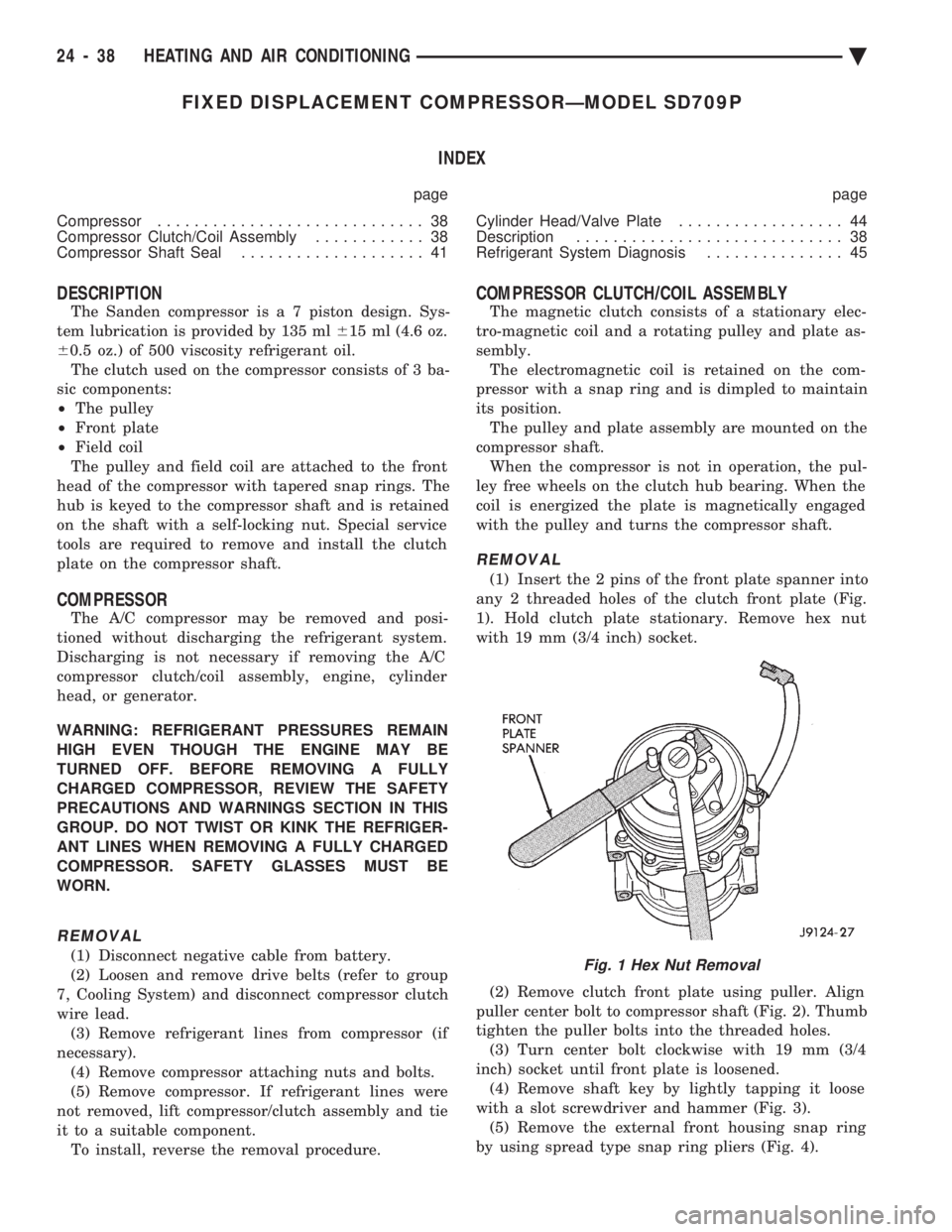
(1) Insert the 2 pins of the front plate spanner into
any 2 threaded holes of the clutch front plate (Fig.
1). Hold clutch plate stationary. Remove hex nut
with 19 mm (3/4 inch) socket.
(2) Remove clutch front plate using puller. Align
puller center bolt to compressor shaft (Fig. 2). Thumb
tighten the puller bolts into the threaded holes. (3) Turn center bolt clockwise with 19 mm (3/4
inch) socket until front plate is loosened. (4) Remove shaft key by lightly tapping it loose
with a slot screwdriver and hammer (Fig. 3). (5) Remove the external front housing snap ring
by using spread type snap ring pliers (Fig. 4).
Fig. 1 Hex Nut Removal
24 - 38 HEATING AND AIR CONDITIONING Ä
Page 2378 of 2438

Involves the wiring, blend-air door actuator, or the
ATC control head.
² DIAGNOSTIC TROUBLE CODES 3, 16, 17, 18, 19,
and 24 Involves the wiring, mode door actuator, or the ATC
control head.
² DIAGNOSTIC TROUBLE CODE 4
Involves the wiring, blend-air door actuator, mode
door actuator, fresh/recirc. door actuator, or the ATC
control head.
² DIAGNOSTIC TROUBLE CODE 5
Involves the wiring, fresh/recirc. door actuator, or the
ATC control head.
² DIAGNOSTIC TROUBLE CODE 6
Involves the compressor circuit signal wiring, or the
ATC control head.
² DIAGNOSTIC TROUBLE CODE 7
Involves the blower wiring, power module, or the
ATC control head.
² DIAGNOSTIC TROUBLE CODES 8, 21, 22
Requires replacing the ATC control head.
² DIAGNOSTIC TROUBLE CODES 9, and 27
Involves the wiring, sun sensor, or the ATC control
head.
² DIAGNOSTIC TROUBLE CODES 10, and 28
Involves the wiring, water temperature sensor, or the
ATC control head.
² DIAGNOSTIC TROUBLE CODES 11, and 25
Involves the wiring, ambient temperature sensor, or
the ATC control head.
² DIAGNOSTIC TROUBLE CODES 12, and 26
Involves the wiring, in-car temperature
sensor/aspirator, or the ATC control head.
DIAGNOSTIC TROUBLE CODE SERVICE PROCE-
DURES
The control keyboard will not function if pins
7, 9, 17, 19, or 20 of the 21-way wiring connector
are shorted to battery voltage. For electrical pin numbers, refer to the wiring Pin
out charts (Figs. 1, 2, 3, 4, 5, or 6).
DIAGNOSTIC TROUBLE CODE 1ÐOUTPUT FAILURE WITH ALL OUTPUTS LOW
(1) Remove pin #2 from 21-way connector on control
and retest system. If code 01 does not appear, the
control is good. Disconnect 21-way connector from control. With an
ohmmeter, measure the resistance between pin #2 and
pin #12 of 21-way. This should be between 2,600 and
2,800 ohms. If yes, the power module is good. Source of voltage on pin #2 is in the wiring. Repair
and retest system. (2) Remove pin #13 from 21-way connector on con-
trol and retest system. If code 01 does not appear, the
control is good. Locate source of voltage on pin #13.
Repair and retest system. (3) Remove pin #5 from 21-way connector on control
and retest system. If code 01 does not appear, the
control is good. Locate source of voltage on pin #5.
Repair and retest system. (4) Remove pin #6 from 21-way connector on control
and retest system. If code 01 does not appear, the
control is good. Locate source of voltage on pin #6.
Repair and retest system. (5) Remove pin #15 from 21-way connector on con-
trol and retest system. If code 01 does not appear, the
control is good. Locate source of voltage on pin #15.
Repair and retest system.
DIAGNOSTIC TROUBLE CODE 2ÐBLEND AC- TUATOR DRIVE SIGNAL NOT HIGH
If both Diagnostic Trouble Codes 2 and 3 occur
simultaneously, do both procedures. There is
typically only 1 failure. (1) Disconnect terminal #6 on the ATC control 21-
way connector and retest the system. Note that remov-
ing this terminal may generate additional Diagnostic
Trouble Codes. Disregard these at this time. (2) If Diagnostic Trouble Code 2 reappears, replace
control. (3) If code 2 does not reappear, the problem is a
shorted blend door actuator motor or a short to ground
in circuit 33 (pin #6). (4) Remove 21-way connector and check for continu-
ity from pin #6 to chassis ground. There should not be
any continuity. If continuity is there, repair wiring and
retest. (5) Check resistance across pins #6 and #4 of the
21-way for a shorted actuator motor. Resistance should
be between 20 and 50 ohms. If not correct, replace
actuator.
DIAGNOSTIC TROUBLE CODE 3ÐMODE AC- TUATOR DRIVE SIGNAL NOT HIGH
If both Diagnostic Trouble Codes 2 and 3 occur
simultaneously, do both procedures. There is
typically only 1 failure. (1) Disconnect terminal #5 on the ATC control 21-
way connector and retest the system. Removing this
terminal may generate additional Diagnostic Trouble
Codes. Disregard these at this time. (2) If Diagnostic Trouble Code 3 reappears, replace
control. (3) If code 3 does not reappear, the problem is a
shorted mode door actuator motor, or a short to ground
in circuit #35 (pin #5). (4) Remove 21-way and check for continuity from pin
#5 to chassis ground. There should not be any continu-
ity. If continuity is there, repair wiring and retest.
24 - 74 HEATING AND AIR CONDITIONING Ä