key battery CHEVROLET DYNASTY 1993 Workshop Manual
[x] Cancel search | Manufacturer: CHEVROLET, Model Year: 1993, Model line: DYNASTY, Model: CHEVROLET DYNASTY 1993Pages: 2438, PDF Size: 74.98 MB
Page 1874 of 2438
SYSTEM TESTS
WARNING: APPLY PARKING BRAKE AND/OR BLOCK
WHEELS BEFORE PERFORMING ANY TEST ON AN
OPERATING ENGINE.
OBTAINING DIAGNOSTIC TROUBLE CODES
(1) Connect DRBII scan tool to the data link connec-
tor located in the engine compartment near the pow-
ertrain control module (PCM). (2) Start the engine if possible, cycle the transaxle
selector and the A/Cswitch if applicable. Shut off the
engine. (3) Turn the ignition switch on, access Read Fault
Screen. Record all the fault messages shown on the
DRBII scan tool. Observe the malfunction indicator
lamp (Check Engine lamp on the instrument panel).
The lamp should light for 3 seconds then go out (bulb
check). Diagnostic trouble code erasure; access erase
diagnostic trouble code data
STATE DISPLAY TEST MODE
The switch inputs used by the powertrain control
module (PCM) have only two recognized states, HIGH
and LOW. For this reason, the PCM cannot recognize
the difference between a selected switch position ver-
sus an open circuit, a short circuit, or a defective
switch. If the change is displayed, it can be assumed
that the entire switch circuit to the PCM is functional.
From the state display screen access either State
Display Inputs and Outputs or State Display Sensors.
STATE DISPLAY INPUTS AND OUTPUTS
Connect the DRBII scan tool to the vehicle. Access
the State Display screen. Then access Inputs and
Outputs. The following is a list of the engine control
system functions accessible through the Inputs and
Outputs screen. Park/Neutral Switch
Speed Control Resume
Brake Switch
Speed Control On/Off
Speed Control Set
A/C Switch Sense
S/C Vent Solenoid
S/C Vacuum Solenoid
A/C Clutch Relay
EGR Solenoid
Auto Shutdown Relay
Radiator Fan Relay
Purge Solenoid
Torque Converter Clutch Solenoid
Malfunction Indicator Lamp (Check Engine Lamp)
STATE DISPLAY SENSORS
Connect the DRBII scan tool to the vehicle and ac-
cess the State Display screen. Then access Sensor
Display. The following is a list of the engine control
system functions accessible through the Sensor Dis-
play screen. Battery Temperature
Oxygen Sensor Signal
Engine Coolant Temperature
Engine Coolant Temp Sensor
Throttle Position
Minimum Throttle
Battery Voltage
MAP Sensor Reading
Idle Air Control Motor Position
Adaptive Fuel Factor
Barometric Pressure
Min Airflow Idle Speed
Engine Speed
Fault #1 Key-On Info
Module Spark Advance
Speed Control Target
Fault #2 Key-on Info
Fault #3 Key-on Info
Speed Control Status
Speed Control Switch Voltage
Charging System Goal
Theft Alarm Status
Map Sensor Voltage
Vehicle Speed
Oxygen Sensor State
MAP Gauge Reading
Throttle Opening (percentage)
Total Spark Advance
CIRCUIT ACTUATION TEST MODE
The circuit actuation test mode checks for proper
operation of output circuits or devices which the pow-
ertrain control module (PCM) cannot internally rec-
ognize. The PCM can attempt to activate these
outputs and allow an observer to verify proper oper-
ation. Most of the tests provide an audible or visual
indication of device operation (click of relay contacts,
spray fuel, etc.). Except for intermittent conditions, if
a device functions properly during testing, assume
the device, its associated wiring, and driver circuit
working correctly.
OBTAINING CIRCUIT ACTUATION TEST
Connect the DRBII scan tool to the vehicle and ac-
cess the Actuators screen. The following is a list of
the engine control system functions accessible
through Actuators screens. Stop All Tests
Ignition Coil #1
Fuel Injector #1
Fuel Injector #2
Fuel Injector #3
14 - 134 FUEL SYSTEMS Ä
Page 1881 of 2438
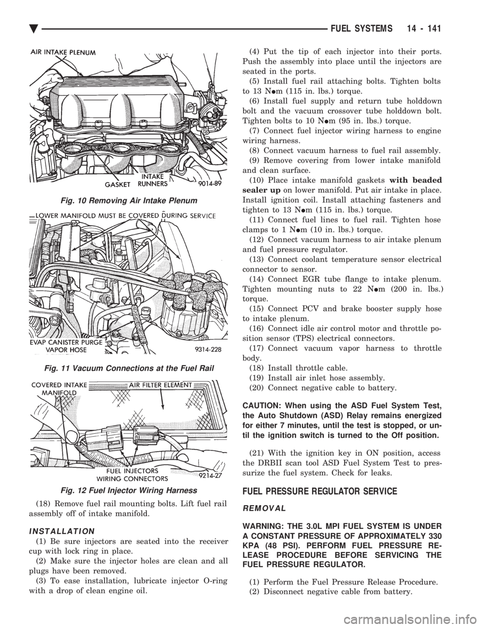
(18) Remove fuel rail mounting bolts. Lift fuel rail
assembly off of intake manifold.
INSTALLATION
(1) Be sure injectors are seated into the receiver
cup with lock ring in place. (2) Make sure the injector holes are clean and all
plugs have been removed. (3) To ease installation, lubricate injector O-ring
with a drop of clean engine oil. (4) Put the tip of each injector into their ports.
Push the assembly into place until the injectors are
seated in the ports. (5) Install fuel rail attaching bolts. Tighten bolts
to 13 N Im (115 in. lbs.) torque.
(6) Install fuel supply and return tube holddown
bolt and the vacuum crossover tube holddown bolt.
Tighten bolts to 10 N Im (95 in. lbs.) torque.
(7) Connect fuel injector wiring harness to engine
wiring harness. (8) Connect vacuum harness to fuel rail assembly.
(9) Remove covering from lower intake manifold
and clean surface. (10) Place intake manifold gaskets with beaded
sealer up on lower manifold. Put air intake in place.
Install ignition coil. Install attaching fasteners and
tighten to 13 N Im (115 in. lbs.) torque.
(11) Connect fuel lines to fuel rail. Tighten hose
clamps to 1 N Im (10 in. lbs.) torque.
(12) Connect vacuum harness to air intake plenum
and fuel pressure regulator. (13) Connect coolant temperature sensor electrical
connector to sensor. (14) Connect EGR tube flange to intake plenum.
Tighten mounting nuts to 22 N Im (200 in. lbs.)
torque. (15) Connect PCV and brake booster supply hose
to intake plenum. (16) Connect idle air control motor and throttle po-
sition sensor (TPS) electrical connectors. (17) Connect vacuum vapor harness to throttle
body. (18) Install throttle cable.
(19) Install air inlet hose assembly.
(20) Connect negative cable to battery.
CAUTION: When using the ASD Fuel System Test,
the Auto Shutdown (ASD) Relay remains energized
for either 7 minutes, until the test is stopped, or un-
til the ignition switch is turned to the Off position. (21) With the ignition key in ON position, access
the DRBII scan tool ASD Fuel System Test to pres-
surize the fuel system. Check for leaks.
FUEL PRESSURE REGULATOR SERVICE
REMOVAL
WARNING: THE 3.0L MPI FUEL SYSTEM IS UNDER
A CONSTANT PRESSURE OF APPROXIMATELY 330
KPA (48 PSI). PERFORM FUEL PRESSURE RE-
LEASE PROCEDURE BEFORE SERVICING THE
FUEL PRESSURE REGULATOR.
(1) Perform the Fuel Pressure Release Procedure.
(2) Disconnect negative cable from battery.
Fig. 10 Removing Air Intake Plenum
Fig. 11 Vacuum Connections at the Fuel Rail
Fig. 12 Fuel Injector Wiring Harness
Ä FUEL SYSTEMS 14 - 141
Page 1882 of 2438
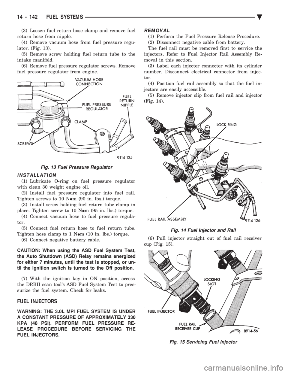
(3) Loosen fuel return hose clamp and remove fuel
return hose from nipple. (4) Remove vacuum hose from fuel pressure regu-
lator. (Fig. 13). (5) Remove screw holding fuel return tube to the
intake manifold. (6) Remove fuel pressure regulator screws. Remove
fuel pressure regulator from engine.
INSTALLATION
(1) Lubricate O-ring on fuel pressure regulator
with clean 30 weight engine oil. (2) Install fuel pressure regulator into fuel rail.
Tighten screws to 10 N Im (90 in. lbs.) torque.
(3) Install screw holding fuel return tube clamp in
place. Tighten screw to 10 N Im (95 in. lbs.) torque.
(4) Connect vacuum hose to fuel pressure regula-
tor. (5) Connect fuel return hose to fuel return tube.
Tighten hose clamp to 1 N Im (10 in. lbs.) torque.
(6) Connect negative battery cable.
CAUTION: When using the ASD Fuel System Test,
the Auto Shutdown (ASD) Relay remains energized
for either 7 minutes, until the test is stopped, or un-
til the ignition switch is turned to the Off position.
(7) With the ignition key in ON position, access
the DRBII scan tool's ASD Fuel System Test to pres-
surize the fuel system. Check for leaks.
FUEL INJECTORS
WARNING: THE 3.0L MPI FUEL SYSTEM IS UNDER
A CONSTANT PRESSURE OF APPROXIMATELY 330
KPA (48 PSI). PERFORM FUEL PRESSURE RE-
LEASE PROCEDURE BEFORE SERVICING THE
FUEL INJECTORS.
REMOVAL
(1) Perform the Fuel Pressure Release Procedure.
(2) Disconnect negative cable from battery.
The fuel rail must be removed first to service the
injectors. Refer to Fuel Injector Rail Assembly Re-
moval in this section. (3) Label each injector connector with its cylinder
number. Disconnect electrical connector from injec-
tor. (4) Position fuel rail assembly so that the fuel in-
jectors are easily accessible. (5) Remove injector clip from fuel rail and injector
(Fig. 14).
(6) Pull injector straight out of fuel rail receiver
cup (Fig. 15).
Fig. 13 Fuel Pressure Regulator
Fig. 14 Fuel Injector and Rail
Fig. 15 Servicing Fuel Injector
14 - 142 FUEL SYSTEMS Ä
Page 1883 of 2438
(7) Check injector O-ring for damage. If O-ring is
damaged, it must be replaced. If injector is to be re-
used, a protective cap must be installed on the injec-
tor tip to prevent damage. (8) Repeat procedure for remaining injectors.
INSTALLATION
(1) Before installing an injector, the rubber O-ring
must be lubricated with a drop of clean engine oil to
aid in installation. (2) Being careful not to damage O-ring, install in-
jector nozzle end into fuel rail receiver cap (Fig. 15). (3) Install injector clip by sliding open end into top
slot of the injector. The edge of the receiver cup will
slide into the side slots of clip (Fig. 14). (4) Repeat steps for remaining injectors.
(5) Install fuel rail assembly. Refer to Fuel Rail
Assembly Installation in this section. (6) Connect electrical connectors to injectors in cor-
rect order. (7) Connect negative battery cable.
CAUTION: When using the ASD Fuel System Test,
the Auto Shutdown (ASD) Relay remains energized
for either 7 minutes, until the test is stopped, or un-
til the ignition switch is turned to the Off position.
(8) With the ignition key in ON position, access
the DRBII scan tool ASD Fuel System Test to pres-
surize the fuel system. Check for leaks.
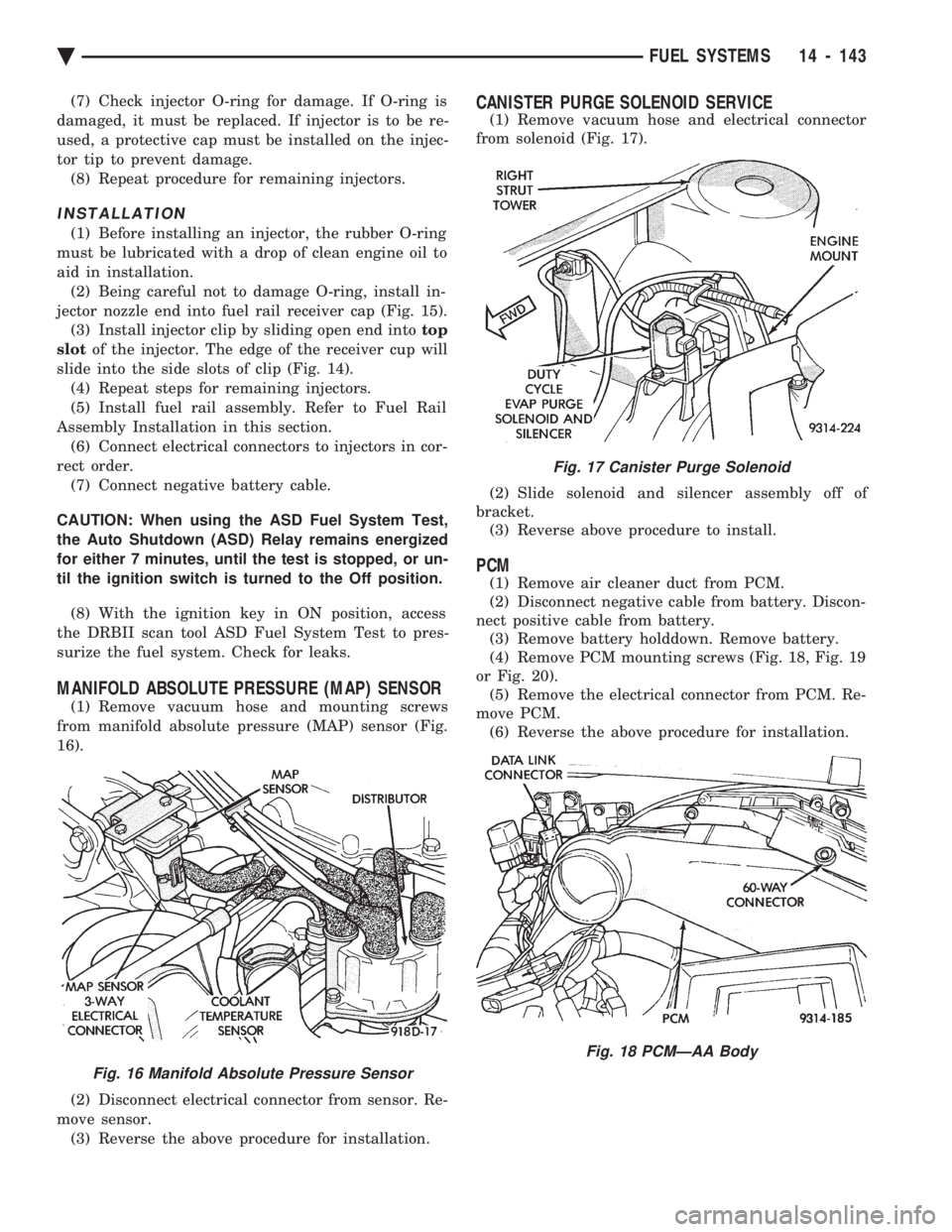
MANIFOLD ABSOLUTE PRESSURE (MAP) SENSOR
(1) Remove vacuum hose and mounting screws
from manifold absolute pressure (MAP) sensor (Fig.
16).
(2) Disconnect electrical connector from sensor. Re-
move sensor. (3) Reverse the above procedure for installation.
CANISTER PURGE SOLENOID SERVICE
(1) Remove vacuum hose and electrical connector
from solenoid (Fig. 17).
(2) Slide solenoid and silencer assembly off of
bracket. (3) Reverse above procedure to install.
PCM
(1) Remove air cleaner duct from PCM.
(2) Disconnect negative cable from battery. Discon-
nect positive cable from battery. (3) Remove battery holddown. Remove battery.
(4) Remove PCM mounting screws (Fig. 18, Fig. 19
or Fig. 20). (5) Remove the electrical connector from PCM. Re-
move PCM. (6) Reverse the above procedure for installation.
Fig. 16 Manifold Absolute Pressure Sensor
Fig. 17 Canister Purge Solenoid
Fig. 18 PCMÐAA Body
Ä FUEL SYSTEMS 14 - 143
Page 1891 of 2438
within a range of 12.9 to 15.0 volts. Refer to Group
8A for charging system information.
AUTO SHUTDOWN (ASD) RELAY AND FUEL PUMP
RELAYÐPCM OUTPUT
The PCM operates the auto shutdown (ASD) relay
and fuel pump relay through one ground path. The
PCM operates the relays by switching the ground
path on and off. Both relays turn on and off at the
same time. The ASD relay connects battery voltage to the fuel
injector and ignition coil. The fuel pump relay con-
nects battery voltage to the fuel pump and oxygen
sensor heating element. The PCM turns the ground path off when the igni-
tion switch is in the Off position. Both relays are off.
When the ignition switch is in the On or Crank po-
sition, the PCM monitors the crankshaft position
sensor and camshaft position sensor signals to deter-
mine engine speed and ignition timing (coil dwell). If
the PCM does not receive the crankshaft position
sensor and camshaft position sensor signals when the
ignition switch is in the Run position, it de-energizes
both relays. When the relays are de-energized, bat-
tery voltage is not supplied to the fuel injector, igni-
tion coil, fuel pump and oxygen sensor heating
element. The ASD relay and fuel pump relay are located in
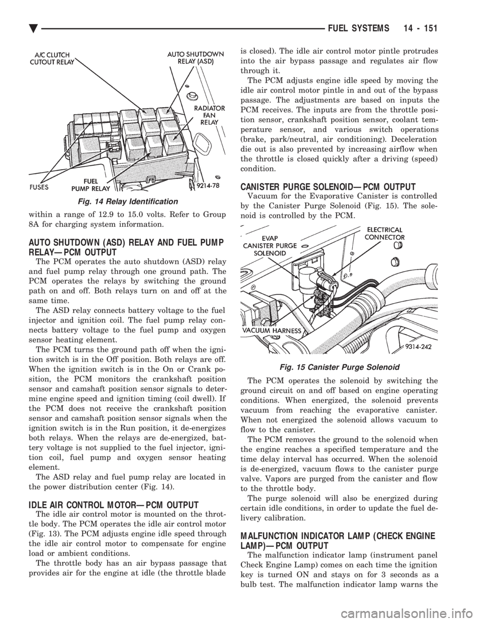
the power distribution center (Fig. 14).
IDLE AIR CONTROL MOTORÐPCM OUTPUT
The idle air control motor is mounted on the throt-
tle body. The PCM operates the idle air control motor
(Fig. 13). The PCM adjusts engine idle speed through
the idle air control motor to compensate for engine
load or ambient conditions. The throttle body has an air bypass passage that
provides air for the engine at idle (the throttle blade is closed). The idle air control motor pintle protrudes
into the air bypass passage and regulates air flow
through it. The PCM adjusts engine idle speed by moving the
idle air control motor pintle in and out of the bypass
passage. The adjustments are based on inputs the
PCM receives. The inputs are from the throttle posi-
tion sensor, crankshaft position sensor, coolant tem-
perature sensor, and various switch operations
(brake, park/neutral, air conditioning). Deceleration
die out is also prevented by increasing airflow when
the throttle is closed quickly after a driving (speed)
condition.
CANISTER PURGE SOLENOIDÐPCM OUTPUT
Vacuum for the Evaporative Canister is controlled
by the Canister Purge Solenoid (Fig. 15). The sole-
noid is controlled by the PCM.
The PCM operates the solenoid by switching the
ground circuit on and off based on engine operating
conditions. When energized, the solenoid prevents
vacuum from reaching the evaporative canister.
When not energized the solenoid allows vacuum to
flow to the canister. The PCM removes the ground to the solenoid when
the engine reaches a specified temperature and the
time delay interval has occurred. When the solenoid
is de-energized, vacuum flows to the canister purge
valve. Vapors are purged from the canister and flow
to the throttle body. The purge solenoid will also be energized during
certain idle conditions, in order to update the fuel de-
livery calibration.
MALFUNCTION INDICATOR LAMP (CHECK ENGINE
LAMP)ÐPCM OUTPUT
The malfunction indicator lamp (instrument panel
Check Engine Lamp) comes on each time the ignition
key is turned ON and stays on for 3 seconds as a
bulb test. The malfunction indicator lamp warns the
Fig. 14 Relay Identification
Fig. 15 Canister Purge Solenoid
Ä FUEL SYSTEMS 14 - 151
Page 1894 of 2438
IGNITION SWITCH ON (ZERO RPM) MODE When the multi-port fuel injection system is acti-
vated by the ignition switch, the following actions oc-
cur:
² The PCM determines atmospheric air pressure
from the MAP sensor input to determine basic fuel
strategy.
² The PCM monitors the coolant temperature sensor
and throttle position sensor input. The PCM modifies
fuel strategy based on this input. When the key is in the ON position and the engine
is not running (zero rpm), the auto shutdown (ASD)
relay and fuel pump relay are not energized. There-
fore battery voltage is not supplied to the fuel pump,
ignition coil, fuel injectors or oxygen sensor heating
element.
ENGINE START-UP MODE
This is an OPEN LOOP mode. The following ac-
tions occur when the starter motor is engaged. If the PCM receives the camshaft position sensor
and crankshaft position sensor signals, it energizes
the auto shutdown (ASD) relay and fuel pump relay.
These relays supply battery voltage to the fuel pump,
fuel injectors, ignition coil, and oxygen sensor heat-
ing element. If the PCM does not receive the cam-
shaft position sensor and crankshaft position sensor
signals within approximately one second, it de-ener-
gizes the ASD relay and fuel pump relay. The PCM energizes all six injectors until it deter-
mines crankshaft position from the camshaft position
sensor and crankshaft position sensor signals. The
PCM determines crankshaft position within 1 engine
revolution. After determining crankshaft position, the PCM
begins energizing the injectors in sequence. The PCM
adjusts injector pulse width and controls injector syn-
chronization by turning the individual ground paths
to the injectors On and Off. When the engine idles within 664 RPM of its tar-
get RPM, the PCM compares current MAP sensor
value with the atmospheric pressure value received
during the Ignition Switch On (Zero RPM) mode. If
the PCM does not detect a minimum difference be-
tween the two values, it sets a MAP fault into mem-
ory. Once the ASD and fuel pump relays have been en-
ergized, the PCM:
² Determines injector pulse width based on battery
voltage, coolant temperature, engine rpm and the
number of engine revolutions since cranking was ini-
tiated.
ENGINE WARM-UP MODE This is a OPEN LOOP mode. The following inputs
are received by the PCM:
² engine coolant temperature ²
manifold absolute pressure (MAP)
² engine speed (crankshaft position sensor)
² throttle position
² A/C switch
² battery voltage
The PCM adjusts injector pulse width and controls
injector synchronization by turning the individual
ground paths to the injectors On and Off. The PCM adjusts ignition timing and engine idle
speed. Engine idle speed is adjusted through the idle
air control motor.
CRUISE OR IDLE MODE
When the engine is at operating temperature this
is a CLOSED LOOP mode. During cruising speed the
following inputs are received by the PCM:
² engine coolant temperature
² manifold absolute pressure
² engine speed (crankshaft position sensor)
² throttle position
² exhaust gas oxygen content
² A/C control positions
² battery voltage
The PCM adjusts injector pulse width and controls
injector synchronization by turning the individual
ground paths to the injectors On and Off. The PCM adjusts engine idle speed and ignition
timing. The PCM adjusts the air/fuel ratio according
to the oxygen content in the exhaust gas.
ACCELERATION MODE This is a CLOSED LOOP mode. The PCM recog-
nizes an abrupt increase in throttle position or MAP
pressure as a demand for increased engine output
and vehicle acceleration. The PCM increases injector
pulse width in response to increased fuel demand.
DECELERATION MODE This is a CLOSED LOOP mode. During decelera-
tion the following inputs are received by the PCM:
² engine coolant temperature
² manifold absolute pressure
² engine speed
² throttle position
² exhaust gas oxygen content
² A/C control positions
² battery voltage
The PCM may receive a closed throttle input from
the throttle position sensor (TPS) when it senses an
abrupt decrease in manifold pressure. This indicates
a hard deceleration. The PCM will reduce injector
pulse width. This helps maintain better control of the
air-fuel mixture (as sensed through the O
2sensor).
During a closed throttle deceleration condition, the
PCM grounds the exhaust gas recirculation (EGR)
solenoid. When the solenoid is grounded, EGR func-
tion stops.
14 - 154 FUEL SYSTEMS Ä
Page 1906 of 2438
S/C Vacuum Solenoid
A/C Clutch Relay
EGR Solenoid
Auto Shutdown Relay
Radiator Fan Relay
Purge Solenoid
Malfunction Indicator Lamp (Check Engine Lamp)
STATE DISPLAY SENSORS
Connect the DRBII scan tool to the vehicle and ac-
cess the State Display screen. Then access Sensor
Display. The following is a list of the engine control
system functions accessible through the Sensor Dis-
play screen. Oxygen Sensor Signal
Engine Coolant Temperature
Engine Coolant Temp Sensor
Throttle Position
Minimum Throttle
Battery Voltage
MAP Sensor Reading
Idle Air Control Motor Position
Adaptive Fuel Factor
Barometric Pressure
Min Airflow Idle Spd (speed)
Engine Speed
DIS Sensor Status
Fault #1 Key-On Info
Module Spark Advance
Speed Control Target
Fault #2 Key-on Info
Fault #3 Key-on Info
Speed Control Status
Speed Control Switch Voltage
Charging System Goal
Theft Alarm Status
Map Sensor Voltage
Vehicle Speed
Oxygen Sensor State
MAP Gauge Reading
Throttle Opening (percentage)
Total Spark Advance
CIRCUIT ACTUATION TEST MODE
The circuit actuation test mode checks for proper
operation of output circuits or devices which the pow-
ertrain control module (PCM) cannot internally rec-
ognize. The PCM can attempt to activate these
outputs and allow an observer to verify proper oper-
ation. Most of the tests provide an audible or visual
indication of device operation (click of relay contacts,
spray fuel, etc.). Except for intermittent conditions, if
a device functions properly during testing, assume
the device, its associated wiring, and driver circuit
working correctly.
OBTAINING CIRCUIT ACTUATION TEST
Connect the DRBII scan tool to the vehicle and ac-
cess the Actuators screen. The following is a list of
the engine control system functions accessible
through Actuators screens. Stop All Tests
Ignition Coil #1
Ignition Coil #2
Ignition Coil #3
Fuel Injector #1
Fuel Injector #2
Fuel Injector #3
Fuel Injector #4
Fuel Injector #5
Fuel Injector #6
Idle Air Control Motor Open/Close
Radiator Fan Relay
A/C Clutch Relay
Auto Shutdown Relay
EVAP Purge Solenoid
S/C Servo Solenoids
Generator Field
EGR Solenoid
All Solenoids/Relays
ASD Fuel System Test
Speed Control Vacuum Solenoid
Speed Control Vent Solenoid
THROTTLE BODY MINIMUM AIR FLOW CHECK
PROCEDURE
(1) Warm engine in Park or Neutral until the cool-
ing fan has cycled on and off at least once. (2) Ensure that all accessories are off.
(3) Shut off engine.
(4) Disconnect the PCV valve hose from the intake
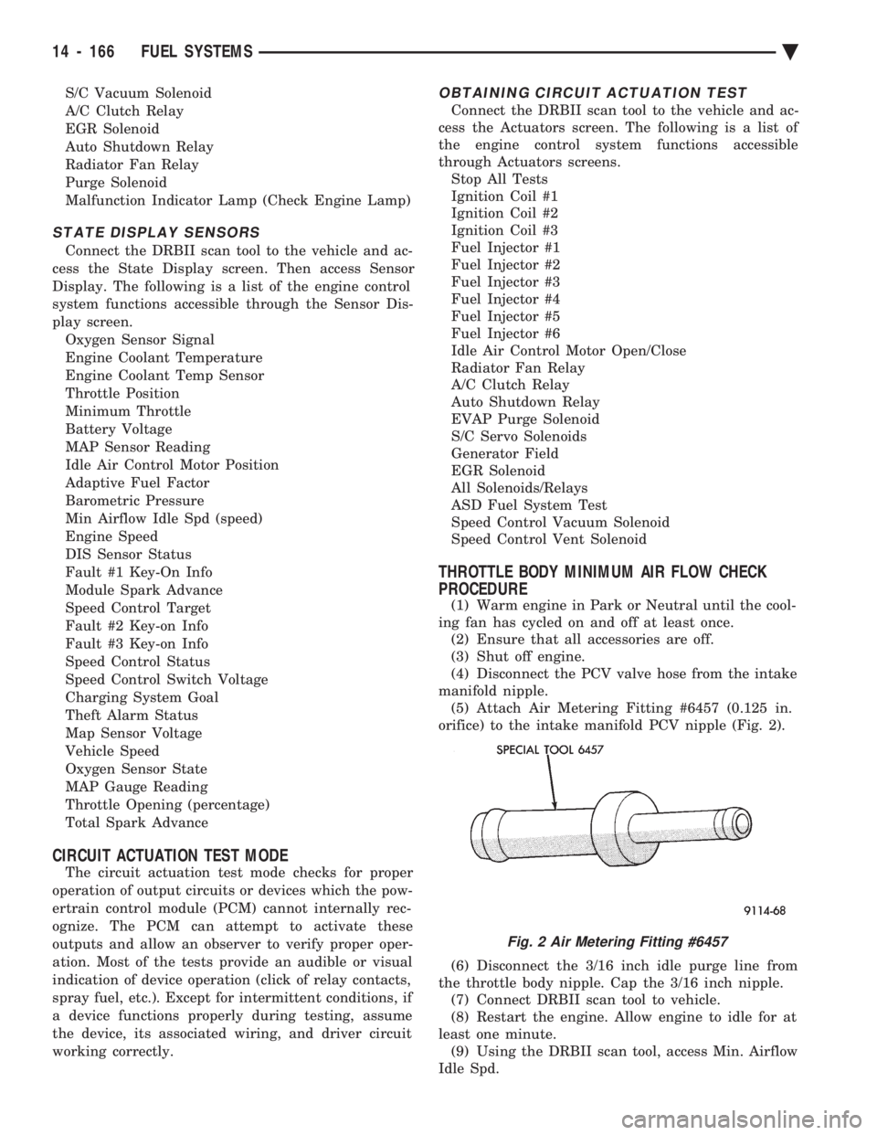
manifold nipple. (5) Attach Air Metering Fitting #6457 (0.125 in.
orifice) to the intake manifold PCV nipple (Fig. 2).
(6) Disconnect the 3/16 inch idle purge line from
the throttle body nipple. Cap the 3/16 inch nipple. (7) Connect DRBII scan tool to vehicle.
(8) Restart the engine. Allow engine to idle for at
least one minute. (9) Using the DRBII scan tool, access Min. Airflow
Idle Spd.
Fig. 2 Air Metering Fitting #6457
14 - 166 FUEL SYSTEMS Ä
Page 1913 of 2438
(5) Install fuel tube retaining bracket screw.
Tighten screw to 4 N Im (35 in. lbs.) torque.
(6) Connect electrical connectors to camshaft posi-
tion sensor, coolant temperature sensor and engine
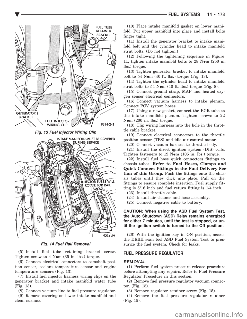
temperature sensors (Fig. 13). (7) Install fuel injector harness wiring clips on the
generator bracket and intake manifold water tube
(Fig. 13). (8) Connect vacuum line to fuel pressure regulator.
(9) Remove covering on lower intake manifold and
clean surface. (10) Place intake manifold gasket on lower mani-
fold. Put upper manifold into place and install bolts
finger tight. (11) Install the generator bracket to intake mani-
fold bolt and the cylinder head to intake manifold
strut bolts. (Do not tighten.) (12) Following the tightening sequence in Figure
11, tighten intake manifold bolts to 28 N Im (250 in.
lbs.) torque. (13) Tighten generator bracket to intake manifold
bolt to 54 N Im (40 ft. lbs.) torque (Fig. 13).
(14) Tighten the cylinder head to intake manifold
strut bolts to 54 N Im (40 ft. lbs.) torque (Fig. 8).
(15) Connect ground strap, MAP and heated oxy-
gen sensor electrical connectors. (16) Connect vacuum harness to intake plenum.
Connect PCV system hoses. (17) Using a new gasket, connect the EGR tube to
the intake manifold plenum. Tighten screws to 22
N Im (200 in. lbs.) torque.
(18) Clip wiring harness into the hole in the throt-
tle cable bracket. (19) Connect electrical connectors to the throttle
position sensor (TPS) and idle air control motor. (20) Connect vacuum harness to throttle body.
(21) Install the direct ignition system (DIS) coils.
Tighten fasteners to 12 N Im (105 in. lbs.) torque.
(22) Install fuel hose quick connectors fittings to
chassis tubes. Refer to Fuel Hoses, Clamps and
Quick Connect Fittings in the Fuel Delivery Sec-
tion of this Group. Push the fittings onto the chas-
sis tubes until they click into place. Pull on the
fittings to ensure complete insertion. Fuel supply fit-
ting is 5/16 inch and fuel return fitting is 1/4 inch. (23) Install throttle cable.
(24) Install air cleaner and hose assembly.
(25) Connect negative cable to battery.
CAUTION: When using the ASD Fuel System Test,
the Auto Shutdown (ASD) Relay remains energized
for either 7 minutes, until the test is stopped, or un-
til the ignition switch is turned to the Off position.
(26) With the ignition key in ON position, access
the DRBII scan tool ASD Fuel System Test to pres-
surize the fuel system. Check for leaks.FUEL PRESSURE REGULATOR
REMOVAL
(1) Perform fuel system pressure release procedure
before attempting any repairs. Refer to Fuel Pressure
Regulator Procedure in this section. (2) Remove fuel pressure regulator vacuum connec-
tor. (Fig. 15). (3) Remove regulator retainer screw (Fig. 15).
(4) Remove the fuel pressure regulator retainer
(Fig. 15).
Fig. 13 Fuel Injector Wiring Clip
Fig. 14 Fuel Rail Removal
Ä FUEL SYSTEMS 14 - 173
Page 1952 of 2438
(16) Connect the battery ground (negative) cable.
Test the operation of the lights and horns. If applica-
ble, reset the clock and radio.
STEERING COLUMN COMPONENT SERVICE
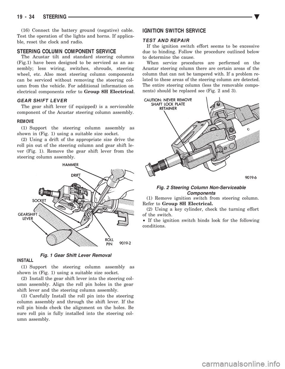
The Acustar tilt and standard steering columns
(Fig.1) have been designed to be serviced as an as-
sembly; less wiring, switches, shrouds, steering
wheel, etc. Also most steering column components
can be serviced without removing the steering col-
umn from the vehicle. For additional information on
electrical components refer to Group 8H Electrical.
GEAR SHIFT LEVER
The gear shift lever (if equipped) is a serviceable
component of the Acustar steering column assembly.
REMOVE (1) Support the steering column assembly as
shown in (Fig. 1) using a suitable size socket. (2) Using a drift of the appropriate size drive the
roll pin out of the steering column and gear shift le-
ver (Fig. 1). Remove the gear shift lever from the
steering column assembly.
INSTALL (1) Support the steering column assembly as
shown in (Fig. 1) using a suitable size socket. (2) Install the gear shift lever into the steering col-
umn assembly. Align the roll pin holes in the gear
shift lever and the steering column assembly. (3) Carefully Install the roll pin into the steering
column assembly and through the shift lever. If the
roll pin binds check the alignment on the holes. Be
sure roll pin is fully installed into the steering col-
umn assembly.
IGNITION SWITCH SERVICE
TEST AND REPAIR
If the ignition switch effort seems to be excessive
due to binding. Follow the procedure outlined below
to determine the cause.
When service procedures are performed on the
Acustar steering column there are certain areas of the
column that can not be tampered with. If a problem re-
lated to these areas of the steering column are detected.
The entire steering column (less the removable compo-
nents) should be replaced see (Fig. 2 and 3).
(1) Remove ignition switch from steering column.
Refer to Group 8H Electrical.
(2) Using a key cylinder, check the turning effort
of the switch.
² If the ignition switch binds look for the following
conditions.
Fig. 1 Gear Shift Lever Removal
Fig. 2 Steering Column Non-Serviceable Components
19 - 34 STEERING Ä
Page 2105 of 2438
41TE ON-BOARD DIAGNOSTICS INDEX
page page
CCD Bus .............................. 145
Diagnostic Trouble Code Charts ............ 146
Diagnostic Trouble Codes ................. 145
DRB II Scan Tool ....................... 146 General Information
...................... 145
Limp-In Mode .......................... 145
On-Board Diagnostics Information ........... 145
GENERAL INFORMATION
The information in this manual is designed to help
the technician understand and repair the transaxle
with the aid of the built in on-board diagnostics. Chrysler Corporation has developed a com-
plete set of diagnostic manuals which cover the
diagnosis of the 41TE transaxle. They have been
designed to make transaxle diagnosis accurate
and simple. Use these manuals with the DRB II
scan tool and the latest cartridge, when diagnos-
ing transaxle problems.
ON-BOARD DIAGNOSTICS INFORMATION
The 41TE transaxle is controlled and monitored by
the transmission control module. The transmission
control module monitors critical input and output
circuits within the transaxle. Some circuits are tested continuously; others are
checked only under certain conditions. Each circuit
monitored by the transmission control module has a
corresponding fault message assigned to it that can be
read with the DRB II scan tool. If the on-board diagnostic system senses that one of
the circuits is malfunctioning, the corresponding code
is stored in memory. If the malfunction goes away after
the code is stored, the transmission control module will
erase the code after 75 key cycles.
CCD BUS
In order to diagnose the 41TE transaxle, diagnostic
trouble codes in the transmission control module's
memory should be read. Use the Diagnostic Readout
Box (DRB II) scan tool to read codes. If more than one
diagnostic trouble code exists, diagnostic priority
should be given to the most recent code. With CCD bus
bias and communication problems, the DRB II scan
tool displays an appropriate message. Diagnostic
trouble codes might not be accessible until the bus
problem is fixed. The following is a list of probable
causes for a bus problem:
² Open or short to ground/battery in either or both
CCD bus wires (pins 4 and 43).
² Open or short to ground/battery in either or both
41TE transaxle's bias wires (pin 5 and 44) on vehicles
requiring the transaxle to bias the bus.
² Open or short to ground/battery in the diagnostic
connector bus wire. ²
Internal failure of any module connected to the bus.
The CCD bus should have 2.5 volts (+2.5 volts on
CCD+ and -2.5 volts on CCD-). The bus error message displayed by the DRB II scan
tool should be helpful in diagnosing the CCD bus. For more information on diagnosing CCD bus prob-
lems, refer to the 1993 Diagnostic Procedures Manual
(non-communication with the CCD bus). All other
problems refer to the 1993 Body Vehicle Communica-
tions Diagnostic Procedures Manual.
DIAGNOSTIC TROUBLE CODES
Diagnostic Trouble Codes are two-digit numbers that
identify which circuit is malfunctioning. A code can be
set for hydraulic and mechanical reasons as well as for
electrical problems. In most cases, codes do not pin-
point which specific component is defective. Diagnostic trouble codes can only be read with
the use of the DRB II scan tool or equivalent.
HARD FAULTS
Any Diagnostic trouble code that comes back within
3 engine starts (reset count 3 or less) is a ``Hard Fault''.
This means that the defect is there every time the
transmission control module checks that circuit.
SOFT FAULTS
A ``Soft Fault'' is one that occurs intermittently. It is
not there every time the transmission control module
checks the circuit. Most soft faults are caused by wiring
or connector problems. Intermittent defects must be
looked for under the specific conditions that caused
them.
LIMP-IN MODE
The transmission control module continuously
checks for electrical and internal transaxle problems.
When a problem is sensed, the transmission control
module stores a diagnostic trouble code. All but twelve
of these codes cause the transaxle to go into the
``Limp-in mode''. While in this mode, electrical power is
taken away from the transaxle. When this happens,
the only transaxle ranges that will function are:
Ä TRANSAXLE 21 - 145