ESP inoperative CHEVROLET DYNASTY 1993 Service Manual
[x] Cancel search | Manufacturer: CHEVROLET, Model Year: 1993, Model line: DYNASTY, Model: CHEVROLET DYNASTY 1993Pages: 2438, PDF Size: 74.98 MB
Page 538 of 2438

(f) If there is a difference in readings, check
printed circuit board for contact to cluster connec-
tors. (g) If OK and contacts are not distorted, replace
printed circuit board. (h) If everything checks out OK, refer to Sending
Unit Test.
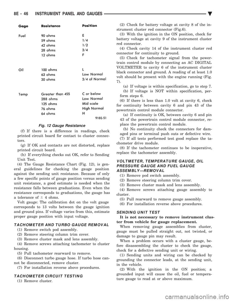
(4) The Gauge Resistance Chart (Fig. 12), is gen-
eral guidelines for checking the gauge position
against the sending unit resistance. Because of only
a few specific points of gauge position versus sending
unit resistance, a good estimate is needed when the
resistance falls between graduations. Even when the
resistance corresponds to graduations, the gauge has
a tolerance of 64 ohms.
Volt gauge: The calibration dot on the volt gauge
corresponds to 13 volts between the gauge ignition
and ground pins. If voltage varies from this, estimate
proper gauge position with input voltage.
TACHOMETER AND TURBO GAUGE REMOVAL
(1) Remove switch pod assembly.
(2) Remove steering column trim cover.
(3) Remove cluster mask and lens assembly.
(4) Remove screws attaching tachometer to cluster
housing. (5) Pull tachometer rearward to remove.
(6) Disconnect turbo gauge hose. If turbo hose can-
not be disconnected, remove cluster. (7) For installation reverse above procedures.
TACHOMETER CIRCUIT TESTING
(1) Remove cluster. (2) Check for battery voltage at cavity 8 of the in-
strument cluster red connector (Fig.6). (3) With the ignition in the ON position, check for
battery voltage at cavity 9 of the instrument cluster
red connector. (4) Check cavity 14 of the instrument cluster red
connector for continuity to ground. (5) Check for tachometer signal from the power-
train control module by connecting an AC DIGITAL
VOLTMETER to cavity 6 of the instrument cluster
black connector and ground. A reading of at least 1.0
volt should be present with the engine running (Fig.
7). (a) If voltage is within specification, go to step 7.
(b) If voltage is NOT within specification, per-
form steps 6.
(6) If there is less than 1.0 volt at cavity 6, check
for continuity between cavity 6 and pin 43 of the
powertrain control module connector. (a) If continuity is OK, between cavity 6 and pin
43 of the powertrain control module connector, re-
place the powertrain control module. (b) No continuity check the connectors for dam-
aged pins or terminal push outs or defective wire.
(7) If all tests performed test good replace the ta-
chometer drive module. (8) If the tachometer continues to be inoperative,
replace the tachometer assembly.
VOLTMETER, TEMPERATURE GAUGE, OIL PRESSURE GAUGE AND FUEL GAUGEASSEMBLYÐREMOVAL
(1) Remove pod switch assembly.
(2) Remove steering column trim cover.
(3) Remove cluster mask and lens assembly.
(4) Remove screws attaching gauge assembly to
cluster. (5) Pull rearward to remove gauge assembly.
(6) For installation reverse above procedures.
SENDING UNIT TEST
It is not necessary to remove instrument clus-
ter from vehicle for gauge replacement. When removing gauge assemblies from cluster,
gauge must be pulled straight out, not twisted, or
damage to gauge pin may result. When a problem occurs with a cluster gauge, be-
fore disassembling the cluster to check the gauge,
check for a defective sending unit or wiring. (1) Sending units and wiring can be checked by
grounding the connector leads, at the sending unit,
in the vehicle. (2) With the ignition in the ON position; a
grounded input will cause the oil, fuel or tempera-
ture gauge to read at or above maximum.
Fig. 12 Gauge Resistance
8E - 46 INSTRUMENT PANEL AND GAUGES Ä
Page 567 of 2438

AUDIO SYSTEM
CONTENTS
page page
ANTENNAS ............................ 20
COMPACT DISC PLAYER ................. 30 RADIOS
................................ 1
SPEAKERS ............................ 24
RADIOS INDEX
page page
Audio Diagnostic Test Procedures ............. 1
Description .............................. 1
Interference Elimination ..................... 1
Radio Removal AP Body Replacement ........ 19 Radio RemovalÐAA Body
.................. 18
Radio RemovalÐAC and AY Bodies .......... 18
Radio RemovalÐAG and AJ Bodies .......... 18
DESCRIPTION
For operation of the factory installed standard and
optional radios and the optional compact disc player,
refer to the Sound Systems Operating Instructions
Manual supplied with the vehicle. All vehicles are equipped with an Ignition-Off
Draw Connector which, is used when the vehicles are
originally shipped from the factory. This connector
which, is located near the battery, helps to prevent
battery discharge during storage. For specific connec-
tor type and location, refer to Group 8W, Wiring Di-
agrams. This connector is included in the radio memory cir-
cuitry and should be checked if the memory of time
or radio station programming is inoperative.
INTERFERENCE ELIMINATION
Some components are used on vehicles equipped
with a radio capacitor, to suppress radio frequency
interference/static. Capacitors are mounted in various locations, on the
generator either internal or external, internal to the
instrument cluster, and internal to the windshield
wiper motor. Ground straps are mounted from radio chassis to
instrument panel support structure, engine to cowl,
across engine mount on right hand side. On vehicles
with air conditioning there is a strap from evapora-
tor valve to cowl. These ground straps should be se-
curely tightened to assure good metal to metal
contact. Ground straps conduct very small high fre-
quency electrical signals to ground and require clean
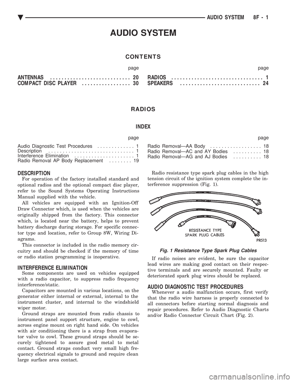
large surface area contact. Radio resistance type spark plug cables in the high
tension circuit of the ignition system complete the in-
terference suppression (Fig. 1).
If radio noises are evident, be sure the capacitor
lead wires are making good contact on their respec-
tive terminals and are securely mounted. Faulty or
deteriorated spark plug wires should be replaced.
AUDIO DIAGNOSTIC TEST PROCEDURES
Whenever a audio malfunction occurs, first verify
that the radio wire harness is properly connected to
all connectors before starting normal diagnosis and
repair procedures. Refer to Audio Diagnostic Charts
and/or Radio Connector Circuit Chart (Fig. 2).
Fig. 1 Resistance Type Spark Plug Cables
Ä AUDIO SYSTEM 8F - 1
Page 2003 of 2438

(3) Move selector lever on transaxle one detent
forward from full rearward position. This is selector
2 position.
(4) Read pressures on both gauges as throttle lever
on transaxle is moved from full clockwise position to
full counterclockwise position. (5) Line pressure should read 52 to 58 psi with
throttle lever clockwise and gradually increase, as le-
ver is moved counterclockwise, to 80 to 88 psi. (6) Lubrication pressure should be 10 to 25 psi
with lever clockwise and 10 to 35 psi with lever full
counterclockwise. (7) This tests pump output, pressure regulation,
and condition of rear clutch and lubrication hydrau-
lic circuits.
TEST THREE (SELECTOR IN D)
(1) Attach gauges to lineandkickdown release
ports (Fig. 3). (2) Operate engine at 1600 rpm for test.
(3) Move selector lever on transaxle two detents
forward from full rearward position. This is selector
D position.
(4) Read pressures on both gauges as throttle lever
on transaxle is moved from full clockwise position to
full counterclockwise position. (5) Line pressure should read 52 to 58 psi with
throttle lever clockwise and gradually increase, as le-
ver is moved counterclockwise to 80 to 88 psi. (6) Kickdown release is pressurized only in direct
drive and should be same as line pressure within 3
psi, up to kickdown point. (7) This tests pump output, pressure regulation,
and condition of rear clutch, front clutch, and hy-
draulic circuits.
TEST FOUR (SELECTOR IN REVERSE)
(1) Attach 300 psi gauge to low-reverseport (Fig.
3). (2) Operate engine at 1600 rpm for test.
(3) Move selector lever on transaxle four detents
forward from full rearward position. This is selector
R position.
(4) Low-reverse pressure should read 180 to 220
psi with throttle lever clockwise and gradually in-
crease, as lever is moved counterclockwise to 260 to
300 psi. (5) This tests pump output, pressure regulation,
and condition of front clutch and rear servo hydraulic
circuits. (6) Move selector lever on transaxle to Dposition
to check that low-reverse pressure drops to zero. (7) This tests for leakage into rear servo, due to
case porosity, which can cause reverse band burn
out.
TEST RESULT INDICATIONS
(1) If proper line pressure, minimum to maximum, is
found in any one test, the pump and pressure regulator
are working properly. (2) Low pressure in D, 1, and 2but correct pressure
in Rindicates rear clutch circuit leakage.
(3) Low pressure in D and Rbut correct pressure in
1 indicates front clutch circuit leakage.
(4) Low pressure in R and 1but correct pressure in
2 indicates rear servo circuit leakage.
(5) Low line pressure in all positions indicates a
defective pump, a clogged filter, or a stuck pressure
regulator valve.
GOVERNOR PRESSURE
Test only if transaxle shifts at wrong vehicle speeds
when throttle cable is correctly adjusted. (1) Connect a 0-150 psi pressure gauge to governor
pressure take-off point, located at lower right side of
case, below differential cover (Fig. 3). (2) Operate transaxle in third gear to read pres-
sures. The governor pressure should respond smoothly
to changes in mph and should return to 0 to 3 psi when vehicle is stopped. High pressure at
standstill (above 3 psi) will prevent the transaxle from
downshifting.
THROTTLE PRESSURE
No gauge port is provided for throttle pressure.
Incorrect throttle pressure should only be suspected if
part throttle upshift speeds are either delayed or occur
too early, with a correctly adjusted throttle cable.
Engine runaway on either upshifts or downshifts can
also be an indicator of incorrect (low) throttle pressure
setting, or misadjusted throttle cable. In no case should throttle pressure be adjusted until
the transaxle throttle cable adjustment has been veri-
fied to be correct.
CLUTCH AND SERVO AIR PRESSURE TESTS
A no drive condition might exist even with correct
fluid pressure, because of inoperative clutches or
bands. The inoperative units, clutches, bands, and
servos can be located through a series of tests by
substituting air pressure for fluid pressure (Fig. 4). The front and rear clutches, kickdown servo, and
low-reverse servo may be tested by applying air pres-
sure to their respective passages after the valve body assembly has been removed. To make
air pressure tests, proceed as follows: Compressed air supply must be free of all dirt
or moisture. Use a pressure of 30 psi. Remove oil pan and valve body See Disassembly-
Subassembly Removal .
FRONT CLUTCH
Apply air pressure to front clutch applypassage and
listen for a dull thudwhich indicates that front
Ä TRANSAXLE 21 - 43
Page 2055 of 2438

(5) This test checks pump output, pressure regula-
tion and condition of the low/reverse clutch hydraulic
circuit and shift schedule.
TEST TWO-SELECTOR IN DRIVE 2ND GEAR
(1) Attach gauge to the underdrive clutch tap.
(2) Move selector lever to the 3position.
(3) Allow vehicle wheels to turn and increase
throttle opening to achieve an indicated vehicle
speed of 30 mph. (4) Underdrive clutch pressure should read 110 to
145 psi. (5) This test checks the underdrive clutch hydrau-
lic circuit as well as the shift schedule.
TEST THREE-OVERDRIVE CLUTCH CHECK
(1) Attach gauge to the overdrive clutch tap.
(2) Move selector lever to the circle Dposition.
(3) Allow vehicle wheels to turn and increase
throttle opening to achieve an indicated vehicle
speed of 20 mph. (4) Overdrive clutch pressure should read 74 to 95
psi. (5) Move selector lever to the 3position and in-
crease indicated vehicle speed to 30 mph. (6) The vehicle should be in second gear and over-
drive clutch pressure should be less than 5 psi. (7) This test checks the overdrive clutch hydraulic
circuit as well as the shift schedule.
TEST FOUR-SELECTOR IN CIRCLE DRIVE, OVERDRIVE GEAR
(1) Attach gauge to the 2/4 clutch tap.
(2) Move selector lever to the circle Dposition.
(3) Allow vehicle front wheels to turn and increase
throttle opening to achieve an indicated vehicle
speed of 30 mph. (4) The 2/4 clutch pressure should read 75 to 95
psi. (5) This test checks the 2/4 clutch hydraulic circuit.
TEST FIVE-SELECTOR IN CIRCLE DRIVE,
OVERDRIVE
(1) Attach gauge to the torque converter clutch off
pressure tap. (2) Move selector lever to the circle Dposition.
(3) Allow vehicle wheels to turn and increase
throttle opening to achieve an indicated vehicle speed
of 50 mph.
CAUTION: Both wheels must turn at the same speed. (4) Torque converter clutch off pressure should be
less than 5 psi. (5) This test checks the torque converter clutch
hydraulic circuit.
TEST SIX-SELECTOR IN REVERSE
(1) Attach gauge to the reverse clutch tap.
(2) Move selector lever to the reverse position.
(3) Read reverse clutch pressure with output sta-
tionary (foot on brake) and throttle opened to achieve
1500 rpm. (4) Reverse clutch pressure should read 165 to 235
psi. (5) This test checks the reverse clutch hydraulic
circuit.
TEST RESULT INDICATIONS
(1) If proper line pressure is found in any one test,
the pump and pressure regulator are working properly. (2) Low pressure in all positions indicates a defec-
tive pump, a clogged filter, or a stuck pressure regula-
tor valve. (3) Clutch circuit leaks are indicated if pressures do
not fall within the specified pressure range. (4) If the overdrive clutch pressure is greater than 5
psi in step (6) of Test Three, a worn reaction shaft seal
ring is indicated.
CLUTCH AIR PRESSURE TESTS
Inoperative clutches can be located using a series of
tests by substituting air pressure for fluid pressure
(Figs. 2 and 3). The clutches may be tested by applying
air pressure to their respective passages after the valve
body has been removed and Tool 6056 has been in-
stalled. To make air pressure tests, proceed as follows: The compressed air supply must be free of all
dirt and moisture. Use a pressure of 30 psi. Remove oil pan and valve body. See Valve body
removal.
OVERDRIVE CLUTCH
Apply air pressure to the overdrive clutch apply
passage and watch for the push/pull piston to move
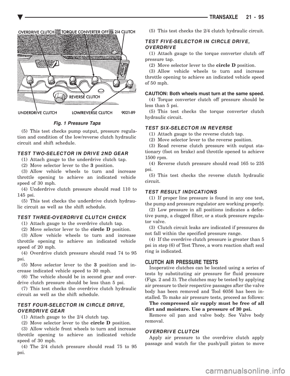
Fig. 1 Pressure Taps
Ä TRANSAXLE 21 - 95