coolant level CHEVROLET DYNASTY 1993 Service Manual
[x] Cancel search | Manufacturer: CHEVROLET, Model Year: 1993, Model line: DYNASTY, Model: CHEVROLET DYNASTY 1993Pages: 2438, PDF Size: 74.98 MB
Page 40 of 2438

LUBRICANTS AND GREASES
Lubricating grease is rated for quality and usage
by the NLGI. All approved products have the NLGI
symbol on the label. At the bottom NLGI symbol is the usage and qual-
ity identification letters. Wheel bearing lubricant is
identified by the letter ``G''. Chassis lubricant is iden-
tified by the letter ``L''. The letter following the us-
age letter indicates the quality of the lubricant. The
following symbols indicate the highest quality.
FLUID CAPACITIES
Fuel Tank
AP,AG and AJ ......................................53 L (14 gal.)
AA,AC and AY .....................................60 L (16 gal.)
AA-Flexible Fuel ..................................68 L (18 gal.)
Engine Oil
All.........................................................3.8 L (4.5 qts.)
Cooling System
2.2L ......................................................8.5 L (9.0 qts.)
2.5L ......................................................8.5 L (9.0 qts.)
3.0L ......................................................9.0 L (9.5 qts.)
3.3L ......................................................9.0 L (9.5 qts.)
3.8L ......................................................9.0 L (9.5 qts.)
Includes heater and coolant recovery bottle
Automatic Transaxle
Estimated Service Fill
ALL ......................................................3.8 L (4.0 qts.)
Overhaul Fill Capacity with Torque Converter
Empty
3-speed Fleet .......................................8.7 L (9.2 qts.)
3-speed .................................................8.2 L (8.8 qts.)
4-speed Electronic ................................9.4L (9.9 qts.)
Manual Transaxle
All ..........................................................9.4L (9.9 qts.)
Fill to bottom of fill hole.
Power Steering
All ...........................................................75L (1.5 pts.)
PARTS REQUIRING NO LUBRICATION
Many components on a Chrysler Corporation vehi-
cle require no periodic maintenance. Some compo-
nents are sealed and permanently lubricated. Rubber
bushings can deteriorate or limit damping ability if
lubricated. The following list of components require
no lubrication: ²
Air Pump
² Generator Bushings
² Drive Belts
² Drive Belt Idler/Tensioner Pulley
² Front Wheel Bearings
² Rubber Bushings
² Starter Bearings/Bushings
² Suspension Strut Bearings
² Throttle Control Cable
² Throttle Linkage
² Water Pump Bearings
JUMP STARTING PROCEDURE
WARNING: REVIEW ALL SAFETY PRECAUTIONS
AND WARNINGS IN GROUP 8A, BATTERY/START-
ING/CHARGING SYSTEMS DIAGNOSTICS. DO NOT JUMP START A FROZEN BATTERY, PER-
SONAL INJURY CAN RESULT. DO NOT JUMP START WHEN BATTERY INDICA-
TOR DOT IS YELLOW OR BRIGHT COLOR. DO NOT ALLOW JUMPER CABLE CLAMPS TO
TOUCH EACH OTHER WHEN CONNECTED TO A
BOOSTER SOURCE. DO NOT USE OPEN FLAME NEAR BATTERY.
REMOVE METALLIC JEWELRY WORN ON HANDS
OR WRISTS TO AVOID INJURY BY ACCIDENTAL
ARCHING OF BATTERY CURRENT. WHEN USING A HIGH OUTPUT BOOSTING DE-
VICE, DO NOT ALLOW BATTERY VOLTAGE TO EX-
CEED 16 VOLTS. REFER TO INSTRUCTIONS
PROVIDED WITH DEVICE BEING USED.
CAUTION: When using another vehicle as a
booster, do not allow vehicles to touch. Electrical
systems can be damaged on either vehicle.
TO JUMP START A DISABLED VEHICLE:
(1) Raise hood on disabled vehicle and visually in-
spect engine compartment for:
² Battery cable clamp condition, clean if necessary.
² Frozen battery.
² Yellow or bright color test indicator, if equipped.
² Low battery fluid level.
² Generator drive belt condition and tension.
² Fuel fumes or leakage, correct if necessary.
CAUTION: If the cause of starting problem on dis-
abled vehicle is severe, damage to booster vehicle
charging system can result.
(2) When using another vehicle as a booster
source, turn off all accessories, place gear selector in
park or neutral, set park brake and operate engine
at 1200 rpm.
NLGI SYMBOL
0 - 4 LUBRICATION AND MAINTENANCE Ä
Page 46 of 2438
ENGINE COOLING SYSTEM
WARNINGS AND PRECAUTIONS
WARNING: ANTIFREEZE IS AN ETHYLENE GLYCOL
BASE COOLANT AND IS HARMFUL IF SWAL-
LOWED OR INHALED. IF SWALLOWED, DRINK
TWO GLASSES OF WATER AND INDUCE VOMIT-
ING. IF INHALED, MOVE TO FRESH AIR AREA.
SEEK MEDICAL ATTENTION IMMEDIATELY. DO
NOT STORE IN OPEN OR UNMARKED CONTAIN-
ERS. WASH SKIN AND CLOTHING THOROUGHLY
AFTER COMING IN CONTACT WITH ETHYLENE
GLYCOL. KEEP OUT OF REACH OF CHILDREN. DISPOSE OF GLYCOL BASE COOLANT PROP-
ERLY, CONTACT YOUR DEALER OR GOVERNMENT
AGENCY FOR LOCATION OF COLLECTION CEN-
TER IN YOUR AREA. DO NOT OPEN A COOLING SYSTEM WHEN THE
ENGINE IS AT RUNNING TEMPERATURE, PER-
SONAL INJURY CAN RESULT. AVOID RADIATOR COOLING FAN WHEN ENGINE
COMPARTMENT RELATED SERVICE IS PER-
FORMED, PERSONAL INJURY CAN RESULT.
CAUTION: Do not use straight antifreeze as engine
coolant, inadequate engine running temperatures
can result. Do not operate vehicle without proper concentra-
tion of recommended ethylene glycol coolant, high
running temperatures and cooling system corrosion
can result.
The engine cooling system will develop internal
pressure of 97 to 123 kPa (14 to 18 psi) at normal op-
erating temperature. Allow the vehicle approxi-
mately one half hour to cool off before opening the
cooling system. As an indicator of pressure, squeeze
the upper radiator hose between index finger and
thumb. If it collapses with little effort the system
would have low internal pressure and should be safe
to open to the first safety notch of the radiator cap.
Refer to Group 7, Cooling System.
COOLING SYSTEM INSPECTION
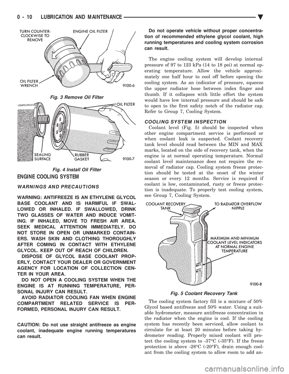
Coolant level (Fig. 5) should be inspected when
other engine compartment service is performed or
when coolant leak is suspected. Coolant recovery
tank level should read between the MIN and MAX
marks, located on the side of recovery tank, when the
engine is at normal operating temperature. Normal
coolant level maintenance does not require the re-
moval of radiator cap. Cooling system freeze protec-
tion should be tested at the onset of the winter
season or every 12 months. Service is required if
coolant is low, contaminated, rusty or freeze protec-
tion is inadequate. To properly test cooling system,
see Group 7, Cooling System.
The cooling system factory fill is a mixture of 50%
Glycol based antifreeze and 50% water. Using a suit-
able hydrometer, measure antifreeze concentration in
the radiator when the engine is cool. If the cooling
system has recently been serviced, allow coolant to
circulate for at least 20 minutes before taking hy-
drometer reading. Properly mixed coolant will pro-
tect the cooling system to -37ÉC (-35ÉF). If the freeze
protection is above -28ÉC (-20ÉF), drain enough cool-
ant from the cooling system to allow room to add an-
Fig. 3 Remove Oil Filter
Fig. 4 Install Oil Filter
Fig. 5 Coolant Recovery Tank
0 - 10 LUBRICATION AND MAINTENANCE Ä
Page 343 of 2438
COOLING SYSTEM
CONTENTS
page page
ACCESSORY DRIVE BELTS ............... 24
ENGINE BLOCK HEATER ................. 28
GENERAL INFORMATION .................. 1 SERVICE PROCEDURES
.................. 10
SPECIFICATIONS ....................... 29
GENERAL INFORMATION
Throughout this group, references may be made to
a particular vehicle by letter or number designation.
A chart showing the breakdown of these designations
is included in the Introduction Section at the front of
this service manual.
COOLING SYSTEM
The cooling system consists of an engine cooling
module, thermostat, coolant, a water pump to circu-
late the coolant. The engine cooling module may con-
sist of a radiator, electric fan motor, shroud, radiator
pressure cap, coolant reserve system, transmission oil
cooler, hoses, clamps, air condition condenser, trans-
mission oil lines and charge air cooler.
² When Engine is cold: Thermostat is closed, cooling
system has no flow through the radiator. The coolant
bypass flows through the engine only. ²
When Engine is warm: Thermostat is open, cooling
system has bypass flow and coolant flow through ra-
diator. Its primary purpose is to maintain engine temper-
ature in a range that will provide satisfactory engine
performance and emission levels under all expected
driving conditions. It also provides hot water (cool-
ant) for heater performance and cooling for auto-
matic transmission oil. It does this by transferring
heat from engine metal to coolant, moving this
heated coolant to the radiator, and then transferring
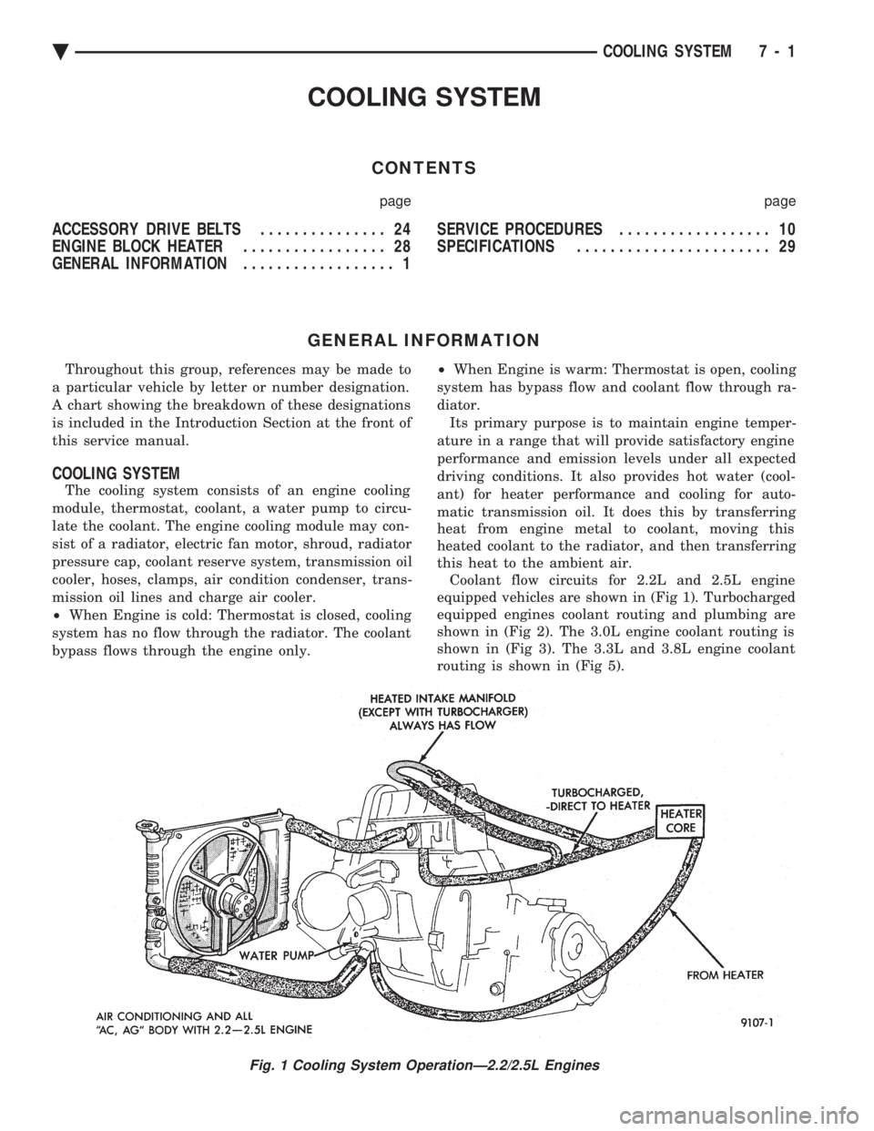
this heat to the ambient air. Coolant flow circuits for 2.2L and 2.5L engine
equipped vehicles are shown in (Fig 1). Turbocharged
equipped engines coolant routing and plumbing are
shown in (Fig 2). The 3.0L engine coolant routing is
shown in (Fig 3). The 3.3L and 3.8L engine coolant
routing is shown in (Fig 5).
Fig. 1 Cooling System OperationÐ2.2/2.5L Engines
Ä COOLING SYSTEM 7 - 1
Page 355 of 2438
(5) Install drive belt. See Accessory Drive Belts
this group. (6) Install right front lower fender shield.
(7) Refill Cooling System. See Refilling Cooling
System in this section.
ENGINE THERMOSTATS
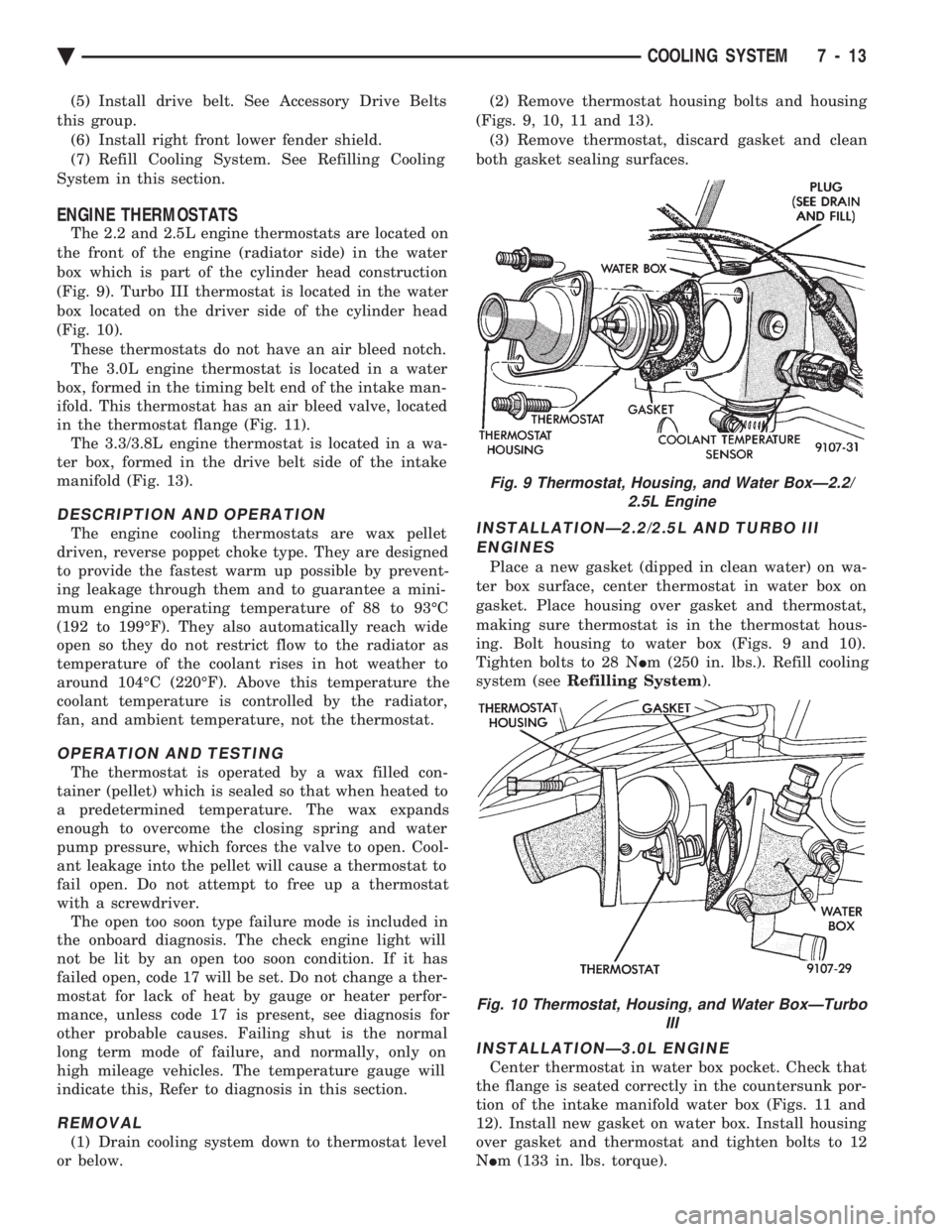
The 2.2 and 2.5L engine thermostats are located on
the front of the engine (radiator side) in the water
box which is part of the cylinder head construction
(Fig. 9). Turbo III thermostat is located in the water
box located on the driver side of the cylinder head
(Fig. 10). These thermostats do not have an air bleed notch.
The 3.0L engine thermostat is located in a water
box, formed in the timing belt end of the intake man-
ifold. This thermostat has an air bleed valve, located
in the thermostat flange (Fig. 11). The 3.3/3.8L engine thermostat is located in a wa-
ter box, formed in the drive belt side of the intake
manifold (Fig. 13).
DESCRIPTION AND OPERATION
The engine cooling thermostats are wax pellet
driven, reverse poppet choke type. They are designed
to provide the fastest warm up possible by prevent-
ing leakage through them and to guarantee a mini-
mum engine operating temperature of 88 to 93ÉC
(192 to 199ÉF). They also automatically reach wide
open so they do not restrict flow to the radiator as
temperature of the coolant rises in hot weather to
around 104ÉC (220ÉF). Above this temperature the
coolant temperature is controlled by the radiator,
fan, and ambient temperature, not the thermostat.
OPERATION AND TESTING
The thermostat is operated by a wax filled con-
tainer (pellet) which is sealed so that when heated to
a predetermined temperature. The wax expands
enough to overcome the closing spring and water
pump pressure, which forces the valve to open. Cool-
ant leakage into the pellet will cause a thermostat to
fail open. Do not attempt to free up a thermostat
with a screwdriver. The open too soon type failure mode is included in
the onboard diagnosis. The check engine light will
not be lit by an open too soon condition. If it has
failed open, code 17 will be set. Do not change a ther-
mostat for lack of heat by gauge or heater perfor-
mance, unless code 17 is present, see diagnosis for
other probable causes. Failing shut is the normal
long term mode of failure, and normally, only on
high mileage vehicles. The temperature gauge will
indicate this, Refer to diagnosis in this section.
REMOVAL
(1) Drain cooling system down to thermostat level
or below. (2) Remove thermostat housing bolts and housing
(Figs. 9, 10, 11 and 13). (3) Remove thermostat, discard gasket and clean
both gasket sealing surfaces.
INSTALLATIONÐ2.2/2.5L AND TURBO III ENGINES
Place a new gasket (dipped in clean water) on wa-
ter box surface, center thermostat in water box on
gasket. Place housing over gasket and thermostat,
making sure thermostat is in the thermostat hous-
ing. Bolt housing to water box (Figs. 9 and 10).
Tighten bolts to 28 N Im (250 in. lbs.). Refill cooling
system (see Refilling System ).
INSTALLATIONÐ3.0L ENGINE
Center thermostat in water box pocket. Check that
the flange is seated correctly in the countersunk por-
tion of the intake manifold water box (Figs. 11 and
12). Install new gasket on water box. Install housing
over gasket and thermostat and tighten bolts to 12
N Im (133 in. lbs. torque).
Fig. 9 Thermostat, Housing, and Water BoxÐ2.2/
2.5L Engine
Fig. 10 Thermostat, Housing, and Water BoxÐTurbo III
Ä COOLING SYSTEM 7 - 13
Page 357 of 2438
-37ÉC (-35ÉF) to -59ÉC (-50ÉF). If it looses color or
becomes contaminated, drain, flush, and replace with
fresh properly mixed solution.
SERVICE
Coolant should be changed at 52,500 miles or three
years, whichever occurs first, then every two years or
30,000 miles.
ROUTINE LEVEL CHECK
Do not remove radiator cap for routine coolant
level inspections. The coolant reserve system provides a quick visual
method for determining the coolant level without re-
moving the radiator cap. Simply observe, with the
engine idling and warmed up to normal operating
temperature, that the level of the coolant in the reserve
tank (Figs. 5 and 6) is between the minimum and
maximum marks.
ADDING ADDITIONAL COOLANT
The radiator cap should not be removed. When
additional coolant is needed to maintain this level, it
should be added to the coolant reserve tank. Use only
50/50 concentration of ethylene glycol type antifreeze
and water.
SERVICE COOLANT LEVEL
The cooling system is closed and designed to main-
tain coolant level to the top of the radiator. When servicing requires a coolant level check in the
radiator, the engine must be offand notunder pres-
sure. Drain several ounces of coolant from the radiator
drain cock while observing the Coolant Recovery Sys-
tem (CRS) Tank. Coolant level in the CRS tank should
drop slightly. Then remove the radiator cap. The radia-
tor should be full to the top. If not, and the coolant level
in the CRS tank is at the MIN mark there is a air leak
in the CRS system. Check hose or hose connections to
the CRS tank, radiator filler neck or the pressure cap
seal to the radiator filler neck for leaks.
LOW COOLANT LEVEL AERATION
Low coolant level in a cross flow radiator will equal-
ize in both tanks with engine off. With engine at
running operating temperature the high pressure inlet
tank runs full and the low pressure outlet tank drops.
If this level drops below the top of the transmission oil
cooler, air will be sucked into the water pump:
² Transmission oil will become hotter.
² High reading shown on the temperature gauge.
² Air in the coolant will also cause loss of flow through
the heater.
² Exhaust gas leaks into the coolant can also cause the
same problems.
DEAERATION
Air can only be removed from the system by gather-
ing under the pressure cap. On the next heat up it will
be pushed past the pressure cap into the CRS tank by
thermal expansion of the coolant. It then escapes to the
atmosphere in the CRS tank and is replaced with solid
coolant on cool down.
COOLING SYSTEM DRAIN, CLEAN, FLUSH AND
REFILL
Drain, flush, and fill the cooling system at the
mileage or time intervals specified in the Maintenance
Schedule in this Group. If the solution is dirty or rusty
or contains a considerable amount of sediment, clean
and flush with a reliable cooling system cleaner. Care
should be taken in disposing of the used engine coolant
from your vehicle. Check governmental regulations for
disposal of used engine coolant.
DRAINING
To drain cooling system move temperature selector
for heater to full heat with engine running (to provide
vacuum for actuation). Without removing radiator
pressure cap and with system not under pres-
sure, Shut engine off and open draincock. The coolant
reserve tank (Fig. 5) should empty first, then remove
radiator pressure cap. (if not, see Testing Cooling
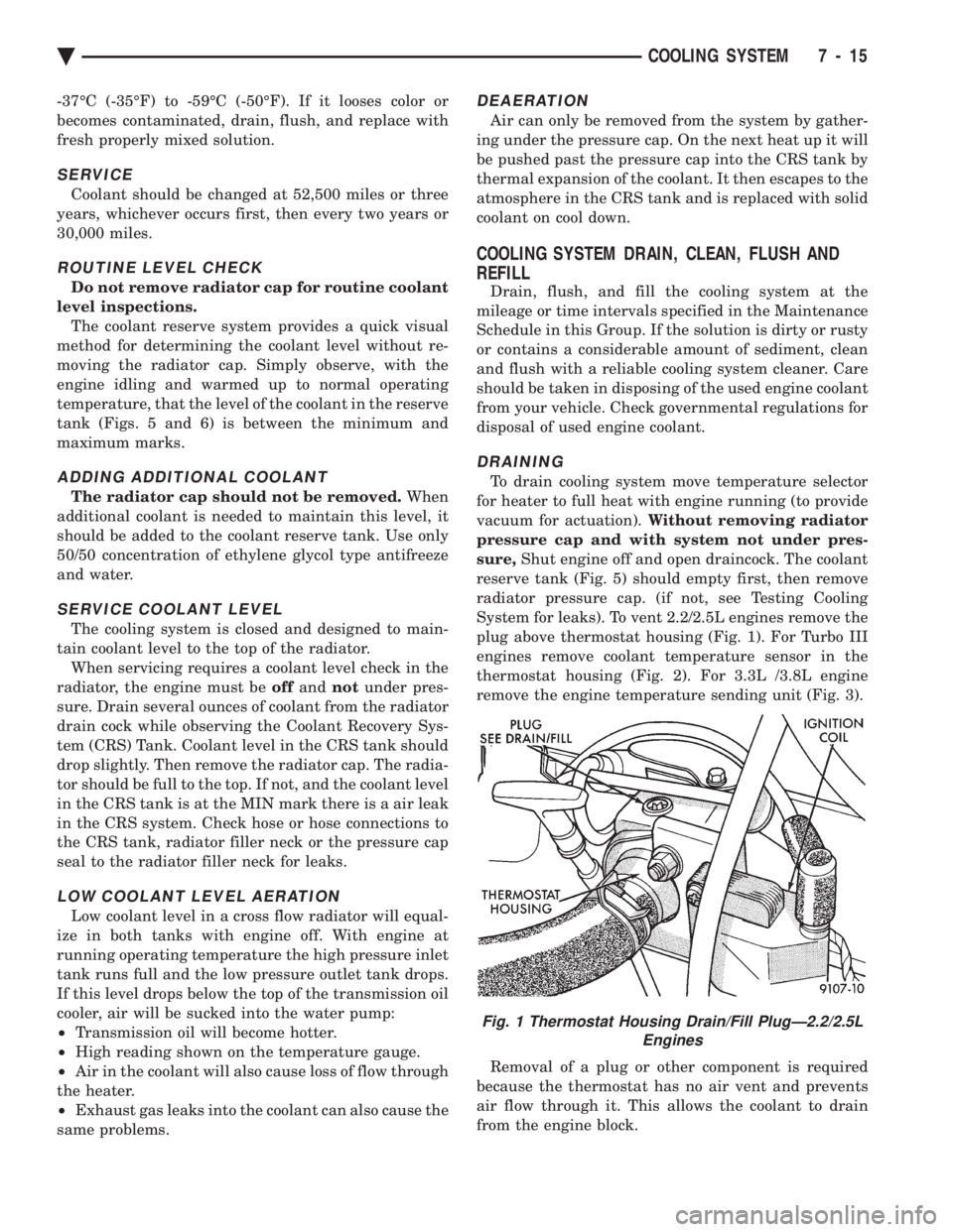
System for leaks). To vent 2.2/2.5L engines remove the
plug above thermostat housing (Fig. 1). For Turbo III
engines remove coolant temperature sensor in the
thermostat housing (Fig. 2). For 3.3L /3.8L engine
remove the engine temperature sending unit (Fig. 3).
Removal of a plug or other component is required
because the thermostat has no air vent and prevents
air flow through it. This allows the coolant to drain
from the engine block.
Fig. 1 Thermostat Housing Drain/Fill PlugÐ2.2/2.5L Engines
Ä COOLING SYSTEM 7 - 15
Page 358 of 2438
CLEANING
Drain cooling system (see: Draining Cooling Sys-
tem ) and refill with clean water (see: Refilling
Cooling System ). Run engine with radiator cap in-
stalled until upper radiator hose is hot. Stop engine
and drain water from system. If water is dirty, fill,
run and drain system again until water runs clear.
REVERSE FLUSHING
Reverse flushing of the cooling system is the forc-
ing of water through the cooling system, using air
pressure in a direction opposite to that of the normal
flow of water. This is only necessary with dirty sys-
tems and evidence of partial plugging.
RADIATOR Drain cooling system and remove radiator hoses
from engine. Install suitable flushing gun in radiator
lower hose. Fill radiator with clean water and turn
on air in short blasts. CAUTION: Internal radiator pressure must not ex-
ceed 138 kPa (20 psi) as damage to radiator may re-
sult. Continue this procedure until water runs clear.
ENGINE
Drain radiator (see: Draining Cooling System )
and remove hoses from radiator. Remove engine
thermostat and reinstall thermostat housing. Install
suitable flushing gun to thermostat housing hose.
Turn on water, and when engine is filled, turn on
air, but no higher than 138 kPa (20 psi) in short
blasts. Allow engine to fill between blasts of air.
Continue this procedure until water runs clean. In-
stall thermostat using a new housing gasket. Fill
cooling system (See Refilling Cooling System ).
CHEMICAL CLEANING
One type of corrosion encountered with aluminum
cylinder heads is aluminum hydroxide deposits. Cor-
rosion products are carried to the radiator and depos-
ited when cooled off. They appear as dark grey when
wet and white when dry. This corrosion can be re-
moved with a two part cleaner (oxalic acid and neu-
tralizer) available in auto parts outlets. Follow
manufacturers directions for use.
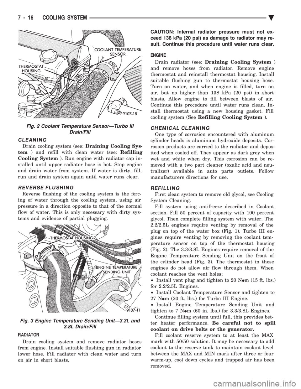
REFILLING
First clean system to remove old glycol, see Cooling
System Cleaning. Fill system using antifreeze described in Coolant
section. Fill 50 percent of capacity with 100 percent
glycol. Then complete filling system with water. The
2.2/2.5L engines require venting by removal of the
plug on top of the water box (Fig. 1). Turbo III en-
gines require venting by removing the coolant tem-
perature sensor on top of the thermostat housing
(Fig. 2). The 3.3/3.8L Engines require removal of the
Engine Temperature Sending Unit on the front of
the cylinder head (Fig. 3). The thermostat in these
engines do not allow air flow through them. When
coolant reaches the vent holes;
² Install vent plug and tighten to 20 N Im (15 ft. lbs.)
for 2.2/2.5L Engines.
² Install Coolant Temperature Sensor and tighten to
27 N Im (20 ft. lbs.) for Turbo III Engine.
² Install Engine Temperature Sending Unit and
tighten to 7 N Im (60 in. lbs.) for 3.3/3.8L Engines.
Continue filling system until full, this provides bet-
ter heater performance. Be careful not to spill
coolant on drive belts or the generator. Fill coolant reserve system to at least the MAX
mark with 50/50 solution. It may be necessary to add
coolant to the reserve tank to maintain coolant level
between the MAX and MIN mark after three or four
warm-up, cool down cycles and trapped air has been
removed.
Fig. 2 Coolant Temperature SensorÐTurbo III Drain/Fill
Fig. 3 Engine Temperature Sending UnitÐ3.3L and 3.8L Drain/Fill
7 - 16 COOLING SYSTEM Ä
Page 359 of 2438
TESTING SYSTEM FOR LEAKS
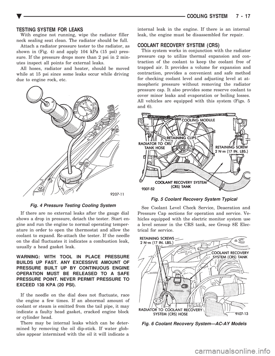
With engine not running, wipe the radiator filler
neck sealing seat clean. The radiator should be full. Attach a radiator pressure tester to the radiator, as
shown in (Fig. 4) and apply 104 kPa (15 psi) pres-
sure. If the pressure drops more than 2 psi in 2 min-
utes inspect all points for external leaks. All hoses, radiator and heater, should be moved
while at 15 psi since some leaks occur while driving
due to engine rock, etc.
If there are no external leaks after the gauge dial
shows a drop in pressure, detach the tester. Start en-
gine and run the engine to normal operating temper-
ature in order to open the thermostat and allow the
coolant to expand. Re-attach the tester. If the needle
on the dial fluctuates it indicates a combustion leak,
usually a head gasket leak.
WARNING: WITH TOOL IN PLACE PRESSURE
BUILDS UP FAST. ANY EXCESSIVE AMOUNT OF
PRESSURE BUILT UP BY CONTINUOUS ENGINE
OPERATION MUST BE RELEASED TO A SAFE
PRESSURE POINT. NEVER PERMIT PRESSURE TO
EXCEED 138 KPA (20 PSI).
If the needle on the dial does not fluctuate, race
the engine a few times. If an abnormal amount of
coolant or steam is emitted from the tail pipe, it may
indicate a faulty head gasket, cracked engine block
or cylinder head. There may be internal leaks which can be deter-
mined by removing the oil dip-stick. If water glob-
ules appear intermixed with the oil it will indicate a internal leak in the engine. If there is an internal
leak, the engine must be disassembled for repair.
COOLANT RECOVERY SYSTEM (CRS)
This system works in conjunction with the radiator
pressure cap to utilize thermal expansion and con-
traction of the coolant to keep the coolant free of
trapped air. It provides a volume for expansion and
contraction, provides a convenient and safe method
for checking coolant level and adjusting level at at-
mospheric pressure without removing the radiator
pressure cap. It also provides some reserve coolant to
cover minor leaks and evaporation or boiling losses.
All vehicles are equipped with this system (Figs. 5
and 6).
See Coolant Level Check Service, Deaeration and
Pressure Cap sections for operation and service. Ve-
hicles equipped with the electric monitor system use
a level sensor in the CRS tank, see Group 8E Elec-
trical for service.
Fig. 4 Pressure Testing Cooling System
Fig. 5 Coolant Recovery System Typical
Fig. 6 Coolant Recovery SystemÐAC-AY Models
Ä COOLING SYSTEM 7 - 17
Page 362 of 2438
(2) Remove radiator pressure cap when engine is
cold, Idle engine until thermostat opens, you should
observe coolant flow while looking down the filler
neck. Once flow is detected install radiator pressure
cap.
RADIATOR
REMOVAL
(1) Disconnect negative battery cable from battery.
WARNING: DO NOT REMOVE THE CYLINDER
BLOCK PLUG OR THE RADIATOR DRAINCOCK
WITH THE SYSTEM HOT AND UNDER PRESSURE
BECAUSE SERIOUS BURNS FROM COOLANT CAN
OCCUR.
(2) Drain cooling system. Refer to Draining Cool-
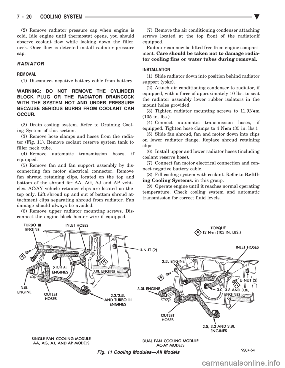
ing System of this section. (3) Remove hose clamps and hoses from the radia-
tor (Fig. 11). Remove coolant reserve system tank to
filler neck tube. (4) Remove automatic transmission hoses, if
equipped. (5) Remove fan and fan support assembly by dis-
connecting fan motor electrical connector. Remove
fan shroud retaining clips, located on the top and
bottom of the shroud for AA, AG, AJ and AP vehi-
cles. AC/AY vehicle retainer clips are located on the
top only. Lift shroud up and out of bottom shroud at-
tachment clips separating shroud from radiator. Fan
damage should always be avoided. (6) Remove upper radiator mounting screws. Dis-
connect the engine block heater wire if equipped. (7) Remove the air conditioning condenser attaching
screws located at the top front of the radiator,if
equipped. Radiator can now be lifted free from engine compart-
ment. Care should be taken not to damage radia-
tor cooling fins or water tubes during removal.
INSTALLATION
(1) Slide radiator down into position behind radiator
support (yoke). (2) Attach air conditioning condenser to radiator, if
equipped, with a force of approximately 10 lbs. to seat
the radiator assembly lower rubber isolators in the
mount holes provided. (3) Tighten radiator mounting screws to 11.9N Im
(105 in. lbs.). (4) Connect automatic transmission hoses, if
equipped. Tighten hose clamps to 4 N Im (35 in. lbs.).
(5) Slide fan shroud, fan and motor down into clips
on lower radiator flange. Replace shroud retaining
clips. (6) Install upper and lower radiator hoses (including
coolant reserve hose). (7) Connect fan motor electrical connection and con-
nect negative battery cable. (8) Fill cooling system with coolant. Refer to Refill-
ing Cooling Systems. in this group.
(9) Operate engine until it reaches normal operating
temperature. Check cooling system and automatic
transmission for correct fluid levels.
Fig. 11 Cooling ModulesÐAll Models
7 - 20 COOLING SYSTEM Ä
Page 370 of 2438
ENGINE BLOCK HEATER
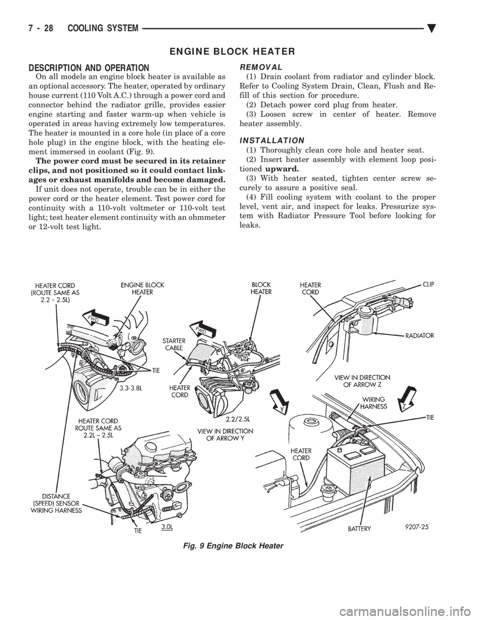
DESCRIPTION AND OPERATION
On all models an engine block heater is available as
an optional accessory. The heater, operated by ordinary
house current (110 Volt A.C.) through a power cord and
connector behind the radiator grille, provides easier
engine starting and faster warm-up when vehicle is
operated in areas having extremely low temperatures.
The heater is mounted in a core hole (in place of a core
hole plug) in the engine block, with the heating ele-
ment immersed in coolant (Fig. 9). The power cord must be secured in its retainer
clips, and not positioned so it could contact link-
ages or exhaust manifolds and become damaged. If unit does not operate, trouble can be in either the
power cord or the heater element. Test power cord for
continuity with a 110-volt voltmeter or 110-volt test
light; test heater element continuity with an ohmmeter
or 12-volt test light.
REMOVAL
(1) Drain coolant from radiator and cylinder block.
Refer to Cooling System Drain, Clean, Flush and Re-
fill of this section for procedure. (2) Detach power cord plug from heater.
(3) Loosen screw in center of heater. Remove
heater assembly.
INSTALLATION
(1) Thoroughly clean core hole and heater seat.
(2) Insert heater assembly with element loop posi-
tioned upward.
(3) With heater seated, tighten center screw se-
curely to assure a positive seal. (4) Fill cooling system with coolant to the proper
level, vent air, and inspect for leaks. Pressurize sys-
tem with Radiator Pressure Tool before looking for
leaks.
Fig. 9 Engine Block Heater
7 - 28 COOLING SYSTEM Ä
Page 423 of 2438
² To set DAY of WEEK, press TIME button. An ar-
row will appear on the display and point to the Day.
Press and hold the SET button to move the day for-
ward or INFO button to move it backward.
² To set DAY of MONTH, press TIME button. The
arrow will point to Date. Press and hold the SET
button to advance the date or INFO button to move
it backwards.
² To set MONTH of YEAR, press TIME button. The
arrow will point to the Month. Press and hold the
SET button to advance the Month forward or INFO
button to move backward. TEMP button, pressing the Temp button will dis-
play:
² The temperature outside the vehicle
² Vehicle direction define by an eight point compass
If Compass has lost calibration or not receiving
good information from the engine compartment node,
an asterisk (*) will flash on the display and the word
calibrate will appear. Refer to Compass Calibration. FUEL BUTTON, WILL DISPLAY:
² Pressing FUEL button the first time will show, the
estimated number of miles that can be driven with
the remaining fuel. The destination to empty indica-
tion will vary every few seconds as the amount of
fuel and fuel efficiency is calculated. This function
can not be reset.
² Pressing the FUEL button second time; will dis-
play the fuel consumed.
²
Pressing the FUEL button third time; will display
the average fuel economy in miles per gallon since last
reset. The display will be updated every 16 seconds.
² Pressing the FUEL button forth time, the current
fuel economy will be displayed. The current fuel
economy will be up updated every two seconds.
² To reset Fuel consumed, press SET button until
the fuel consumed message is displayed and then
within five seconds press SET button.
² To reset AVERAGE FUEL ECONOMY, press the
FUEL button until average fuel economy is displayed
and within five seconds press SET button. TRIP RESET, press FUEL button and wait four
seconds press the SET button twice. This clears all
trip information and the message Trip Reset will be
displayed. This will occur only if a reset function is
currently being displayed. The reset functions:
² Fuel consumed
² Average fuel economy message
INFO button, will active a MONITORED SYS-
TEMS OK message on display if all monitored sys-
tems are operating properly. If a problem is detected,
the appropriate message will be displayed. SET button, will clear the various functions after
they have been displayed. It is used to enter the
clock set or compass variance modes. This button is
also used to reset certain trip computer functions and
the maintenance reminder message.
The EVIC display may be turned off by pressing the
TIME and SET buttons at the same time. Pressing the
buttons a second time will restore the display.
EVIC INFORMATION SOURCES
The EVIC monitors information provided by the
body controller, engine compartment node and pow-
ertrain control module. Refer to Body Diagnostic Test
Procedure Manual for test procedures. The Body Controller is a micro-controller unit
which, informs the EVIC overhead console via the
CCD bus of:
² Time of day
² Day of week
² Day of month
² Month of year
² Fuel range
² Fuel consumed
² Fuel efficiency
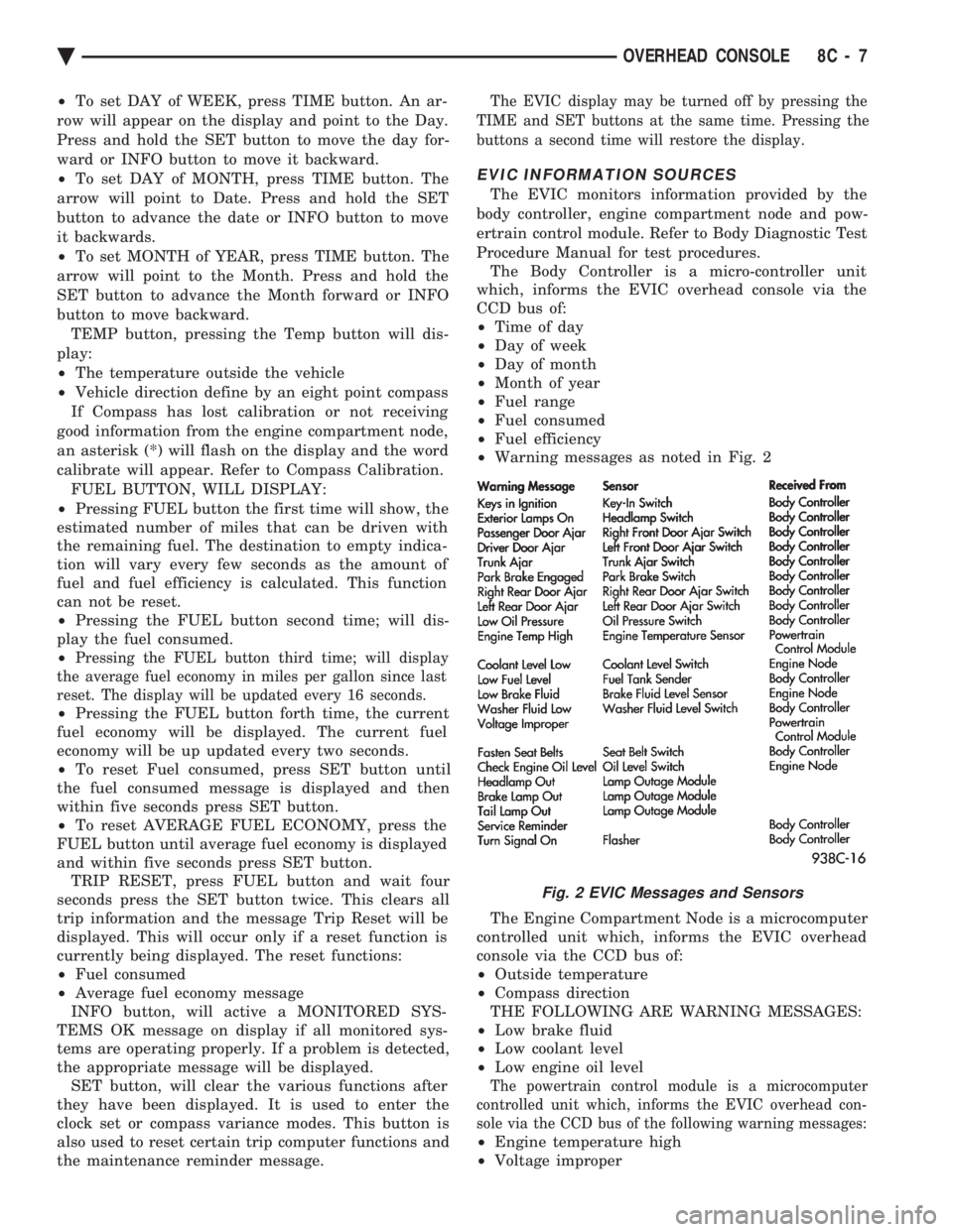
² Warning messages as noted in Fig. 2
The Engine Compartment Node is a microcomputer
controlled unit which, informs the EVIC overhead
console via the CCD bus of:
² Outside temperature
² Compass direction
THE FOLLOWING ARE WARNING MESSAGES:
² Low brake fluid
² Low coolant level
² Low engine oil level
The powertrain control module is a microcomputer
controlled unit which, informs the EVIC overhead con-
sole via the CCD bus of the following warning messages:
² Engine temperature high
² Voltage improper
Fig. 2 EVIC Messages and Sensors
Ä OVERHEAD CONSOLE 8C - 7