water pump CHEVROLET DYNASTY 1993 Service Manual
[x] Cancel search | Manufacturer: CHEVROLET, Model Year: 1993, Model line: DYNASTY, Model: CHEVROLET DYNASTY 1993Pages: 2438, PDF Size: 74.98 MB
Page 40 of 2438

LUBRICANTS AND GREASES
Lubricating grease is rated for quality and usage
by the NLGI. All approved products have the NLGI
symbol on the label. At the bottom NLGI symbol is the usage and qual-
ity identification letters. Wheel bearing lubricant is
identified by the letter ``G''. Chassis lubricant is iden-
tified by the letter ``L''. The letter following the us-
age letter indicates the quality of the lubricant. The
following symbols indicate the highest quality.
FLUID CAPACITIES
Fuel Tank
AP,AG and AJ ......................................53 L (14 gal.)
AA,AC and AY .....................................60 L (16 gal.)
AA-Flexible Fuel ..................................68 L (18 gal.)
Engine Oil
All.........................................................3.8 L (4.5 qts.)
Cooling System
2.2L ......................................................8.5 L (9.0 qts.)
2.5L ......................................................8.5 L (9.0 qts.)
3.0L ......................................................9.0 L (9.5 qts.)
3.3L ......................................................9.0 L (9.5 qts.)
3.8L ......................................................9.0 L (9.5 qts.)
Includes heater and coolant recovery bottle
Automatic Transaxle
Estimated Service Fill
ALL ......................................................3.8 L (4.0 qts.)
Overhaul Fill Capacity with Torque Converter
Empty
3-speed Fleet .......................................8.7 L (9.2 qts.)
3-speed .................................................8.2 L (8.8 qts.)
4-speed Electronic ................................9.4L (9.9 qts.)
Manual Transaxle
All ..........................................................9.4L (9.9 qts.)
Fill to bottom of fill hole.
Power Steering
All ...........................................................75L (1.5 pts.)
PARTS REQUIRING NO LUBRICATION
Many components on a Chrysler Corporation vehi-
cle require no periodic maintenance. Some compo-
nents are sealed and permanently lubricated. Rubber
bushings can deteriorate or limit damping ability if
lubricated. The following list of components require
no lubrication: ²
Air Pump
² Generator Bushings
² Drive Belts
² Drive Belt Idler/Tensioner Pulley
² Front Wheel Bearings
² Rubber Bushings
² Starter Bearings/Bushings
² Suspension Strut Bearings
² Throttle Control Cable
² Throttle Linkage
² Water Pump Bearings
JUMP STARTING PROCEDURE
WARNING: REVIEW ALL SAFETY PRECAUTIONS
AND WARNINGS IN GROUP 8A, BATTERY/START-
ING/CHARGING SYSTEMS DIAGNOSTICS. DO NOT JUMP START A FROZEN BATTERY, PER-
SONAL INJURY CAN RESULT. DO NOT JUMP START WHEN BATTERY INDICA-
TOR DOT IS YELLOW OR BRIGHT COLOR. DO NOT ALLOW JUMPER CABLE CLAMPS TO
TOUCH EACH OTHER WHEN CONNECTED TO A
BOOSTER SOURCE. DO NOT USE OPEN FLAME NEAR BATTERY.
REMOVE METALLIC JEWELRY WORN ON HANDS
OR WRISTS TO AVOID INJURY BY ACCIDENTAL
ARCHING OF BATTERY CURRENT. WHEN USING A HIGH OUTPUT BOOSTING DE-
VICE, DO NOT ALLOW BATTERY VOLTAGE TO EX-
CEED 16 VOLTS. REFER TO INSTRUCTIONS
PROVIDED WITH DEVICE BEING USED.
CAUTION: When using another vehicle as a
booster, do not allow vehicles to touch. Electrical
systems can be damaged on either vehicle.
TO JUMP START A DISABLED VEHICLE:
(1) Raise hood on disabled vehicle and visually in-
spect engine compartment for:
² Battery cable clamp condition, clean if necessary.
² Frozen battery.
² Yellow or bright color test indicator, if equipped.
² Low battery fluid level.
² Generator drive belt condition and tension.
² Fuel fumes or leakage, correct if necessary.
CAUTION: If the cause of starting problem on dis-
abled vehicle is severe, damage to booster vehicle
charging system can result.
(2) When using another vehicle as a booster
source, turn off all accessories, place gear selector in
park or neutral, set park brake and operate engine
at 1200 rpm.
NLGI SYMBOL
0 - 4 LUBRICATION AND MAINTENANCE Ä
Page 58 of 2438
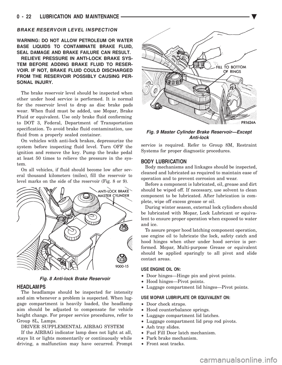
BRAKE RESERVOIR LEVEL INSPECTION
WARNING: DO NOT ALLOW PETROLEUM OR WATER
BASE LIQUIDS TO CONTAMINATE BRAKE FLUID,
SEAL DAMAGE AND BRAKE FAILURE CAN RESULT.
RELIEVE PRESSURE IN ANTI-LOCK BRAKE SYS-
TEM BEFORE ADDING BRAKE FLUID TO RESER-
VOIR. IF NOT, BRAKE FLUID COULD DISCHARGED
FROM THE RESERVOIR POSSIBLY CAUSING PER-
SONAL INJURY.
The brake reservoir level should be inspected when
other under hood service is performed. It is normal
for the reservoir level to drop as disc brake pads
wear. When fluid must be added, use Mopar, Brake
Fluid or equivalent. Use only brake fluid conforming
to DOT 3, Federal, Department of Transportation
specification. To avoid brake fluid contamination, use
fluid from a properly sealed container. On vehicles with anti-lock brakes, depressurize the
system before inspecting fluid level. Turn OFF the
ignition and remove the key. Pump the brake pedal
at least 50 times to relieve the pressure in the sys-
tem.
On all vehicles, if fluid should become low after sev-
eral thousand kilometers (miles), fill the reservoir to
level marks on the side of the reservoir (Fig. 8 or 9).
HEADLAMPS
The headlamps should be inspected for intensity
and aim whenever a problem is suspected. When lug-
gage compartment is heavily loaded, the headlamp
aim should be adjusted to compensate for vehicle
height change. For proper service procedures, refer to
Group 8L, Lamps. DRIVER SUPPLEMENTAL AIRBAG SYSTEM
If the AIRBAG indicator lamp does not light at all,
stays lit or lights momentarily or continuously while
driving, a malfunction may have occurred. Prompt service is required. Refer to Group 8M, Restraint
Systems for proper diagnostic procedures.
BODY LUBRICATION
Body mechanisms and linkages should be inspected,
cleaned and lubricated as required to maintain ease of
operation and to prevent corrosion and wear. Before a component is lubricated, oil, grease and dirt
should be wiped off. If necessary, use solvent to clean
component to be lubricated. After lubrication is com-
plete, wipe off excess grease or oil. During winter season, external lock cylinders should
be lubricated with Mopar, Lock Lubricant or equiva-
lent to ensure proper operation when exposed to water
and ice. To assure proper hood latching component operation,
use engine oil to lubricate the lock, safety catch and
hood hinges when other under hood service is per-
formed. Mopar, Multi-purpose Grease or equivalent
should be applied sparingly to all pivot and slide
contact areas.
USE ENGINE OIL ON:
² Door hingesÐHinge pin and pivot points.
² Hood hingesÐPivot points.
² Luggage compartment lid hingesÐPivot points.
USE MOPAR LUBRIPLATE OR EQUIVALENT ON:
² Door check straps.
² Hood counterbalance springs.
² Luggage compartment lid latches.
² Luggage compartment lid prop rod pivots.
² Ash tray slides.
² Fuel Fill Door latch mechanism.
² Park brake mechanism.
² Front seat tracks.
Fig. 8 Anti-lock Brake Reservoir
Fig. 9 Master Cylinder Brake ReservoirÐExcept
Anti-lock
0 - 22 LUBRICATION AND MAINTENANCE Ä
Page 136 of 2438
(3) Check solenoid to volume canister joint.
² Front strut to solenoid valve connection.
² Rear spring to solenoid valve connection.
(4) Check air line for ruptures, cuts, splits or heat
damage. Use a soap and water solution or a liquid de-
veloped for leak detection.
SYSTEM OPERATION
ENGINE RUN OPERATION
The system will compensate for load
addition/removal when.
² The trunk and all doors are closed.
² The engine speed exceeds 600 R.P.M.
² Throttle angle is less than 65 degrees.
² The brake is not applied.
² You are not cornering above 10 mph.
² There is not a charging system problem with the
vehicle.
ENGINE OFF OPERATION
After passengers/load is removed from the vehicle
the system will correct the vehicle attitude after:
² The trunk and all doors are closed.
² The ignition switch is in the OFF position.
Opening the a door or trunk wakes up the body
computer and the air suspension module. The air
suspension system is now capable of leveling, if
required.
LONG TERM IGNITION OFF OPERATION
The system is capable of one an additional leveling
cycle. After 2 continuous hours of ignition key off and
no door open or trunk open activities. This feature is
implemented to eliminate possible ice freeze-up be-
tween the tire and the inner fender shield.
SYSTEM OPERATION INHIBITORS
The air suspension system is inhibited when:
² The trunk is open.
² A door(s) is/are open.
² The brake pedal is engaged.
² The throttle is at the wide open position.
² The charging system fails.
The maximum compressor pump or exhaust
time is 3 minutes.
SYSTEM FAILURES
Vehicles equipped with air suspension and overhead
console. Will alert the driver of an air suspension
system malfunction. A warning Check Air Suspension
will appear on the overhead console screen.
SAFETY CONCERNS
WARNING: REAR AIR SPRINGS MUST BE DEFLATED
BEFORE BEING REMOVED FROM THE VEHICLE.
WARNING: OPEN TRUNK, OR DOOR(S) OR REMOVE
GROUND STRAP FROM BATTERY BEFORE HOIST-
ING OR JACKING A VEHICLE DURING MECHANICAL
REPAIRS.
WARNING: IF THE VEHICLE NEEDS SERVICE OR
REPAIR OF THE REAR SHOCK ABSORBERS OR
REAR AXLE PIVOT BUSHINGS. THE REAR AIR
SPRINGS MUST HAVE THE AIR PRESSURE RE-
MOVED BEFORE THE VEHICLE CAN BE SERVICED
SAFELY.
SHIPPING MODE
(1) Removing shipping height signal for customer
use.
² Use DRB II tester and 1991 Chassis (Air Suspen-
sion) service cartridge.
² Follow DRB II requirements to cancel shipping
height message in the body computer.
² Connect the Ignition Off Draw (I.O.D.) circuit.
The connection of the IOD circuit will cancel
the Shipping height signal. (2) Return to shipping height.
² Set shipping command in the body computer using
the DRB II and the 1991 Chassis (Air suspension)
service cartridge.
² Disconnect the I.O.D. connector.
DIAGNOSIS
INITIAL DIAGNOSTIC CHECK
(1) Check for blown or missing fuses.
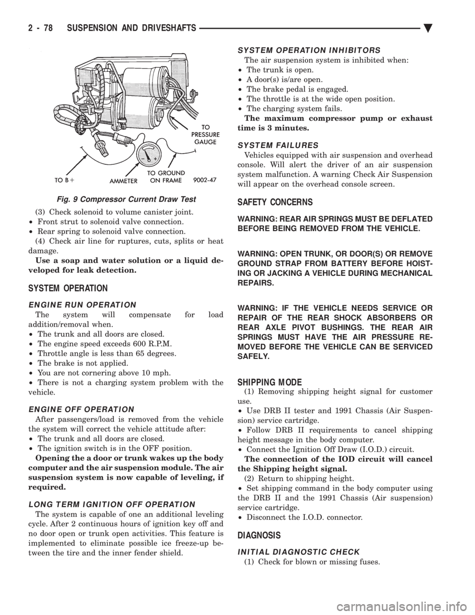
Fig. 9 Compressor Current Draw Test
2 - 78 SUSPENSION AND DRIVESHAFTS Ä
Page 239 of 2438
Brake Warning Lamp may indicate reduced
braking ability. The following procedure should
be used to test drive an ABS complaint:(1) Ignition on. Turn the ignition to the ON position
without starting the car and wait until the Red Brake
Warning Lamp and Amber Anti-Lock Warning Lamp
turn off. This will allow the pump to charge the
accumulator to operating pressure. If the warning
lamp(s) do not turn off, go to step 3. (2) Ignition off for 15 seconds.
(3) Start car. Wait for displays to return to normal
operating mode before proceeding. (4) With Shift lever in PARK, slowly depress brake
pedal and release. (5) Drive vehicle a short distance. During this test
drive, be sure that the vehicle achieves at least 20 mph.
Then brake to at least one complete stop and accelerate
slowly back up to at least 20 mph. (6) If a functional problem with the A.B.S. system is
determined while test driving a vehicle. Refer to the
Bendix Anti-Lock 10 Diagnostics Manual for required
test procedures and proper use of the DRB II tester.
CAUTION: The following are general precautions that
should be observed when servicing and diagnosing
the ABS system and/or other vehicle systems. Failure
to observe these precautions may result in ABS
system damage.
(1) If welding work is to be performed on the vehicle
using an arc welder, the (CAB) should be disconnected
before the welding operation begins. (2) The (CAB) and hydraulic assembly 10 way con-
nectors should never be connected or disconnected with
the ignition on. (3) Some components of the ABS system are not
serviced separately and must be serviced as complete
assemblies. Do not disassemble any component which
is designated as non-serviceable. (4) Always de-pressurize the Hydraulic Accu-
mulator when performing any work that re-
quires disconnecting any hydraulic tube, flex
hose or fitting. The ABS system uses brake fluid
at high pressure. Failure to de-pressurize the
accumulator may result in personal injury
and/or damage to painted surfaces. Brake fluid will damage painted surfaces. If brake
fluid is spilled on any painted surfaces, wash off with
water immediately.
DE-PRESSURIZING HYDRAULIC ACCUMULA- TOR
The ABS pump/motor assembly keeps the hydraulic
accumulator charged between approximately 11,032
and 13,790 kPa (1600 and 2000 psi) anytime key is in the ON position. The pump/motor assembly
cannot run if the ignition is off or either battery ca-
ble is disconnected. Unless otherwise specified, the hydraulic accumu-
lator should be de-pressurized before disassembling
any portion of the hydraulic system. The following
procedure should be used to de-pressurize the hy-
draulic accumulator: (1) With ignition off, or either battery cable discon-
nected, pump the brake pedal a minimum of 40 times
using approximately 50 pounds of pedal force. A no-
ticeable change in pedal feel will occur when the ac-
cumulator becomes discharged. (2) When a definite increase in pedal effort is felt,
pump the pedal a few additional times. This will in-
sure removal of all hydraulic pressure from the
brake system.
WHEEL SPEED SENSOR CABLES
Proper installation of wheel speed sensor cables is
critical to continued ABS system operation. Be sure
that cables are installed and routed properly. Failure
to install cables in their retainers, as shown in Sec-
tion 3 of this manual. May result in contact with
moving parts or over extension of cables, resulting in
an open circuit.
MECHANICAL DIAGNOSTICS AND SERVICE
PROCEDURES
SPECIAL SERVICE TOOLS
Some diagnostic procedures in this section require
the use of special service tools. Each of these tools is
described below.
DRB II DIAGNOSTIC TESTER
Some of the diagnostic procedures that are ex-
plained in this section require the use of the DRB II
DIAGNOSTICS TESTER to insure that proper diag-
nostics are performed. Refer to those sections for
proper testing procedures and the DRB II manual for
its proper operational information.
MST-6163 PRESSURE TESTER
Some diagnostic procedures in this manual require
the use of the MST-6163 pressure gauge and adaptor
(Fig. 2). Pressure Gauge, Special Tool MST-6163 is
required to measure accumulator pressure during
certain phases of ABS operation. The pressure gauge
and adaptor should be installed as follows: (1) De-pressurize the accumulator by pumping the
brake pedal a minimum of 40 times with the ignition
off. The procedure is fully explained under De-Pres-
surizing Hydraulic Accumulator which is described
earlier in this System Diagnosis Section.
Ä ANTI-LOCK 10 BRAKE SYSTEM 5 - 89
Page 243 of 2438
DRIVE-OFF CYCLE
The DRIVE-OFF CYCLE takes place when the ve-
hicle reaches about 3 miles per hour the first time af-
ter an ignition reset. During this test, the modulator
solenoid valves are activated briefly to test their
function. The DRIVE-OFF CYCLE will be bypassed
if you drive-off with the service brake pedal de-
pressed.
LATCHING VERSUS NON-LATCHING FAULTS
Some faults detected by the (CAB) are latching.
The fault is latched and (ABS) function is disabled
until the ignition switch is reset (turned OFF/ON).
Thus (ABS) function is disabled even if the original
fault has disappeared during the ignition cycle in
which it occurred. Other faults are non-latching; any
warning lights that are turned on are only on as long
as the fault condition exists. As soon as the condition
goes away. The Amber Anti-Lock Warning Light is
turned off. Although a fault code will be set in most
cases. (Example:low accumulator fault will not be
stored for a time of 2 minutes after the fault is de-
tected).
BENDIX ABS SYSTEMS DIAGNOSTICS
The Bendix Anti-Lock 10 Brake System diagnos-
tics. Beyond the basic mechanical diagnostics, sys-
tems and components covered earlier in this section,
is accomplished by using the DRB II diagnostic
tester. See testing procedures outlined in the Bendix
Anti-Lock 10 Diagnostics Manual for the 1993 M.Y. Please reference the above mentioned manual. For
any further diagnostic service procedures that are re-
quired on the Bendix Anti-Lock 10 Brake System, re-
quiring the use of the DRB II diagnostic tester.
ON CAR HYDRAULIC ABS COMPONENT SERVICE
WARNING: FAILURE TO FULLY DE-PRESSURIZE
THE HYDRAULIC ACCUMULATOR BEFORE PER-
FORMING HYDRAULIC SYSTEM SERVICE OPERA-
TIONS. COULD RESULT IN INJURY TO SERVICE
PERSONNEL AND OR DAMAGE TO PAINTED SUR-
FACES. SEE SECTION 2 FOR ADDITIONAL WARN-
INGS AND CAUTIONS.
GENERAL SERVICE PRECAUTIONS
The following are general precautions that should
be observed when servicing the Anti-Lock Brake Sys-
tem and/or other vehicle systems. Failure to observe
these precautions may result in Anti-Lock brake sys-
tem damage. If welding work is to be performed on the vehicle,
using an electric arc welder, the (CAB) connector
should be disconnected during the welding operation. The (CAB) or hydraulic assembly connector should
never be connected or disconnected with the ignition
switch in the ONposition.
Many components of the Anti-Lock brake system are
not serviceable and must be replaced as an assembly.
Do not attempt to disassemble any component
that is not designed to be a serviced component.
DE-PRESSURIZING HYDRAULIC ACCUMULA- TOR
The pump/motor assembly will keep the hydraulic
accumulator charged to approximately 11,032 and
13,790 kPa (1600 and 2000 psi) any time that the
ignition is in the ON position. The pump/motor assem-
bly cannot run if the ignition is off or if either battery
cable is disconnected. Unless otherwise specified, the hydraulic accumula-
tor should be de-pressurized before disassembling any
portion of the hydraulic system. The following proce-
dure should be used to relieve the pressure in the
hydraulic accumulator: (1) With ignition off, or either battery cable discon-
nected, pump the brake pedal a minimum of 40 times,
using approximately 222 N (50 lbs.) pedal force. A
noticeable change in pedal feel will occur, when the
accumulator is discharged. (2) When a definite increase in pedal effort is felt,
pump pedal a few additional times. This will insure
removal of all hydraulic pressure from the brake sys-
tem.
CHECKING BRAKE FLUID LEVEL
CAUTION: Use only brake fluid conforming to DOT 3
specifications such as Mopar Tor Equivalent. Do not
use any fluid in the brake hydraulic system, which
contains a petroleum base. Do not use a container
which has been used for petroleum based fluids or a
container that is wet with water. Petroleum based
fluids will cause swelling and distortion of rubber
parts in the hydraulic brake system and water will mix
with brake fluid, lowering the fluid boiling point. Keep
all brake fluid containers tightly capped to prevent
contamination.
The hydraulic assembly is equipped with a plastic
fluid reservoir, with a filter/strainer located in the filler
neck of each reservoir section. The Anti-Lock brake system requires that the hy-
draulic accumulator be de-pressurized when checking
the fluid level. To check the brake fluid level, the
following procedure should be used: (1) With the ignition off, de-pressurize the hydraulic
accumulator by applying the brake pedal approxi-
mately 40 times, using a pedal force of approximately
220 N (50 lbs.). A noticeable change in pedal feel will
occur when the accumulator is de-
Ä ANTI-LOCK 10 BRAKE SYSTEM 5 - 93
Page 265 of 2438
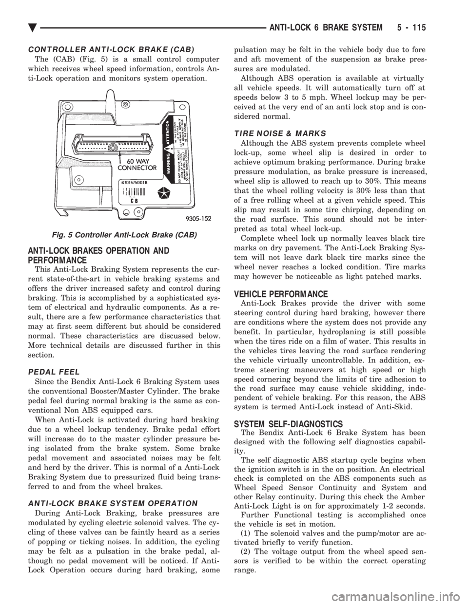
CONTROLLER ANTI-LOCK BRAKE (CAB)
The (CAB) (Fig. 5) is a small control computer
which receives wheel speed information, controls An-
ti-Lock operation and monitors system operation.
ANTI-LOCK BRAKES OPERATION AND
PERFORMANCE
This Anti-Lock Braking System represents the cur-
rent state-of-the-art in vehicle braking systems and
offers the driver increased safety and control during
braking. This is accomplished by a sophisticated sys-
tem of electrical and hydraulic components. As a re-
sult, there are a few performance characteristics that
may at first seem different but should be considered
normal. These characteristics are discussed below.
More technical details are discussed further in this
section.
PEDAL FEEL
Since the Bendix Anti-Lock 6 Braking System uses
the conventional Booster/Master Cylinder. The brake
pedal feel during normal braking is the same as con-
ventional Non ABS equipped cars. When Anti-Lock is activated during hard braking
due to a wheel lockup tendency. Brake pedal effort
will increase do to the master cylinder pressure be-
ing isolated from the brake system. Some brake
pedal movement and associated noises may be felt
and herd by the driver. This is normal of a Anti-Lock
Braking System due to pressurized fluid being trans-
ferred to and from the wheel brakes.
ANTI-LOCK BRAKE SYSTEM OPERATION
During Anti-Lock Braking, brake pressures are
modulated by cycling electric solenoid valves. The cy-
cling of these valves can be faintly heard as a series
of popping or ticking noises. In addition, the cycling
may be felt as a pulsation in the brake pedal, al-
though no pedal movement will be noticed. If Anti-
Lock Operation occurs during hard braking, some pulsation may be felt in the vehicle body due to fore
and aft movement of the suspension as brake pres-
sures are modulated.
Although ABS operation is available at virtually
all vehicle speeds. It will automatically turn off at
speeds below 3 to 5 mph. Wheel lockup may be per-
ceived at the very end of an anti lock stop and is con-
sidered normal.
TIRE NOISE & MARKS
Although the ABS system prevents complete wheel
lock-up, some wheel slip is desired in order to
achieve optimum braking performance. During brake
pressure modulation, as brake pressure is increased,
wheel slip is allowed to reach up to 30%. This means
that the wheel rolling velocity is 30% less than that
of a free rolling wheel at a given vehicle speed. This
slip may result in some tire chirping, depending on
the road surface. This sound should not be inter-
preted as total wheel lock-up. Complete wheel lock up normally leaves black tire
marks on dry pavement. The Anti-Lock Braking Sys-
tem will not leave dark black tire marks since the
wheel never reaches a locked condition. Tire marks
may however be noticeable as light patched marks.
VEHICLE PERFORMANCE
Anti-Lock Brakes provide the driver with some
steering control during hard braking, however there
are conditions where the system does not provide any
benefit. In particular, hydroplaning is still possible
when the tires ride on a film of water. This results in
the vehicles tires leaving the road surface rendering
the vehicle virtually uncontrollable. In addition, ex-
treme steering maneuvers at high speed or high
speed cornering beyond the limits of tire adhesion to
the road surface may cause vehicle skidding, inde-
pendent of vehicle braking. For this reason, the ABS
system is termed Anti-Lock instead of Anti-Skid.
SYSTEM SELF-DIAGNOSTICS
The Bendix Anti-Lock 6 Brake System has been
designed with the following self diagnostics capabil-
ity. The self diagnostic ABS startup cycle begins when
the ignition switch is in the on position. An electrical
check is completed on the ABS components such as
Wheel Speed Sensor Continuity and System and
other Relay continuity. During this check the Amber
Anti-Lock Light is on for approximately 1-2 seconds. Further Functional testing is accomplished once
the vehicle is set in motion. (1) The solenoid valves and the pump/motor are ac-
tivated briefly to verify function. (2) The voltage output from the wheel speed sen-
sors is verified to be within the correct operating
range.
Fig. 5 Controller Anti-Lock Brake (CAB)
Ä ANTI-LOCK 6 BRAKE SYSTEM 5 - 115
Page 301 of 2438
ANTILOCK BRAKES OPERATION AND
PERFORMANCE
The Bendix Antilock 4 Brake System represents
the current state-of-the-art in vehicle brake systems
and offers the driver increased safety and control
during braking. This is accomplished by a sophisti-
cated system of electrical and hydraulic components.
As a result, there are a few performance characteris-
tics that may at first seem different but should be
considered normal. These characteristics are dis-
cussed below. More technical details are discussed
further in this section.
PEDAL FEEL
Since the Bendix Antilock 4 Brake System uses the
vehicle's conventional brake system power booster
and master cylinder. The brake pedal feel during
normal braking is the same as on a conventional
Non ABS equipped vehicle. When the Antilock system becomes activated dur-
ing hard braking due to a wheel lockup tendency.
The brake pedal effort will increase do to the master
cylinder pressure being isolated from the brake sys-
tem. Some brake pedal movement and associated
noises may be felt and heard by the driver. This is
normal operation of the Bendix Antilock 4 Brake
System due to pressurized brake fluid being trans-
ferred to and from the wheel brakes.
ANTILOCK BRAKE SYSTEM OPERATION
During Antilock Brake system operation, brake
pressures are modulated by cycling electric solenoid
valves. The cycling of these valves can be heard as a
series of popping or ticking noises. In addition, the
cycling may be felt as a pulsation in the brake pedal.
If Antilock operation occurs during a hard applica-
tion of the brakes, some pulsation may be felt in the
vehicle body due to fore and aft movement of vehicle
suspension components. Although ABS operation is available at virtually
all vehicle speeds, it will automatically turn off at
speeds below 3 to 5 mph. Wheel lockup may be per-
ceived at the very end of an anti lock stop and is con-
sidered normal.
TIRE NOISE & MARKS
Although the ABS system prevents complete wheel
lock-up, some wheel slip is desired in order to
achieve optimum vehicle braking performance. During brake fluid pressure modulation, as the
brake fluid pressure is increased, wheel slip is al-
lowed to reach up to 30%. This means that wheel
rolling speed is 30% less than that of a free rolling
wheel at a given vehicle speed. This slip may result
in some tire chirping, depending on the road surface.
This sound should not be interpreted as total wheel
lock-up. Complete wheel lock up normally leaves black tire
marks on dry pavement. The Antilock Brake System
will not leave dark black tire marks since the wheel
never reaches a locked condition. Tire marks may
however be noticeable as light patched marks.
VEHICLE PERFORMANCE
Antilock Brakes provide the driver with some
steering control during hard braking, however there
are conditions where the system does not provide any
benefit. In particular, hydroplaning is still possible
when the tires ride on a film of water. This results in
the vehicles tires leaving the road surface rendering
the vehicle virtually uncontrollable. In addition, ex-
treme steering maneuvers at high speed or high
speed cornering beyond the limits of tire adhesion to
the road surface may cause vehicle skidding, inde-
pendent of vehicle braking. For this reason, the ABS
system is termed Antilock instead of Anti-Skid.
SYSTEM SELF-DIAGNOSTICS
The Bendix Antilock 4 Brake System has been de-
signed with the following self diagnostic capabilities. The self diagnostic ABS startup cycle begins when
the ignition switch is turned to the on position. At
this time an electrical check is completed on the ABS
components such as Wheel Speed Sensor Continuity
and System and other Relay continuity. During this
check the Amber Antilock Light is on for approxi-
mately 1-2 seconds. Further Antilock Brake System functional testing
is accomplished once the vehicle is set in motion,
known as drive-off. (1) The solenoid valves and the pump/motor are ac-
tivated briefly to verify function.
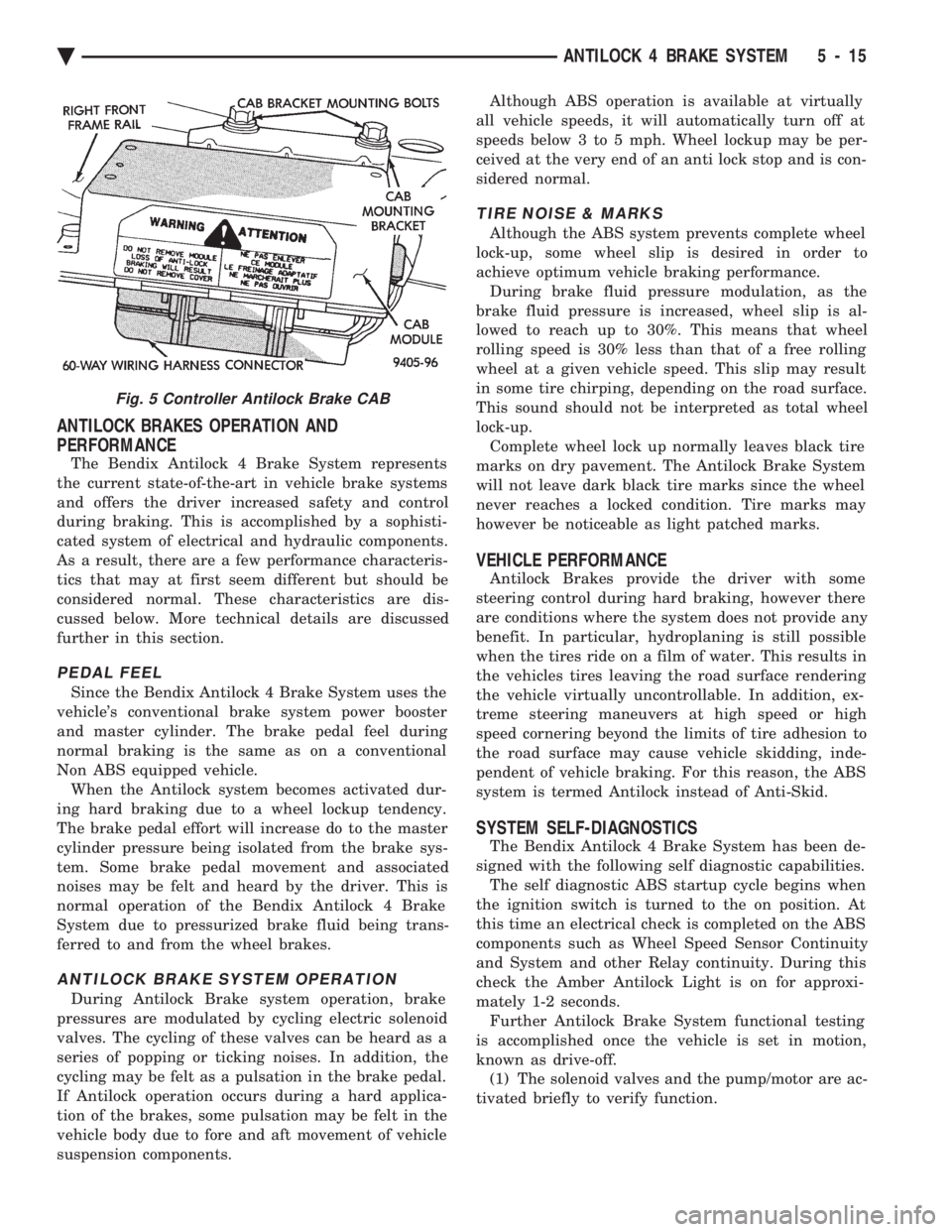
Fig. 5 Controller Antilock Brake CAB
Ä ANTILOCK 4 BRAKE SYSTEM 5 - 15
Page 343 of 2438
COOLING SYSTEM
CONTENTS
page page
ACCESSORY DRIVE BELTS ............... 24
ENGINE BLOCK HEATER ................. 28
GENERAL INFORMATION .................. 1 SERVICE PROCEDURES
.................. 10
SPECIFICATIONS ....................... 29
GENERAL INFORMATION
Throughout this group, references may be made to
a particular vehicle by letter or number designation.
A chart showing the breakdown of these designations
is included in the Introduction Section at the front of
this service manual.
COOLING SYSTEM
The cooling system consists of an engine cooling
module, thermostat, coolant, a water pump to circu-
late the coolant. The engine cooling module may con-
sist of a radiator, electric fan motor, shroud, radiator
pressure cap, coolant reserve system, transmission oil
cooler, hoses, clamps, air condition condenser, trans-
mission oil lines and charge air cooler.
² When Engine is cold: Thermostat is closed, cooling
system has no flow through the radiator. The coolant
bypass flows through the engine only. ²
When Engine is warm: Thermostat is open, cooling
system has bypass flow and coolant flow through ra-
diator. Its primary purpose is to maintain engine temper-
ature in a range that will provide satisfactory engine
performance and emission levels under all expected
driving conditions. It also provides hot water (cool-
ant) for heater performance and cooling for auto-
matic transmission oil. It does this by transferring
heat from engine metal to coolant, moving this
heated coolant to the radiator, and then transferring
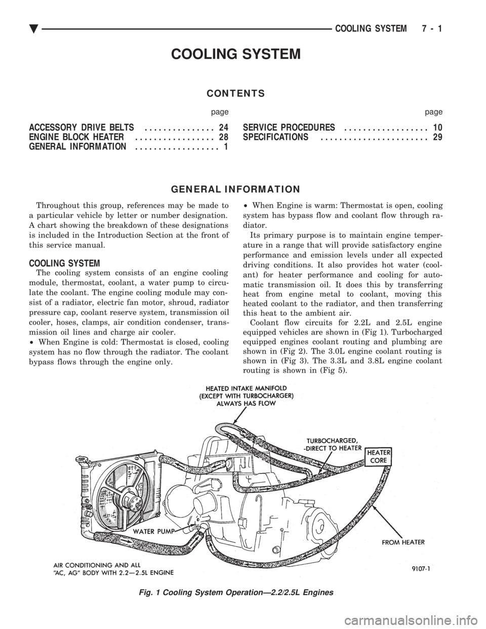
this heat to the ambient air. Coolant flow circuits for 2.2L and 2.5L engine
equipped vehicles are shown in (Fig 1). Turbocharged
equipped engines coolant routing and plumbing are
shown in (Fig 2). The 3.0L engine coolant routing is
shown in (Fig 3). The 3.3L and 3.8L engine coolant
routing is shown in (Fig 5).
Fig. 1 Cooling System OperationÐ2.2/2.5L Engines
Ä COOLING SYSTEM 7 - 1
Page 344 of 2438
TURBOCHARGER COOLANT ROUTING
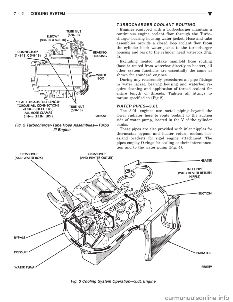
Engines equipped with a Turbocharger maintain a
continuous engine coolant flow through the Turbo-
charger bearing housing water jacket. Hose and tube
assemblies provide a closed loop coolant flow from
the cylinder block water jacket to the turbocharger
housing and back to the cylinder head waterbox (Fig.
2). Excluding heated intake manifold hose routing
(hose is routed from waterbox directly to heater), all
other system functions are essentially the same as
shown for standard engines. During any reassembly procedures all pipe fittings
in water jacket, bearing housing and waterbox re-
quire cleaning and application of thread sealant for
entire length of threads. Tighten all fittings to
torque specified in (Fig 2).
WATER PIPESÐ3.0L
The 3.0L engines use metal piping beyond the
lower radiator hose to route coolant to the suction
side of water pump, located in the V of the cylinder
banks. These pipes are also provided with inlet nipples for
thermostat bypass and heater return coolant hos-
es,and brackets for rigid engine attachment. The
pipes employ O-rings for sealing at their interconnec-
tion and to the water pump (Fig. 4).
Fig. 2 Turbocharger-Tube Hose AssembliesÐTurbo III Engine
Fig. 3 Cooling System OperationÐ3.0L Engine
7 - 2 COOLING SYSTEM Ä
Page 352 of 2438
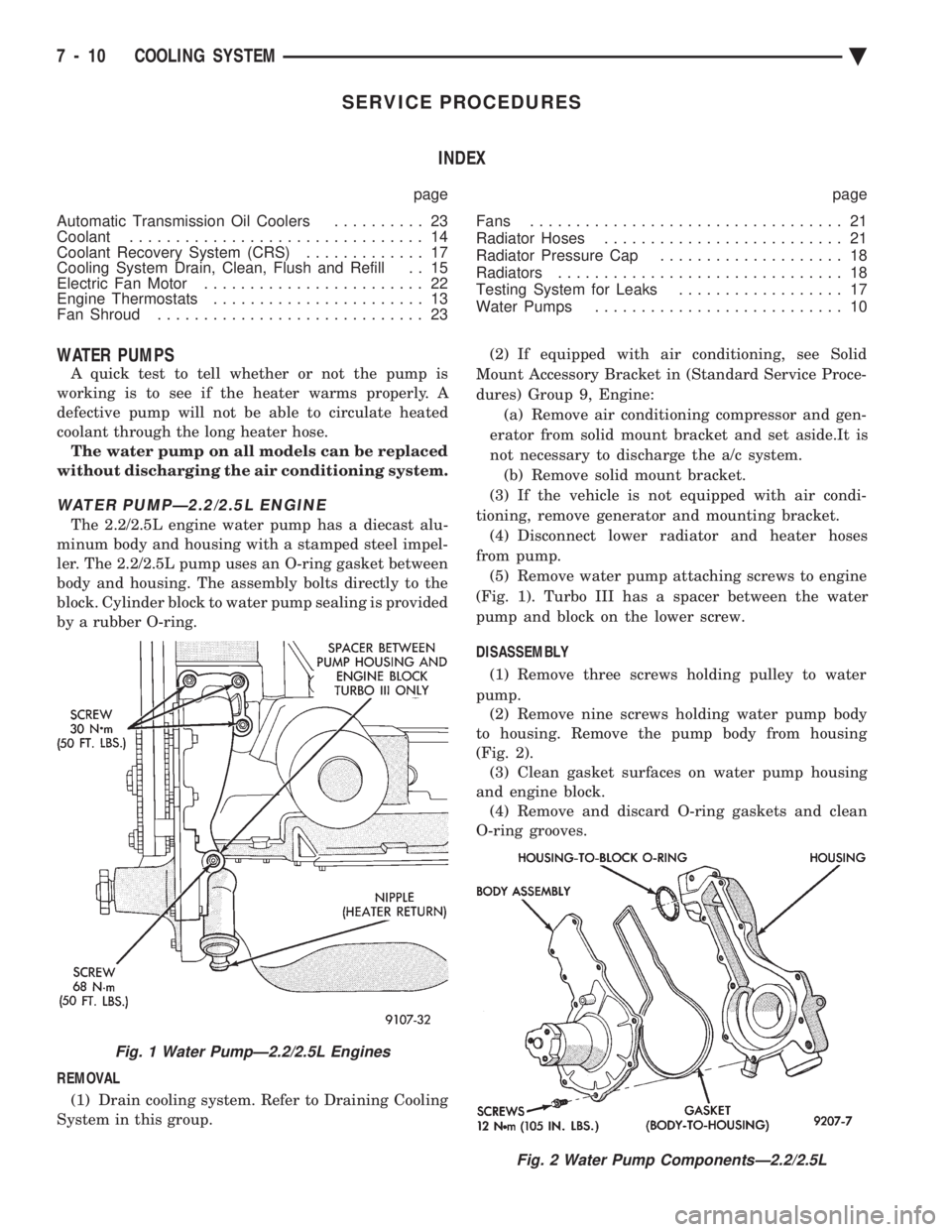
SERVICE PROCEDURES INDEX
page page
Automatic Transmission Oil Coolers .......... 23
Coolant ................................ 14
Coolant Recovery System (CRS) ............. 17
Cooling System Drain, Clean, Flush and Refill . . 15
Electric Fan Motor ........................ 22
Engine Thermostats ....................... 13
Fan Shroud ............................. 23 Fans
.................................. 21
Radiator Hoses .......................... 21
Radiator Pressure Cap .................... 18
Radiators ............................... 18
Testing System for Leaks .................. 17
Water Pumps ........................... 10
WATER PUMPS
A quick test to tell whether or not the pump is
working is to see if the heater warms properly. A
defective pump will not be able to circulate heated
coolant through the long heater hose. The water pump on all models can be replaced
without discharging the air conditioning system.
WATER PUMPÐ2.2/2.5L ENGINE
The 2.2/2.5L engine water pump has a diecast alu-
minum body and housing with a stamped steel impel-
ler. The 2.2/2.5L pump uses an O-ring gasket between
body and housing. The assembly bolts directly to the
block. Cylinder block to water pump sealing is provided
by a rubber O-ring.
REMOVAL (1) Drain cooling system. Refer to Draining Cooling
System in this group. (2) If equipped with air conditioning, see Solid
Mount Accessory Bracket in (Standard Service Proce-
dures) Group 9, Engine: (a) Remove air conditioning compressor and gen-
erator from solid mount bracket and set aside.It is
not necessary to discharge the a/c system. (b) Remove solid mount bracket.
(3) If the vehicle is not equipped with air condi-
tioning, remove generator and mounting bracket. (4) Disconnect lower radiator and heater hoses
from pump. (5) Remove water pump attaching screws to engine
(Fig. 1). Turbo III has a spacer between the water
pump and block on the lower screw.
DISASSEMBLY (1) Remove three screws holding pulley to water
pump. (2) Remove nine screws holding water pump body
to housing. Remove the pump body from housing
(Fig. 2). (3) Clean gasket surfaces on water pump housing
and engine block. (4) Remove and discard O-ring gaskets and clean
O-ring grooves.
Fig. 2 Water Pump ComponentsÐ2.2/2.5L
Fig. 1 Water PumpÐ2.2/2.5L Engines
7 - 10 COOLING SYSTEM Ä