driver seat adjustment CHEVROLET DYNASTY 1993 Service Manual
[x] Cancel search | Manufacturer: CHEVROLET, Model Year: 1993, Model line: DYNASTY, Model: CHEVROLET DYNASTY 1993Pages: 2438, PDF Size: 74.98 MB
Page 156 of 2438
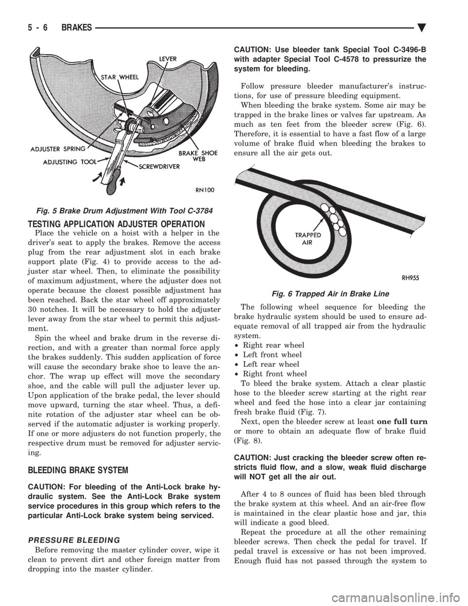
TESTING APPLICATION ADJUSTER OPERATION
Place the vehicle on a hoist with a helper in the
driver's seat to apply the brakes. Remove the access
plug from the rear adjustment slot in each brake
support plate (Fig. 4) to provide access to the ad-
juster star wheel. Then, to eliminate the possibility
of maximum adjustment, where the adjuster does not
operate because the closest possible adjustment has
been reached. Back the star wheel off approximately
30 notches. It will be necessary to hold the adjuster
lever away from the star wheel to permit this adjust-
ment. Spin the wheel and brake drum in the reverse di-
rection, and with a greater than normal force apply
the brakes suddenly. This sudden application of force
will cause the secondary brake shoe to leave the an-
chor. The wrap up effect will move the secondary
shoe, and the cable will pull the adjuster lever up.
Upon application of the brake pedal, the lever should
move upward, turning the star wheel. Thus, a defi-
nite rotation of the adjuster star wheel can be ob-
served if the automatic adjuster is working properly.
If one or more adjusters do not function properly, the
respective drum must be removed for adjuster servic-
ing.
BLEEDING BRAKE SYSTEM
CAUTION: For bleeding of the Anti-Lock brake hy-
draulic system. See the Anti-Lock Brake system
service procedures in this group which refers to the
particular Anti-Lock brake system being serviced.
PRESSURE BLEEDING
Before removing the master cylinder cover, wipe it
clean to prevent dirt and other foreign matter from
dropping into the master cylinder. CAUTION: Use bleeder tank Special Tool C-3496-B
with adapter Special Tool C-4578 to pressurize the
system for bleeding.
Follow pressure bleeder manufacturer's instruc-
tions, for use of pressure bleeding equipment. When bleeding the brake system. Some air may be
trapped in the brake lines or valves far upstream. As
much as ten feet from the bleeder screw (Fig. 6).
Therefore, it is essential to have a fast flow of a large
volume of brake fluid when bleeding the brakes to
ensure all the air gets out.
The following wheel sequence for bleeding the
brake hydraulic system should be used to ensure ad-
equate removal of all trapped air from the hydraulic
system.
² Right rear wheel
² Left front wheel
² Left rear wheel
² Right front wheel
To bleed the brake system. Attach a clear plastic
hose to the bleeder screw starting at the right rear
wheel and feed the hose into a clear jar containing
fresh brake fluid (Fig. 7). Next, open the bleeder screw at least one full turn
or more to obtain an adequate flow of brake fluid
(Fig. 8).
CAUTION: Just cracking the bleeder screw often re-
stricts fluid flow, and a slow, weak fluid discharge
will NOT get all the air out.
After 4 to 8 ounces of fluid has been bled through
the brake system at this wheel. And an air-free flow
is maintained in the clear plastic hose and jar, this
will indicate a good bleed. Repeat the procedure at all the other remaining
bleeder screws. Then check the pedal for travel. If
pedal travel is excessive or has not been improved.
Enough fluid has not passed through the system to
Fig. 5 Brake Drum Adjustment With Tool C-3784
Fig. 6 Trapped Air in Brake Line
5 - 6 BRAKES Ä
Page 1955 of 2438
INTERLOCK SYSTEM ADJUSTMENT
If ignition switch is binding, operating effort high or
can not be turned to the LOCK position, with shifter locked
in PARK, adjustment of Interlock System may be
required. To adjust Interlock System, follow procedure
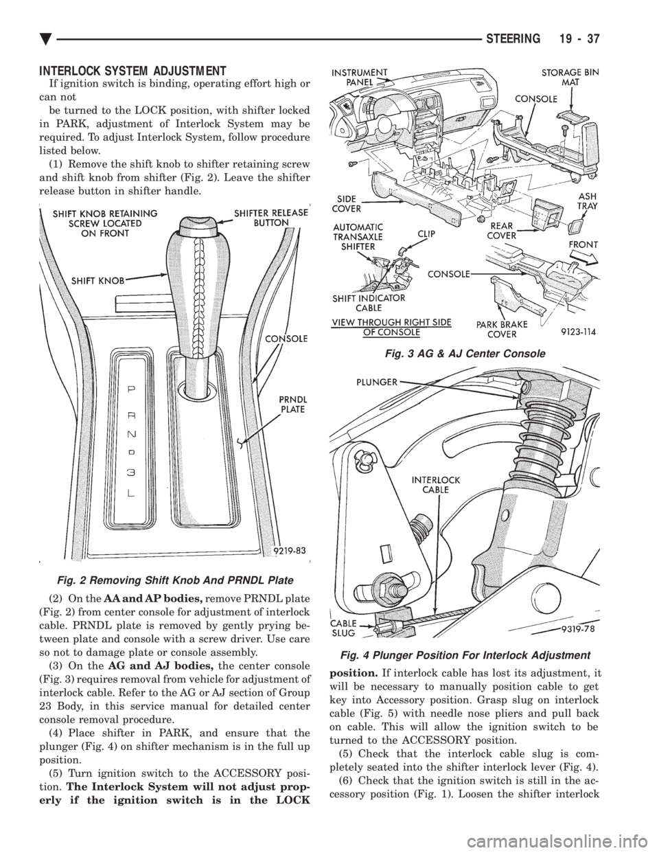
listed below. (1) Remove the shift knob to shifter retaining screw
and shift knob from shifter (Fig. 2). Leave the shifter
release button in shifter handle.
(2) On the AA and AP bodies, remove PRNDL plate
(Fig. 2) from center console for adjustment of interlock
cable. PRNDL plate is removed by gently prying be-
tween plate and console with a screw driver. Use care
so not to damage plate or console assembly. (3) On the AG and AJ bodies, the center console
(Fig. 3) requires removal from vehicle for adjustment of
interlock cable. Refer to the AG or AJ section of Group
23 Body, in this service manual for detailed center
console removal procedure. (4) Place shifter in PARK, and ensure that the
plunger (Fig. 4) on shifter mechanism is in the full up
position. (5) Turn ignition switch to the ACCESSORY posi-
tion. The Interlock System will not adjust prop-
erly if the ignition switch is in the LOCK position.
If interlock cable has lost its adjustment, it
will be necessary to manually position cable to get
key into Accessory position. Grasp slug on interlock
cable (Fig. 5) with needle nose pliers and pull back
on cable. This will allow the ignition switch to be
turned to the ACCESSORY position. (5) Check that the interlock cable slug is com-
pletely seated into the shifter interlock lever (Fig. 4). (6) Check that the ignition switch is still in the ac-
cessory position (Fig. 1). Loosen the shifter interlock
Fig. 3 AG & AJ Center Console
Fig. 4 Plunger Position For Interlock Adjustment
Fig. 2 Removing Shift Knob And PRNDL Plate
Ä STEERING 19 - 37
Page 1962 of 2438
A-568 HEAVYÐDUTY MANUAL TRANSAXLE
The greater torque of the high output turbo engines
require a stronger transmission. It includes a die-cast
aluminum case and a stronger, coarse-pitch gear set. It
has five forward speed ratios and reverse. Gear ratios
are as follows: 1stÐ3.31, 2ndÐ1.89, 3rdÐ1.28,
4thÐ0.94, 5thÐ0.71, ReverseÐ3.14. Final drive ratio
of 3.85 was selected for maximum performance. All
forward gears are synchronized. To reduce wear, this transaxle, in common with other
manual transaxles, uses SAE 5W-30 engine oil as the
lubricant.
IDENTIFICATION
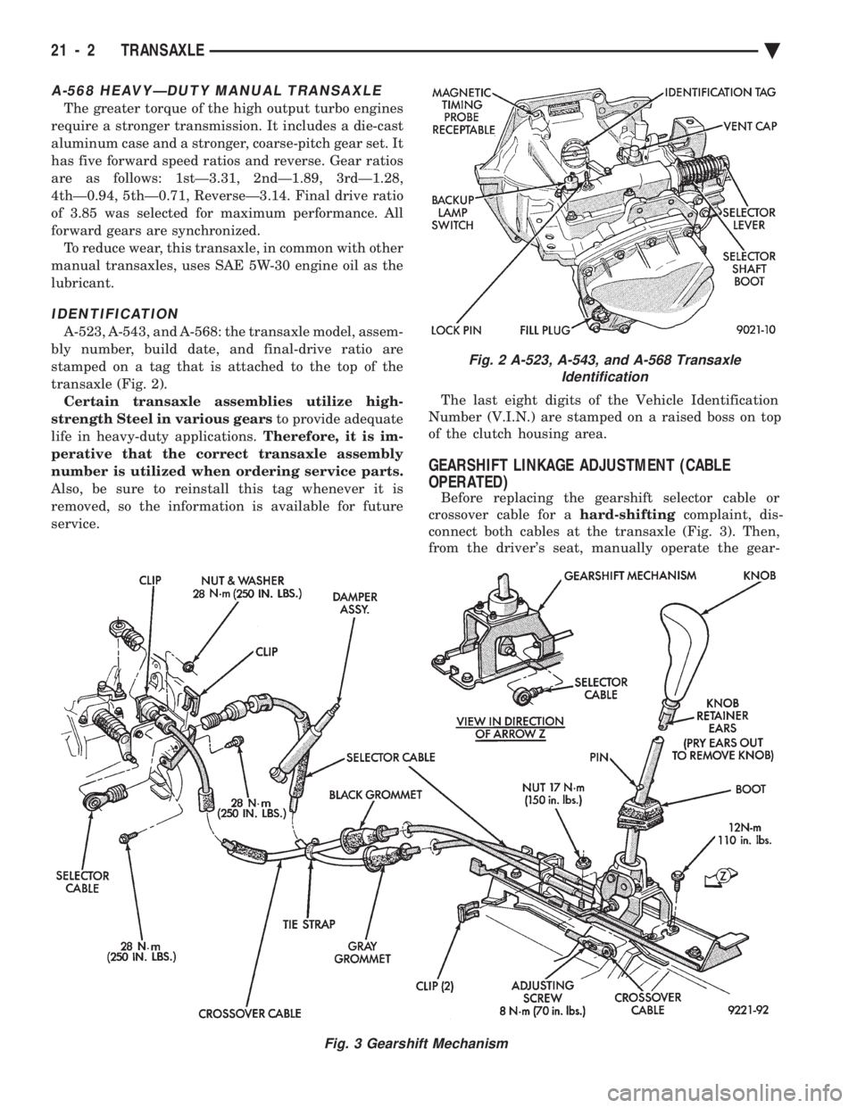
A-523, A-543, and A-568: the transaxle model, assem-
bly number, build date, and final-drive ratio are
stamped on a tag that is attached to the top of the
transaxle (Fig. 2). Certain transaxle assemblies utilize high-
strength Steel in various gears to provide adequate
life in heavy-duty applications. Therefore, it is im-
perative that the correct transaxle assembly
number is utilized when ordering service parts.
Also, be sure to reinstall this tag whenever it is
removed, so the information is available for future
service. The last eight digits of the Vehicle Identification
Number (V.I.N.) are stamped on a raised boss on top
of the clutch housing area.
GEARSHIFT LINKAGE ADJUSTMENT (CABLE
OPERATED)
Before replacing the gearshift selector cable or
crossover cable for a hard-shiftingcomplaint, dis-
connect both cables at the transaxle (Fig. 3). Then,
from the driver's seat, manually operate the gear-
Fig. 2 A-523, A-543, and A-568 Transaxle Identification
Fig. 3 Gearshift Mechanism
21 - 2 TRANSAXLE Ä
Page 2163 of 2438
(2) position wind deflector so 19 mm (0.75 in.)
above top surface of roof panel and 1 mm (0.040 in.)
rearward of roof panel forward edge. (3) Secure wind deflector to sunroof unit.
GLASS PANEL
GLASS PANEL REMOVAL
(1) Remove wind deflector mechanism covers (Fig.
1). (2) Position glass to vent position.
(3) Position sunshade full rearward.
(4) Loosen nuts holding glass panel to side adjust-
ment brackets. (5) Slide glass panel rearward 12 mm (0.5 in.) and
separate glass from sunroof unit.
GLASS PANEL INSTALLATION
(1) Position glass panel in opening with logo rear-
ward and slide panel forward 12 mm (0.5 in.). (2) Verify that attaching nuts are below top sur-
face of glass adjustment brackets. (3) Close sunroof to center glass panel in roof open-
ing. (4) Tighten center screws to hold adjustment.
(5) Open glass to vent position and tighten nuts to
8N Im (70.8 in-lbs.).
(6) Close glass and check alignment.
(7) Install the mechanism covers.
(8) Adjust wind deflector, if necessary.
ADJUSTMENT BRACKET
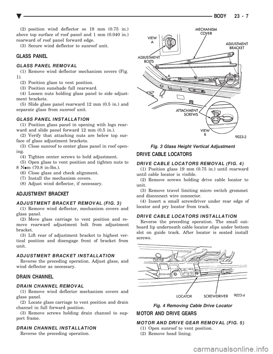
ADJUSTMENT BRACKET REMOVAL (FIG. 3)
(1) Remove wind deflector, mechanism covers and
glass panel. (2) Move glass carriage to vent position and re-
move rearward adjustment bolt from adjustment
bracket. (3) Lift rear of adjustment bracket to highest ver-
tical position and disengage front of bracket from
unit.
ADJUSTMENT BRACKET INSTALLATION
Reverse the preceding operation. Adjust glass, and
wind deflector as necessary.
DRAIN CHANNEL
DRAIN CHANNEL REMOVAL
(1) Remove wind deflector mechanism covers and
glass panel. (2) Locate glass carriage to vent position and drain
channel in full forward position. (3) Remove screws holding drain channel to sup-
port frame.
DRAIN CHANNEL INSTALLATION
Reverse the preceding operation.
DRIVE CABLE LOCATORS
DRIVE CABLE LOCATORS REMOVAL (FIG. 4)
(1) Position glass 19 mm (0.75 in.) until rearward
until cable locator is visible. (2) Remove screws holding drive cable locator to
unit. (3) Remove travel limiting micro switch grommet
and disconnect wire connector. (4) Insert a small screwdriver under rear edge of
locator and pry locator from track.
DRIVE CABLE LOCATORS INSTALLATION
Reverse the preceding operation. The small out-
board lip underneath cable locator slips under bottom
slot on guide track. After locator is seated install
screws.
MOTOR AND DRIVE GEARS
MOTOR AND DRIVE GEAR REMOVAL (FIG. 5)
(1) Open sunroof to vent position.
(2) Remove head lining.
Fig. 3 Glass Height Vertical Adjustment
Fig. 4 Removing Cable Drive Locator
Ä BODY 23 - 7
Page 2242 of 2438
AJ/27-VEHICLE CONVERTIBLE BODY COMPONENT SERVICE INDEX
page page
Adjustment Procedures .................... 92
Folding Top Cover ....................... 90
Folding Top Headlining .................... 87
Folding Top Storage Sling Well .............. 87
Hydraulic Cylinder ........................ 95
Hydraulic Cylinder Line Seals ............... 95
Hydraulic Pump Assembly .................. 95
Hydraulic Pump Line Seals ................. 95 Hydraulic System Tests
.................... 95
Hydraulic Systems ........................ 95
Quarter Window ......................... 87
Rear Seat Back .......................... 86
Rear Seat Belt Retractors .................. 86
Rear Seat Cushion ....................... 86
Rear Window and Zipper ................... 88
Rear WindowÐWithout Zipper ............... 88
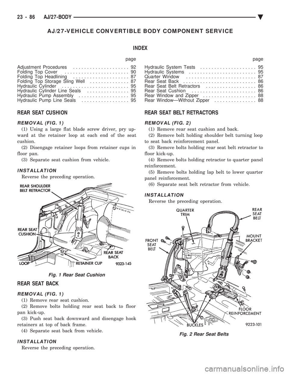
REAR SEAT CUSHION
REMOVAL (FIG. 1)
(1) Using a large flat blade screw driver, pry up-
ward at the retainer loop at each end of the seat
cushion. (2) Disengage retainer loops from retainer cups in
floor pan. (3) Separate seat cushion from vehicle.
INSTALLATION
Reverse the preceding operation.
REAR SEAT BACK
REMOVAL (FIG. 1)
(1) Remove rear seat cushion.
(2) Remove bolts holding rear seat back to floor
pan kick-up. (3) Push seat back downward and disengage hook
retainers at top of back frame. (4) Separate seat back from vehicle.
INSTALLATION
Reverse the preceding operation.
REAR SEAT BELT RETRACTORS
REMOVAL (FIG. 2)
(1) Remove rear seat cushion and back.
(2) Remove bolt holding shoulder belt turning loop
to seat back reinforcement panel. (3) Remove bolts holding rear seat belt retractor to
floor kick-up. (4) Remove bolts holding retractor to quarter panel
reinforcement. (5) Remove bolts holding lap belt to lower quarter
panel reinforcement. (6) Separate seat belt retractor from vehicle.
INSTALLATION
Reverse the preceding operation.
Fig. 1 Rear Seat Cushion
Fig. 2 Rear Seat Belts
23 - 86 AJ/27-BODY Ä