ground clearance CHEVROLET DYNASTY 1993 Service Manual
[x] Cancel search | Manufacturer: CHEVROLET, Model Year: 1993, Model line: DYNASTY, Model: CHEVROLET DYNASTY 1993Pages: 2438, PDF Size: 74.98 MB
Page 43 of 2438

TOWING RECOMMENDATIONS
RECOMMENDED TOWING EQUIPMENT
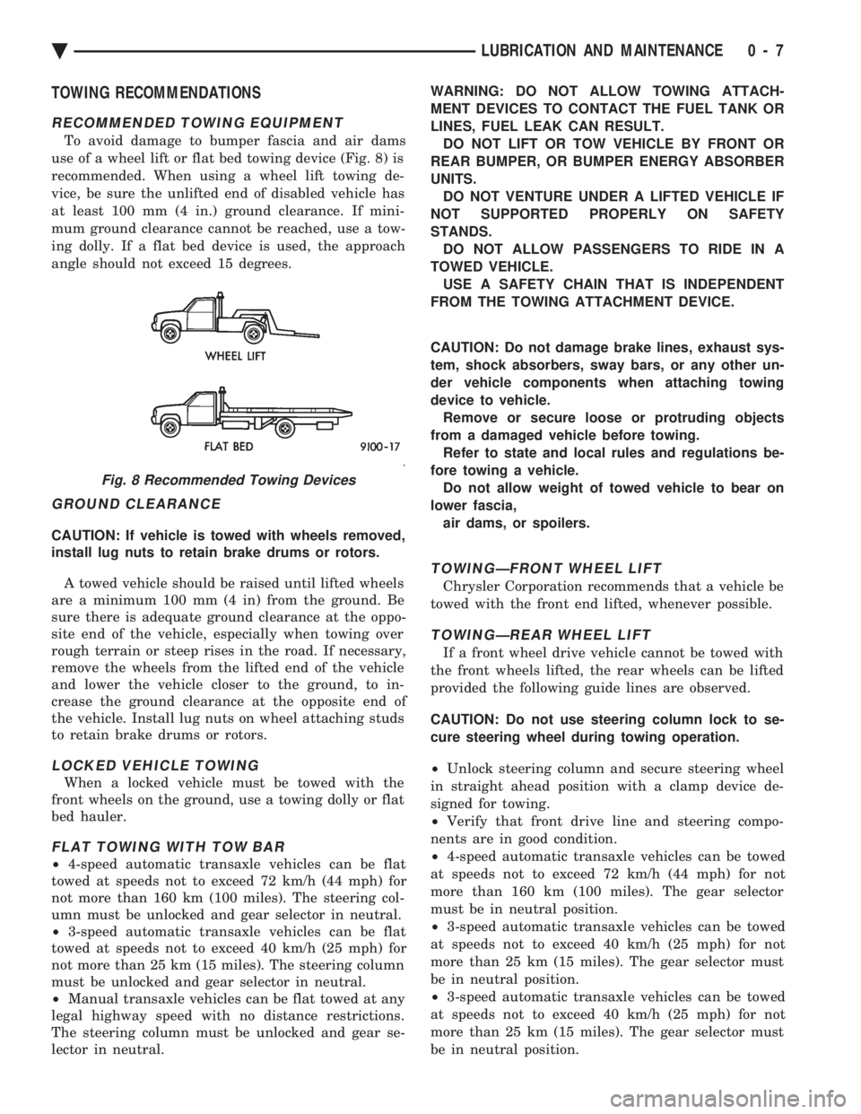
To avoid damage to bumper fascia and air dams
use of a wheel lift or flat bed towing device (Fig. 8) is
recommended. When using a wheel lift towing de-
vice, be sure the unlifted end of disabled vehicle has
at least 100 mm (4 in.) ground clearance. If mini-
mum ground clearance cannot be reached, use a tow-
ing dolly. If a flat bed device is used, the approach
angle should not exceed 15 degrees.
GROUND CLEARANCE
CAUTION: If vehicle is towed with wheels removed,
install lug nuts to retain brake drums or rotors.
A towed vehicle should be raised until lifted wheels
are a minimum 100 mm (4 in) from the ground. Be
sure there is adequate ground clearance at the oppo-
site end of the vehicle, especially when towing over
rough terrain or steep rises in the road. If necessary,
remove the wheels from the lifted end of the vehicle
and lower the vehicle closer to the ground, to in-
crease the ground clearance at the opposite end of
the vehicle. Install lug nuts on wheel attaching studs
to retain brake drums or rotors.
LOCKED VEHICLE TOWING
When a locked vehicle must be towed with the
front wheels on the ground, use a towing dolly or flat
bed hauler.
FLAT TOWING WITH TOW BAR
² 4-speed automatic transaxle vehicles can be flat
towed at speeds not to exceed 72 km/h (44 mph) for
not more than 160 km (100 miles). The steering col-
umn must be unlocked and gear selector in neutral.
² 3-speed automatic transaxle vehicles can be flat
towed at speeds not to exceed 40 km/h (25 mph) for
not more than 25 km (15 miles). The steering column
must be unlocked and gear selector in neutral.
² Manual transaxle vehicles can be flat towed at any
legal highway speed with no distance restrictions.
The steering column must be unlocked and gear se-
lector in neutral. WARNING: DO NOT ALLOW TOWING ATTACH-
MENT DEVICES TO CONTACT THE FUEL TANK OR
LINES, FUEL LEAK CAN RESULT. DO NOT LIFT OR TOW VEHICLE BY FRONT OR
REAR BUMPER, OR BUMPER ENERGY ABSORBER
UNITS. DO NOT VENTURE UNDER A LIFTED VEHICLE IF
NOT SUPPORTED PROPERLY ON SAFETY
STANDS. DO NOT ALLOW PASSENGERS TO RIDE IN A
TOWED VEHICLE. USE A SAFETY CHAIN THAT IS INDEPENDENT
FROM THE TOWING ATTACHMENT DEVICE.
CAUTION: Do not damage brake lines, exhaust sys-
tem, shock absorbers, sway bars, or any other un-
der vehicle components when attaching towing
device to vehicle. Remove or secure loose or protruding objects
from a damaged vehicle before towing. Refer to state and local rules and regulations be-
fore towing a vehicle. Do not allow weight of towed vehicle to bear on
lower fascia, air dams, or spoilers.
TOWINGÐFRONT WHEEL LIFT
Chrysler Corporation recommends that a vehicle be
towed with the front end lifted, whenever possible.
TOWINGÐREAR WHEEL LIFT
If a front wheel drive vehicle cannot be towed with
the front wheels lifted, the rear wheels can be lifted
provided the following guide lines are observed.
CAUTION: Do not use steering column lock to se-
cure steering wheel during towing operation.
² Unlock steering column and secure steering wheel
in straight ahead position with a clamp device de-
signed for towing.
² Verify that front drive line and steering compo-
nents are in good condition.
² 4-speed automatic transaxle vehicles can be towed
at speeds not to exceed 72 km/h (44 mph) for not
more than 160 km (100 miles). The gear selector
must be in neutral position.
² 3-speed automatic transaxle vehicles can be towed
at speeds not to exceed 40 km/h (25 mph) for not
more than 25 km (15 miles). The gear selector must
be in neutral position.
² 3-speed automatic transaxle vehicles can be towed
at speeds not to exceed 40 km/h (25 mph) for not
more than 25 km (15 miles). The gear selector must
be in neutral position.
Fig. 8 Recommended Towing Devices
Ä LUBRICATION AND MAINTENANCE 0 - 7
Page 147 of 2438

REAR (STUB) AXLE ALIGNMENT ALL MODELS INDEX
page page
General Information ....................... 89 Rear Wheel Alignment..................... 89
GENERAL INFORMATION
Because front wheel drive vehicles are equipped with
rear suspension incorporating stub axles (or wheel
spindles). It is possible to align both the camber and toe
of the rear wheels.
REAR WHEEL ALIGNMENT
Alignment adjustment if required. Is made by adding
0.010 inch shims (from the service package kit) be-
tween the spindle mounting surface and axle mounting
plate. Each shim equals wheel change by .3É as shown
(for all car lines) in (Figs. 3 to 6). If rear wheel alignment is required, place vehicle on
alignment rack and check alignment specifications.
When recording rear toe-in (vehicle backed onto
alignment rack) REMEMBER to reverse sign
convention; a total toe-in on direct reading
charts is actually toe-out while driving. Maintain
rear alignment within Chrysler Motors recommenda-
tions, found in Specifications.
INSTALLATION OF REAR ALIGNMENT SHIMS
(1) Block front tires so vehicle will not move.
(2) Release parking brake.
(3) Hoist vehicle so that rear suspension is in full
rebound and tires are off the ground. See Hoisting in
Lubrication and Maintenance, Group 0. (4) Remove wheel and tire assembly.
(5) Pry off grease cap.
(6) Remove cotter pin and castle lock.
(7) Remove adjusting nut.
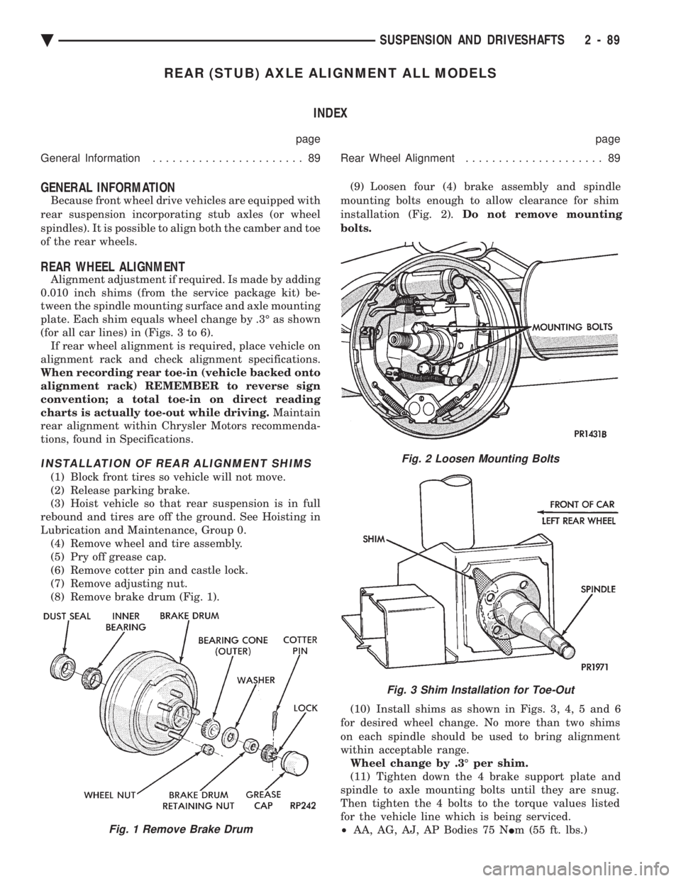
(8) Remove brake drum (Fig. 1). (9) Loosen four (4) brake assembly and spindle
mounting bolts enough to allow clearance for shim
installation (Fig. 2). Do not remove mounting
bolts.
(10) Install shims as shown in Figs. 3, 4, 5 and 6
for desired wheel change. No more than two shims
on each spindle should be used to bring alignment
within acceptable range. Wheel change by .3É per shim.
(11) Tighten down the 4 brake support plate and
spindle to axle mounting bolts until they are snug.
Then tighten the 4 bolts to the torque values listed
for the vehicle line which is being serviced.
² AA, AG, AJ, AP Bodies 75 N Im (55 ft. lbs.)
Fig. 2 Loosen Mounting Bolts
Fig. 3 Shim Installation for Toe-Out
Fig. 1 Remove Brake Drum
Ä SUSPENSION AND DRIVESHAFTS 2 - 89
Page 1596 of 2438

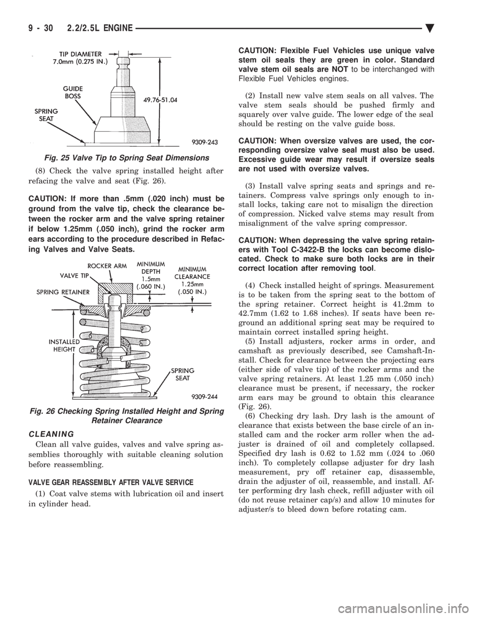
(8) Check the valve spring installed height after
refacing the valve and seat (Fig. 26).
CAUTION: If more than .5mm (.020 inch) must be
ground from the valve tip, check the clearance be-
tween the rocker arm and the valve spring retainer
if below 1.25mm (.050 inch), grind the rocker arm
ears according to the procedure described in Refac-
ing Valves and Valve Seats.
CLEANING
Clean all valve guides, valves and valve spring as-
semblies thoroughly with suitable cleaning solution
before reassembling.
VALVE GEAR REASSEMBLY AFTER VALVE SERVICE (1) Coat valve stems with lubrication oil and insert
in cylinder head. CAUTION: Flexible Fuel Vehicles use unique valve
stem oil seals they are green in color. Standard
valve stem oil seals are NOT to be interchanged with
Flexible Fuel Vehicles engines.
(2) Install new valve stem seals on all valves. The
valve stem seals should be pushed firmly and
squarely over valve guide. The lower edge of the seal
should be resting on the valve guide boss.
CAUTION: When oversize valves are used, the cor-
responding oversize valve seal must also be used.
Excessive guide wear may result if oversize seals
are not used with oversize valves.
(3) Install valve spring seats and springs and re-
tainers. Compress valve springs only enough to in-
stall locks, taking care not to misalign the direction
of compression. Nicked valve stems may result from
misalignment of the valve spring compressor.
CAUTION: When depressing the valve spring retain-
ers with Tool C-3422-B the locks can become dislo-
cated. Check to make sure both locks are in their
correct location after removing tool .
(4) Check installed height of springs. Measurement
is to be taken from the spring seat to the bottom of
the spring retainer. Correct height is 41.2mm to
42.7mm (1.62 to 1.68 inches). If seats have been re-
ground an additional spring seat may be required to
maintain correct installed spring height. (5) Install adjusters, rocker arms in order, and
camshaft as previously described, see Camshaft-In-
stall. Check for clearance between the projecting ears
(either side of valve tip) of the rocker arms and the
valve spring retainers. At least 1.25 mm (.050 inch)
clearance must be present, if necessary, the rocker
arm ears may be ground to obtain this clearance
(Fig. 26). (6) Checking dry lash. Dry lash is the amount of
clearance that exists between the base circle of an in-
stalled cam and the rocker arm roller when the ad-
juster is drained of oil and completely collapsed.
Specified dry lash is 0.62 to 1.52 mm (.024 to .060
inch). To completely collapse adjuster for dry lash
measurement, pry off retainer cap, disassemble,
drain the adjuster of oil, reassemble, and install. Af-
ter performing dry lash check, refill adjuster with oil
(do not reuse retainer cap/s) and allow 10 minutes for
adjuster/s to bleed down before rotating cam.
Fig. 25 Valve Tip to Spring Seat Dimensions
Fig. 26 Checking Spring Installed Height and Spring Retainer Clearance
9 - 30 2.2/2.5L ENGINE Ä
Page 2079 of 2438

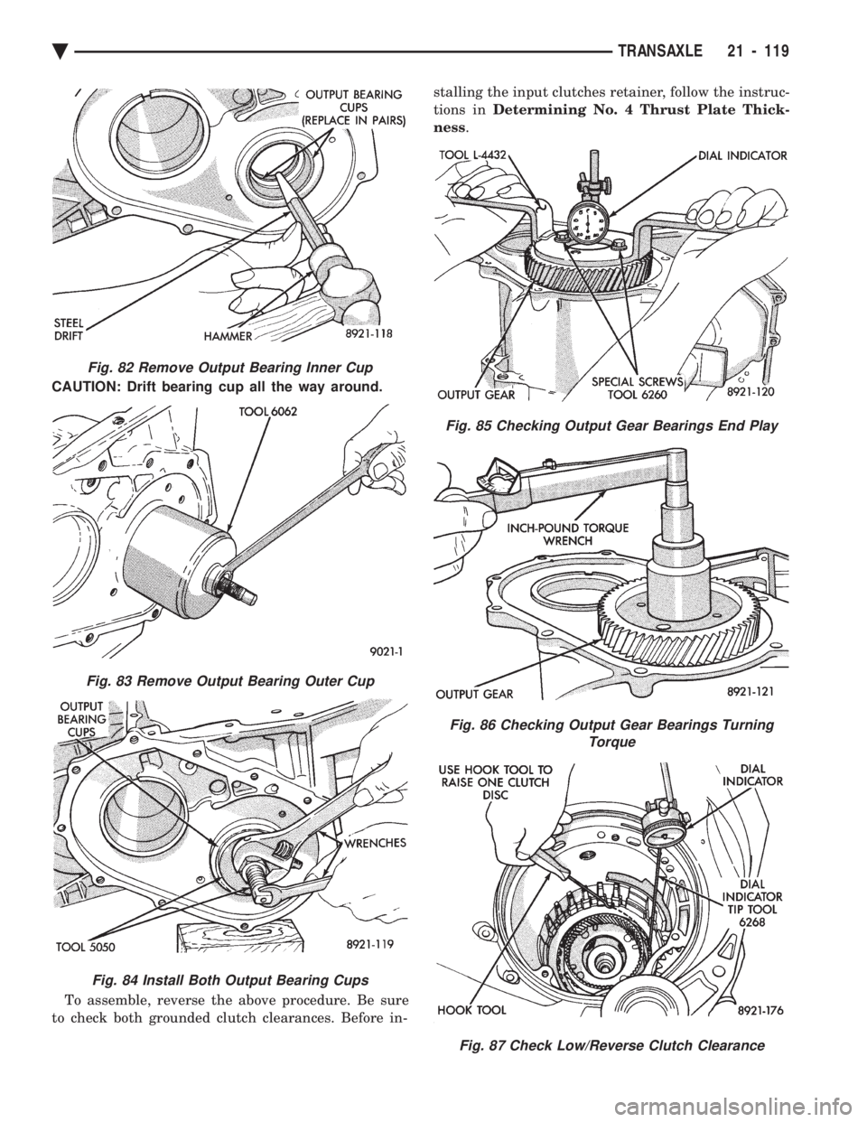
CAUTION: Drift bearing cup all the way around. To assemble, reverse the above procedure. Be sure
to check both grounded clutch clearances. Before in- stalling the input clutches retainer, follow the instruc-
tions in Determining No. 4 Thrust Plate Thick-
ness .
Fig. 82 Remove Output Bearing Inner Cup
Fig. 83 Remove Output Bearing Outer Cup
Fig. 84 Install Both Output Bearing Cups
Fig. 85 Checking Output Gear Bearings End Play
Fig. 86 Checking Output Gear Bearings Turning
Torque
Fig. 87 Check Low/Reverse Clutch Clearance
Ä TRANSAXLE 21 - 119