jack points CHEVROLET DYNASTY 1993 Service Manual
[x] Cancel search | Manufacturer: CHEVROLET, Model Year: 1993, Model line: DYNASTY, Model: CHEVROLET DYNASTY 1993Pages: 2438, PDF Size: 74.98 MB
Page 41 of 2438

(3) On disabled vehicle, place gear selector in park
or neutral and set park brake. Turn off all accesso-
ries. (4) Connect jumper cables to booster battery. RED
clamp to positive terminal (+). BLACK clamp to
negative terminal (-). DO NOT allow clamps at oppo-
site end of cables to touch, electrical arc will result
(Fig. 1). Review all warnings in this procedure. (5) On disabled vehicle, connect RED jumper cable
clamp to positive (+) terminal. Connect BLACK
jumper cable clamp to engine ground as close to the
ground cable attaching point as possible (Fig. 1).
CAUTION: Do not crank starter motor on disabled
vehicle for more than 15 seconds, starter will over-
heat and could fail.
(6) Allow battery in disabled vehicle to charge to
at least 12.4 volts (75% charge) before attempting to
start engine. If engine does not start within 15 sec-
onds, stop cranking engine and allow starter to cool
(15 min.), before cranking again.
DISCONNECT CABLE CLAMPS AS FOLLOWS:
² Disconnect BLACK cable clamp from engine
ground on disabled vehicle.
² When using a Booster vehicle, disconnect BLACK
cable clamp from battery negative terminal. Discon-
nect RED cable clamp from battery positive terminal.
² Disconnect RED cable clamp from battery positive
terminal on disabled vehicle.
HOISTING RECOMMENDATIONS
Refer to Owner's Manual provided with vehicle for
proper emergency jacking procedures.
WARNING: THE HOISTING AND JACK LIFTING
POINTS PROVIDED ARE FOR A COMPLETE VEHI-
CLE. WHEN THE ENGINE OR REAR SUSPENSION IS REMOVED FROM A VEHICLE, THE CENTER OF
GRAVITY IS ALTERED MAKING SOME HOISTING
CONDITIONS UNSTABLE. PROPERLY SUPPORT OR
SECURE VEHICLE TO HOISTING DEVICE WHEN
THESE CONDITIONS EXIST.
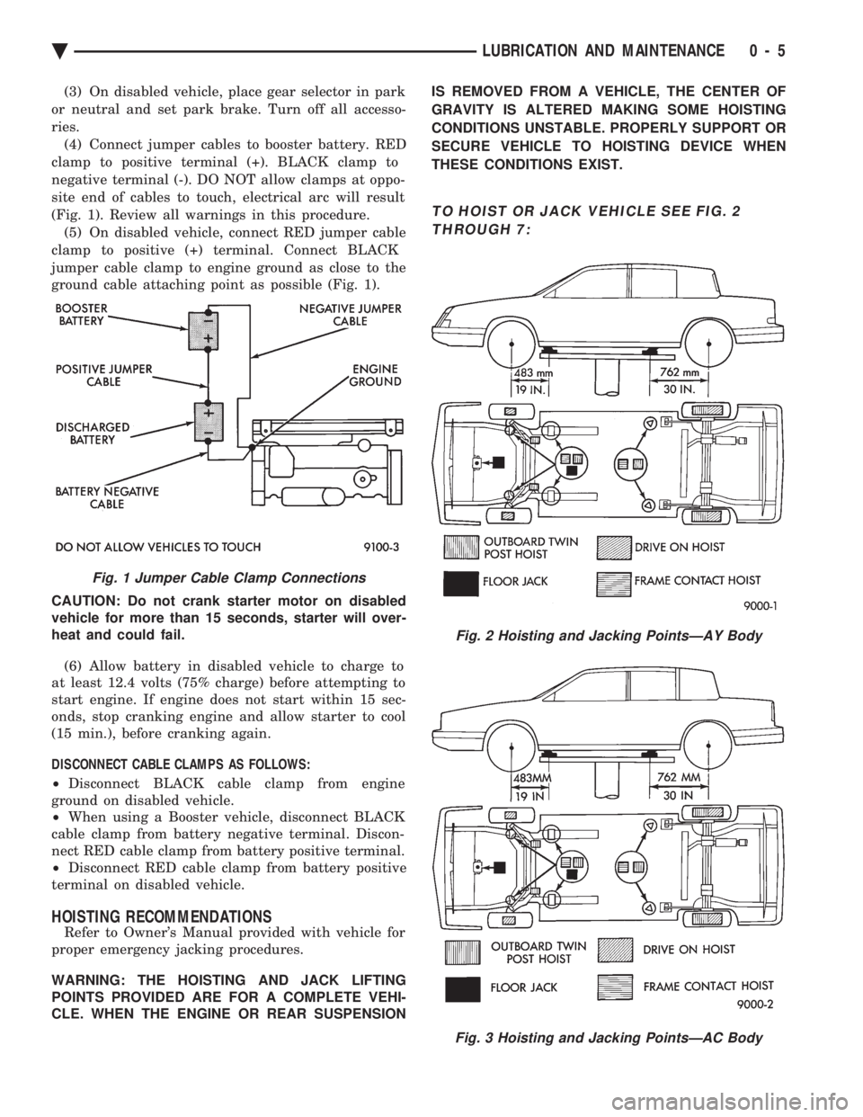
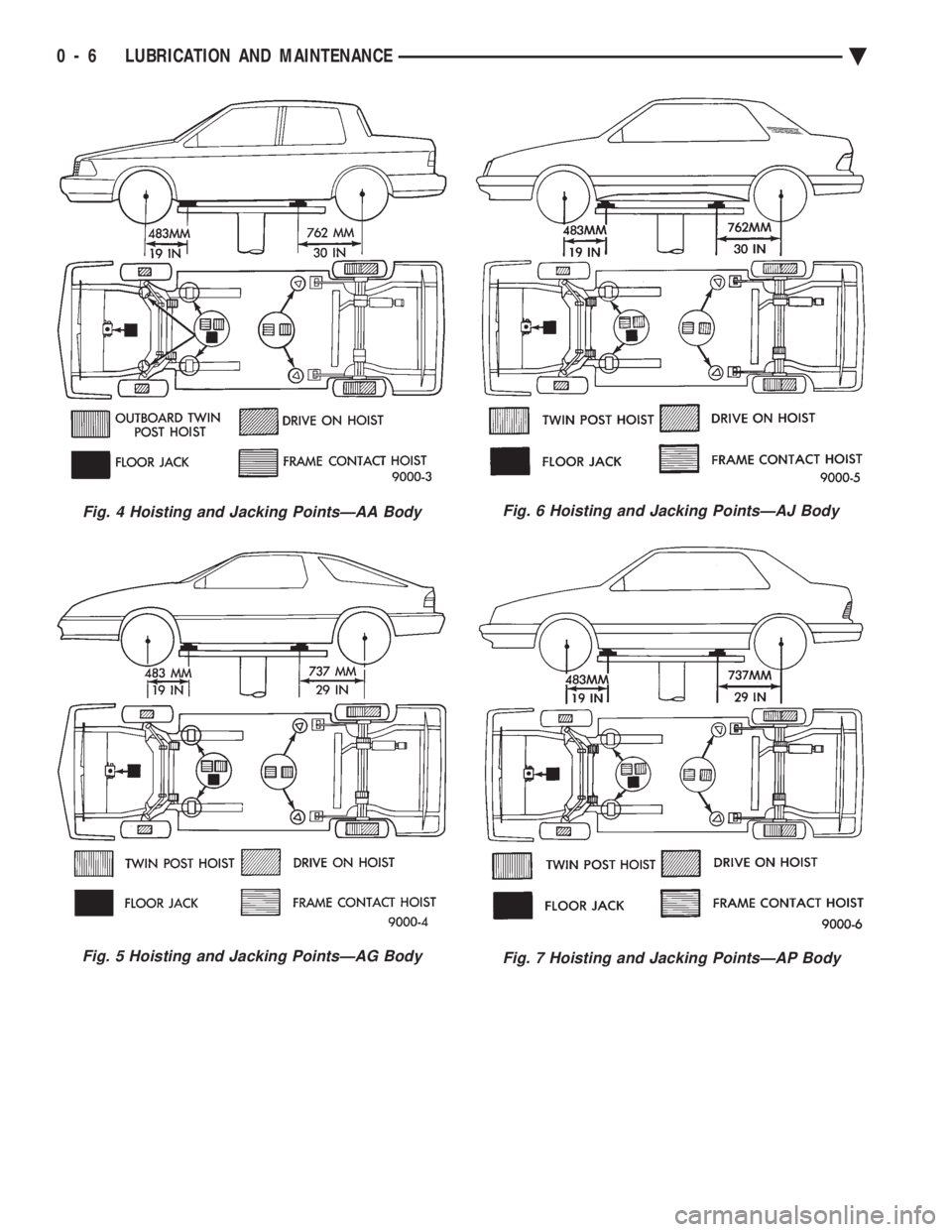
TO HOIST OR JACK VEHICLE SEE FIG. 2 THROUGH 7:
Fig. 1 Jumper Cable Clamp Connections
Fig. 2 Hoisting and Jacking PointsÐAY Body
Fig. 3 Hoisting and Jacking PointsÐAC Body
Ä LUBRICATION AND MAINTENANCE 0 - 5
Page 42 of 2438

Fig. 4 Hoisting and Jacking PointsÐAA Body
Fig. 5 Hoisting and Jacking PointsÐAG Body
Fig. 6 Hoisting and Jacking PointsÐAJ Body
Fig. 7 Hoisting and Jacking PointsÐAP Body
0 - 6 LUBRICATION AND MAINTENANCE Ä
Page 204 of 2438

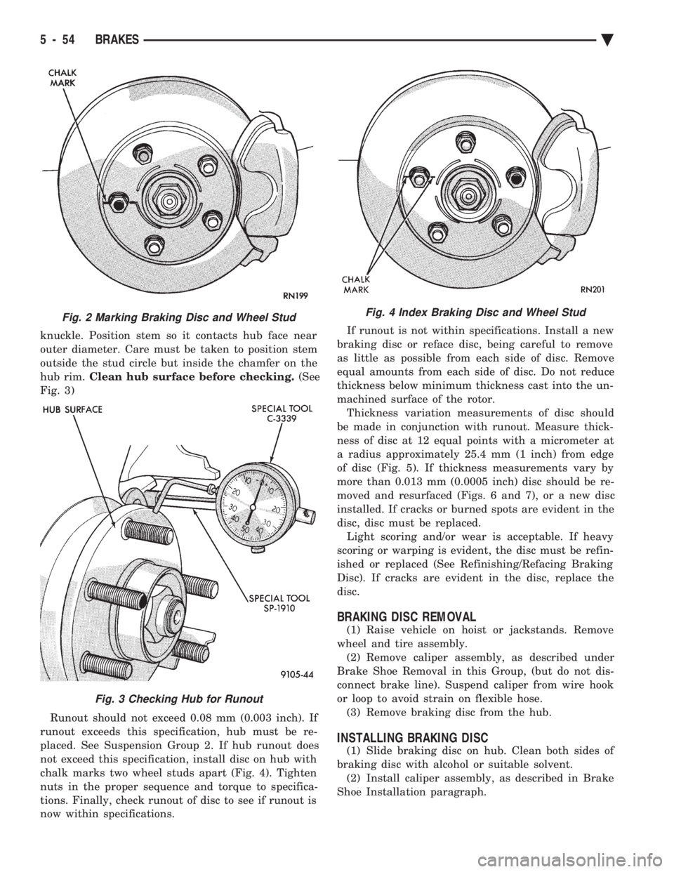
knuckle. Position stem so it contacts hub face near
outer diameter. Care must be taken to position stem
outside the stud circle but inside the chamfer on the
hub rim. Clean hub surface before checking. (See
Fig. 3)
Runout should not exceed 0.08 mm (0.003 inch). If
runout exceeds this specification, hub must be re-
placed. See Suspension Group 2. If hub runout does
not exceed this specification, install disc on hub with
chalk marks two wheel studs apart (Fig. 4). Tighten
nuts in the proper sequence and torque to specifica-
tions. Finally, check runout of disc to see if runout is
now within specifications. If runout is not within specifications. Install a new
braking disc or reface disc, being careful to remove
as little as possible from each side of disc. Remove
equal amounts from each side of disc. Do not reduce
thickness below minimum thickness cast into the un-
machined surface of the rotor. Thickness variation measurements of disc should
be made in conjunction with runout. Measure thick-
ness of disc at 12 equal points with a micrometer at
a radius approximately 25.4 mm (1 inch) from edge
of disc (Fig. 5). If thickness measurements vary by
more than 0.013 mm (0.0005 inch) disc should be re-
moved and resurfaced (Figs. 6 and 7), or a new disc
installed. If cracks or burned spots are evident in the
disc, disc must be replaced. Light scoring and/or wear is acceptable. If heavy
scoring or warping is evident, the disc must be refin-
ished or replaced (See Refinishing/Refacing Braking
Disc). If cracks are evident in the disc, replace the
disc.
BRAKING DISC REMOVAL
(1) Raise vehicle on hoist or jackstands. Remove
wheel and tire assembly. (2) Remove caliper assembly, as described under
Brake Shoe Removal in this Group, (but do not dis-
connect brake line). Suspend caliper from wire hook
or loop to avoid strain on flexible hose. (3) Remove braking disc from the hub.
INSTALLING BRAKING DISC
(1) Slide braking disc on hub. Clean both sides of
braking disc with alcohol or suitable solvent. (2) Install caliper assembly, as described in Brake
Shoe Installation paragraph.
Fig. 2 Marking Braking Disc and Wheel Stud
Fig. 3 Checking Hub for Runout
Fig. 4 Index Braking Disc and Wheel Stud
5 - 54 BRAKES Ä