parking brake CHEVROLET DYNASTY 1993 Service Manual
[x] Cancel search | Manufacturer: CHEVROLET, Model Year: 1993, Model line: DYNASTY, Model: CHEVROLET DYNASTY 1993Pages: 2438, PDF Size: 74.98 MB
Page 31 of 2438
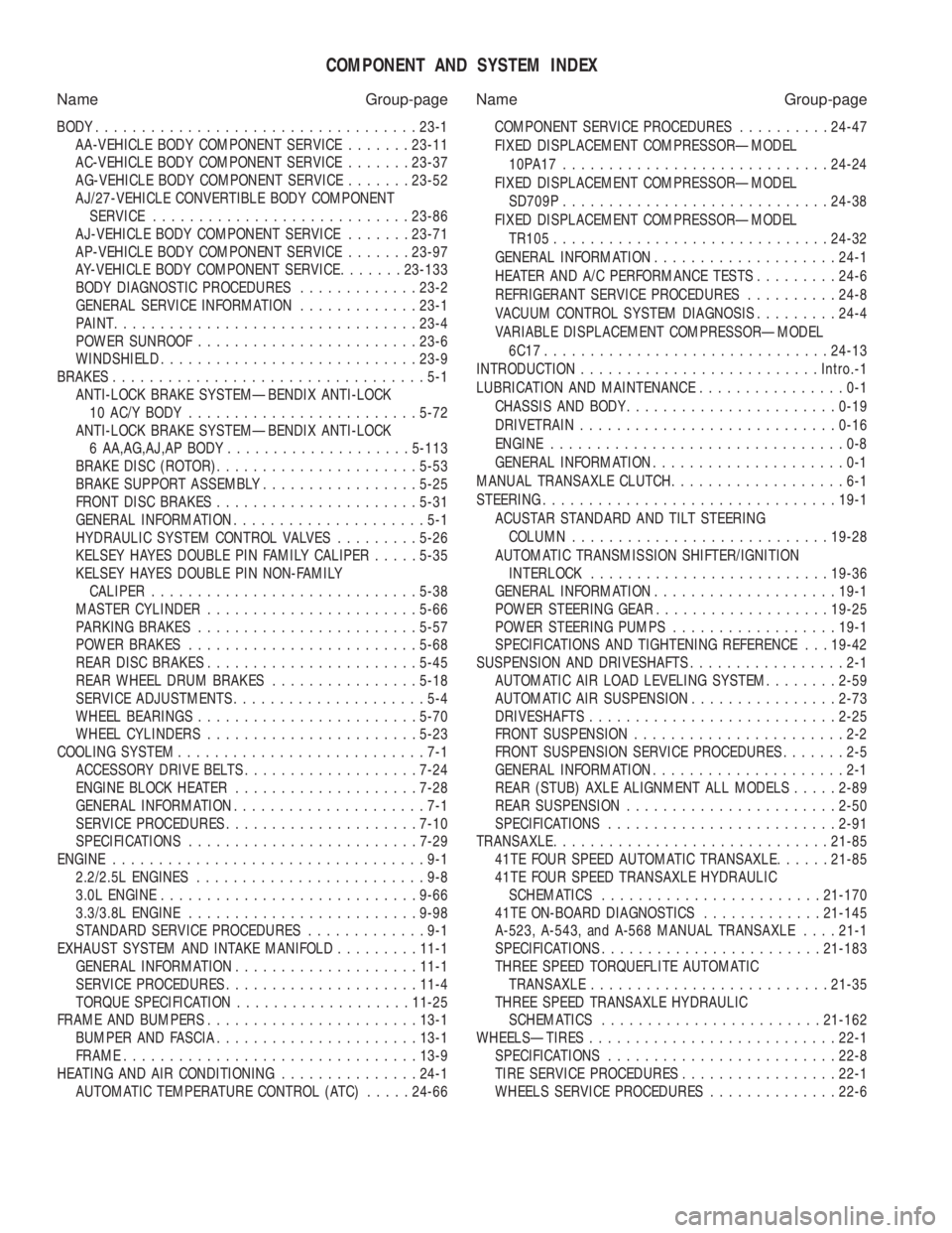
COMPONENT AND SYSTEM INDEX
Name Group-page Name Group-page
BODY ................................... 23-1
AA-VEHICLE BODY COMPONENT SERVICE .......23-11
AC-VEHICLE BODY COMPONENT SERVICE .......23-37
AG-VEHICLE BODY COMPONENT SERVICE .......23-52
AJ/27-VEHICLE CONVERTIBLE BODY COMPONENT SERVICE ............................ 23-86
AJ-VEHICLE BODY COMPONENT SERVICE .......23-71
AP-VEHICLE BODY COMPONENT SERVICE .......23-97
AY-VEHICLE BODY COMPONENT SERVICE .......23-133
BODY DIAGNOSTIC PROCEDURES .............23-2
GENERAL SERVICE INFORMATION .............23-1
PAINT ................................. 23-4
POWER SUNROOF ........................ 23-6
WINDSHIELD ............................ 23-9
BRAKES ..................................5-1
ANTI-LOCK BRAKE SYSTEMÐBENDIX ANTI-LOCK 10 AC/Y BODY ......................... 5-72
ANTI-LOCK BRAKE SYSTEMÐBENDIX ANTI-LOCK 6 AA,AG,AJ,AP BODY .................... 5-113
BRAKE DISC (ROTOR) ...................... 5-53
BRAKE SUPPORT ASSEMBLY .................5-25
FRONT DISC BRAKES ...................... 5-31
GENERAL INFORMATION .....................5-1
HYDRAULIC SYSTEM CONTROL VALVES .........5-26
KELSEY HAYES DOUBLE PIN FAMILY CALIPER .....5-35
KELSEY HAYES DOUBLE PIN NON-FAMILY CALIPER ............................. 5-38
MASTER CYLINDER ....................... 5-66
PARKING BRAKES ........................ 5-57
POWER BRAKES ......................... 5-68
REAR DISC BRAKES ....................... 5-45
REAR WHEEL DRUM BRAKES ................5-18
SERVICE ADJUSTMENTS .....................5-4
WHEEL BEARINGS ........................ 5-70
WHEEL CYLINDERS ....................... 5-23
COOLING SYSTEM ...........................7-1
ACCESSORY DRIVE BELTS ................... 7-24
ENGINE BLOCK HEATER .................... 7-28
GENERAL INFORMATION .....................7-1
SERVICE PROCEDURES ..................... 7-10
SPECIFICATIONS ......................... 7-29
ENGINE ..................................9-1
2.2/2.5L ENGINES .........................9-8
3.0L ENGINE ............................ 9-66
3.3/3.8L ENGINE ......................... 9-98
STANDARD SERVICE PROCEDURES .............9-1
EXHAUST SYSTEM AND INTAKE MANIFOLD .........11-1
GENERAL INFORMATION .................... 11-1
SERVICE PROCEDURES ..................... 11-4
TORQUE SPECIFICATION ................... 11-25
FRAME AND BUMPERS ....................... 13-1
BUMPER AND FASCIA ...................... 13-1
FRAME ................................ 13-9
HEATING AND AIR CONDITIONING ...............24-1
AUTOMATIC TEMPERATURE CONTROL (ATC) .....24-66 COMPONENT SERVICE PROCEDURES
..........24-47
FIXED DISPLACEMENT COMPRESSORÐMODEL 10PA17............................. 24-24
FIXED DISPLACEMENT COMPRESSORÐMODEL SD709P ............................. 24-38
FIXED DISPLACEMENT COMPRESSORÐMODEL TR105 .............................. 24-32
GENERAL INFORMATION .................... 24-1
HEATER AND A/C PERFORMANCE TESTS .........24-6
REFRIGERANT SERVICE PROCEDURES ..........24-8
VACUUM CONTROL SYSTEM DIAGNOSIS .........24-4
VARIABLE DISPLACEMENT COMPRESSORÐMODEL 6C17 ............................... 24-13
INTRODUCTION .......................... Intro.-1
LUBRICATION AND MAINTENANCE ................0-1
CHASSIS AND BODY ....................... 0-19
DRIVETRAIN ............................ 0-16
ENGINE ................................0-8
GENERAL INFORMATION .....................0-1
MANUAL TRANSAXLE CLUTCH ...................6-1
STEERING ................................ 19-1
ACUSTAR STANDARD AND TILT STEERING COLUMN ............................ 19-28
AUTOMATIC TRANSMISSION SHIFTER/IGNITION INTERLOCK .......................... 19-36
GENERAL INFORMATION .................... 19-1
POWER STEERING GEAR ................... 19-25
POWER STEERING PUMPS ..................19-1
SPECIFICATIONS AND TIGHTENING REFERENCE . . . 19-42
SUSPENSION AND DRIVESHAFTS .................2-1
AUTOMATIC AIR LOAD LEVELING SYSTEM ........2-59
AUTOMATIC AIR SUSPENSION ................2-73
DRIVESHAFTS ........................... 2-25
FRONT SUSPENSION .......................2-2
FRONT SUSPENSION SERVICE PROCEDURES .......2-5
GENERAL INFORMATION .....................2-1
REAR (STUB) AXLE ALIGNMENT ALL MODELS .....2-89
REAR SUSPENSION ....................... 2-50
SPECIFICATIONS ......................... 2-91
TRANSAXLE .............................. 21-85
41TE FOUR SPEED AUTOMATIC TRANSAXLE ......21-85
41TE FOUR SPEED TRANSAXLE HYDRAULIC SCHEMATICS ........................ 21-170
41TE ON-BOARD DIAGNOSTICS .............21-145
A-523, A-543, and A-568 MANUAL TRANSAXLE ....21-1
SPECIFICATIONS ........................ 21-183
THREE SPEED TORQUEFLITE AUTOMATIC TRANSAXLE .......................... 21-35
THREE SPEED TRANSAXLE HYDRAULIC SCHEMATICS ........................ 21-162
WHEELSÐTIRES ........................... 22-1
SPECIFICATIONS ......................... 22-8
TIRE SERVICE PROCEDURES .................22-1
WHEELS SERVICE PROCEDURES ..............22-6
Page 116 of 2438
(3) Install washer and nut. Tighten nut to 27-34
N Im (240-300 in. lbs.) torque while rotating brake
drum. Then back off nut to completely release pre-
load. Finger tighten nut. (4) Position nut lock with one pair of slots in-line
with cotter pin hole. Install cotter pin. Clean and in-
stall grease cap. DISC BRAKE ASSEMBLY
(1) Position caliper support and spindle to axle. In-
stall the 4 spindle mounting bolts finger tight. Then
torque the 4 spindle mounting bolts to 75 N Im (55 ft.
lbs.) torque. (2) Install hub and bearings. (3) Install washer and nut. Tighten to 27-34 N
Im
(240-300 in. lbs.) torque while rotating hub. Then
back off nut to completely release preload. Finger
tighten nut. (4) Position nut lock with one pair of slots in-line
with cotter pin hole. Install cotter pin. Clean and in-
stall grease cap. (5) Install braking disc and adapter. Install caliper
assembly (see Rear Disc Brake) in Brakes Section,
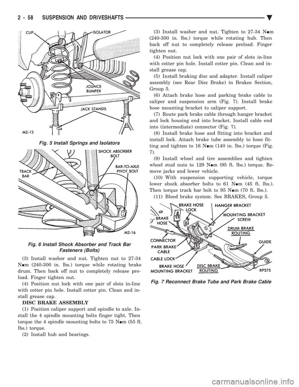
Group 5. (6) Attach brake hose and parking brake cable to
caliper and suspension arm (Fig. 7). Install brake
hose mounting bracket to caliper support. (7) Route park brake cable through hanger bracket
and lock housing end into bracket. Install cable end
into (intermediate) connector (Fig. 7). (8) Install brake hose and fitting into bracket and
install lock. Attach brake tube assembly to hose fit-
ting and tighten to 16 N Im (140 in. lbs.) torque (Fig.
7). (9) Install wheel and tire assemblies and tighten
wheel stud nuts to 129 N Im (95 ft. lbs.) torque. Re-
move jacks and lower vehicle. (10) With suspension supporting vehicle, torque
lower shock absorber bolts to 61 N Im (45 ft. lbs.).
Then torque track bar bolt to 95 N Im (70 ft. lbs.).
(11) Bleed brake system. See BRAKES, Group 5.
Fig. 5 Install Springs and Isolators
Fig. 6 Install Shock Absorber and Track Bar Fasteners (Bolts)
Fig. 7 Reconnect Brake Tube and Park Brake Cable
2 - 58 SUSPENSION AND DRIVESHAFTS Ä
Page 147 of 2438
REAR (STUB) AXLE ALIGNMENT ALL MODELS INDEX
page page
General Information ....................... 89 Rear Wheel Alignment..................... 89
GENERAL INFORMATION
Because front wheel drive vehicles are equipped with
rear suspension incorporating stub axles (or wheel
spindles). It is possible to align both the camber and toe
of the rear wheels.
REAR WHEEL ALIGNMENT
Alignment adjustment if required. Is made by adding
0.010 inch shims (from the service package kit) be-
tween the spindle mounting surface and axle mounting
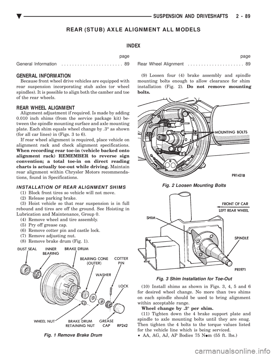
plate. Each shim equals wheel change by .3É as shown
(for all car lines) in (Figs. 3 to 6). If rear wheel alignment is required, place vehicle on
alignment rack and check alignment specifications.
When recording rear toe-in (vehicle backed onto
alignment rack) REMEMBER to reverse sign
convention; a total toe-in on direct reading
charts is actually toe-out while driving. Maintain
rear alignment within Chrysler Motors recommenda-
tions, found in Specifications.
INSTALLATION OF REAR ALIGNMENT SHIMS
(1) Block front tires so vehicle will not move.
(2) Release parking brake.
(3) Hoist vehicle so that rear suspension is in full
rebound and tires are off the ground. See Hoisting in
Lubrication and Maintenance, Group 0. (4) Remove wheel and tire assembly.
(5) Pry off grease cap.
(6) Remove cotter pin and castle lock.
(7) Remove adjusting nut.
(8) Remove brake drum (Fig. 1). (9) Loosen four (4) brake assembly and spindle
mounting bolts enough to allow clearance for shim
installation (Fig. 2). Do not remove mounting
bolts.
(10) Install shims as shown in Figs. 3, 4, 5 and 6
for desired wheel change. No more than two shims
on each spindle should be used to bring alignment
within acceptable range. Wheel change by .3É per shim.
(11) Tighten down the 4 brake support plate and
spindle to axle mounting bolts until they are snug.
Then tighten the 4 bolts to the torque values listed
for the vehicle line which is being serviced.
² AA, AG, AJ, AP Bodies 75 N Im (55 ft. lbs.)
Fig. 2 Loosen Mounting Bolts
Fig. 3 Shim Installation for Toe-Out
Fig. 1 Remove Brake Drum
Ä SUSPENSION AND DRIVESHAFTS 2 - 89
Page 151 of 2438
BRAKES
CONTENTS
page page
ANTI-LOCK BRAKE SYSTEMÐBENDIX ANTI-LOCK 10 AC/Y BODY ............. 72
ANTI-LOCK BRAKE SYSTEMÐBENDIX ANTI-LOCK 6 AA,AG,AJ,AP BODY ....... 113
BRAKE DISC (ROTOR) ................... 53
BRAKE SUPPORT ASSEMBLY ............. 25
FRONT DISC BRAKES ................... 31
GENERAL INFORMATION .................. 1
HYDRAULIC SYSTEM CONTROL VALVES . . . 26
KELSEY HAYES DOUBLE PIN FAMILY CALIPER ............................ 35 KELSEY HAYES DOUBLE PIN NON-FAMILY
CALIPER ............................ 38
MASTER CYLINDER ..................... 66
PARKING BRAKES ...................... 57
POWER BRAKES ....................... 68
REAR DISC BRAKES .................... 45
REAR WHEEL DRUM BRAKES ............ 18
SERVICE ADJUSTMENTS .................. 4
WHEEL BEARINGS ...................... 70
WHEEL CYLINDERS ..................... 23
GENERAL INFORMATION
Throughout this group, references may be made to
a particular vehicle by letter or number designation.
A chart showing the break down of these designa-
tions is included in the Introduction Section at the
front of this service manual. Standard brake equipment consists of:
² Double pin floating caliper disc front brakes.
² Rear automatic adjusting drum brakes.
² Differential valve with a brake warning switch.
² Master cylinder.
² Vacuum power booster.
² Double pin floating caliper rear disc brakes are
available on some models. The Bendix Anti-Lock 10 braking system, uses the
standard power brake system caliper assemblies,
braking discs, pedal assembly, brake lines and hoses.
The unique parts of the Bendix Anti-Lock 10 braking
system consists of the following components. Propor-
tioning valves, wheel speed sensors, tone wheels,
electronic control unit, modulator assembly and hy-
draulic assembly. These components replace the con-
ventional master cylinder and power booster. The
components will be described in detail in the Bendix
Anti-Lock 10 brake section in this group of the ser-
vice manual. The Bendix Anti-Lock 6 braking system, uses the
following standard brake system components. Master
cylinder, power booster, caliper assemblies, braking
discs, pedal assembly, brake lines and hoses. The
unique parts of the Bendix Anti-Lock 6 braking sys-
tem consists of the following components. Modulator
assembly, unique proportioning valves, wheel speed
sensors, tone wheels, and electronic control unit.
These components will be described in detail in the
Bendix Anti-Lock 6 brake section in this group of the
service manual. The front disc brake shoes have semi-metallic lin-
ings. The hydraulic brake system (Fig .123and4)is
diagonally split on both the Non-ABS and ABS brak-
ing system. With the left front and right rear brakes
on one hydraulic system and the right front and left
rear on the other. The Non-ABS and ABS brake system may use dif-
ferent types of brake line fittings and tubing flares.
The Non-ABS brake system uses double wall tubing
flares and fittings at all tubing joint locations. Some
ABS brake systems use both ISO style tubing flares
and double wall tubing flares and corresponding fit-
tings at different joint locations. See (Figs . 2 3 and 4)
for specific joint locations and type of tubing flare. The front disc brakes consist of two different types
of caliper assemblies. A double pin Kelsey-Hayes cal-
iper (family caliper) with a bolt-on adapter attached
to the steering knuckle. Or a double pin Kelsey-
Hayes caliper (non-family caliper) which mounts di-
rectly to rails on the steering knuckle. The non-
family caliper is only used on the AY Body
(Imperials).
CAUTION: Caliper pistons, boots and seals for the
different caliper assemblies used on the front and
rear disc brake assemblies are not interchangeable.
Misusage could result in a complete brake system
failure. Be sure that the parts are replaced with the
correct replacement parts, refer to the parts book
for the type and model year of the vehicle being
worked on.
The master cylinder is anodized, lightweight alu-
minum, with a bore size of 24.0mm, 21.0mm or 7/8
inch.
Ä BRAKES 5 - 1
Page 154 of 2438
SERVICE ADJUSTMENTS INDEX
page page
Adjusting Rear Service Brakes ............... 4
Bleeding Brake System ..................... 6
Brake Hose and Tubing ................... 11
Master Cylinder Fluid Level .................. 4 Stop Lamp Switch Adjustment (All Vehicles)
.... 13
Test for Fluid Contamination ................. 7
Testing Application Adjuster Operation ......... 6
Wheel Stud Nut Tightening .................. 7
MASTER CYLINDER FLUID LEVEL
ALL EXCEPT AC/AY BODY WITH ABS
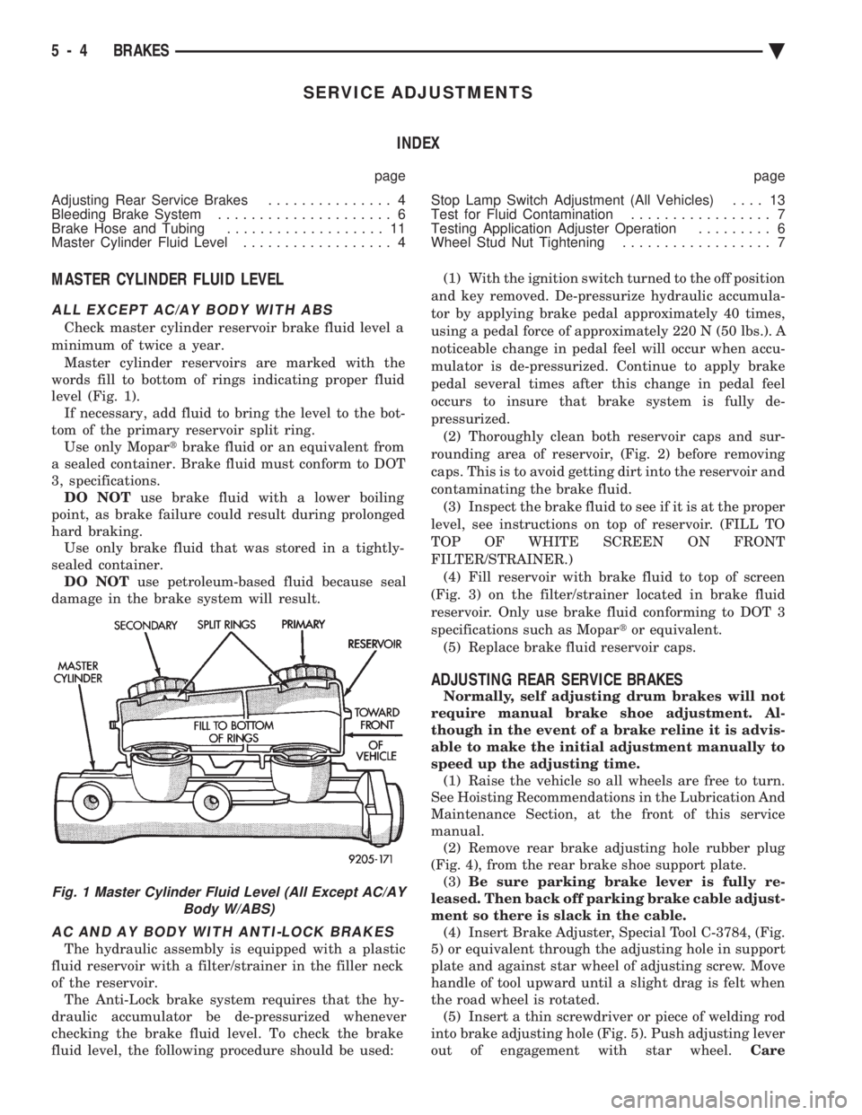
Check master cylinder reservoir brake fluid level a
minimum of twice a year. Master cylinder reservoirs are marked with the
words fill to bottom of rings indicating proper fluid
level (Fig. 1). If necessary, add fluid to bring the level to the bot-
tom of the primary reservoir split ring. Use only Mopar tbrake fluid or an equivalent from
a sealed container. Brake fluid must conform to DOT
3, specifications. DO NOT use brake fluid with a lower boiling
point, as brake failure could result during prolonged
hard braking. Use only brake fluid that was stored in a tightly-
sealed container. DO NOT use petroleum-based fluid because seal
damage in the brake system will result.
AC AND AY BODY WITH ANTI-LOCK BRAKES
The hydraulic assembly is equipped with a plastic
fluid reservoir with a filter/strainer in the filler neck
of the reservoir. The Anti-Lock brake system requires that the hy-
draulic accumulator be de-pressurized whenever
checking the brake fluid level. To check the brake
fluid level, the following procedure should be used: (1) With the ignition switch turned to the off position
and key removed. De-pressurize hydraulic accumula-
tor by applying brake pedal approximately 40 times,
using a pedal force of approximately 220 N (50 lbs.). A
noticeable change in pedal feel will occur when accu-
mulator is de-pressurized. Continue to apply brake
pedal several times after this change in pedal feel
occurs to insure that brake system is fully de-
pressurized. (2) Thoroughly clean both reservoir caps and sur-
rounding area of reservoir, (Fig. 2) before removing
caps. This is to avoid getting dirt into the reservoir and
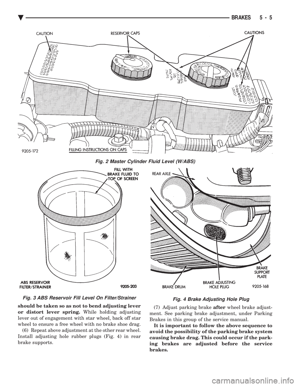
contaminating the brake fluid. (3) Inspect the brake fluid to see if it is at the proper
level, see instructions on top of reservoir. (FILL TO
TOP OF WHITE SCREEN ON FRONT
FILTER/STRAINER.) (4) Fill reservoir with brake fluid to top of screen
(Fig. 3) on the filter/strainer located in brake fluid
reservoir. Only use brake fluid conforming to DOT 3
specifications such as Mopar tor equivalent.
(5) Replace brake fluid reservoir caps.
ADJUSTING REAR SERVICE BRAKES
Normally, self adjusting drum brakes will not
require manual brake shoe adjustment. Al-
though in the event of a brake reline it is advis-
able to make the initial adjustment manually to
speed up the adjusting time. (1) Raise the vehicle so all wheels are free to turn.
See Hoisting Recommendations in the Lubrication And
Maintenance Section, at the front of this service
manual. (2) Remove rear brake adjusting hole rubber plug
(Fig. 4), from the rear brake shoe support plate. (3) Be sure parking brake lever is fully re-
leased. Then back off parking brake cable adjust-
ment so there is slack in the cable. (4) Insert Brake Adjuster, Special Tool C-3784, (Fig.
5) or equivalent through the adjusting hole in support
plate and against star wheel of adjusting screw. Move
handle of tool upward until a slight drag is felt when
the road wheel is rotated. (5) Insert a thin screwdriver or piece of welding rod
into brake adjusting hole (Fig. 5). Push adjusting lever
out of engagement with star wheel. Care
Fig. 1 Master Cylinder Fluid Level (All Except AC/AY
Body W/ABS)
5 - 4 BRAKES Ä
Page 155 of 2438
should be taken so as not to bend adjusting lever
or distort lever spring. While holding adjusting
lever out of engagement with star wheel, back off star
wheel to ensure a free wheel with no brake shoe drag. (6) Repeat above adjustment at the other rear wheel.
Install adjusting hole rubber plugs (Fig. 4) in rear
brake supports. (7) Adjust parking brake
afterwheel brake adjust-
ment. See parking brake adjustment, under Parking
Brakes in this group of the service manual. It is important to follow the above sequence to
avoid the possibility of the parking brake system
causing brake drag. This could occur if the park-
ing brakes are adjusted before the service
brakes.
Fig. 4 Brake Adjusting Hole Plug
Fig. 2 Master Cylinder Fluid Level (W/ABS)
Fig. 3 ABS Reservoir Fill Level On Filter/Strainer
Ä BRAKES 5 - 5
Page 169 of 2438
Install grease cap and wheel and tire assemblies.
Tighten wheel stud nuts to 115 N Im (85 ft. lbs.)
torque on all models. Install wheel covers.
BRAKE SHOE ASSEMBLIES
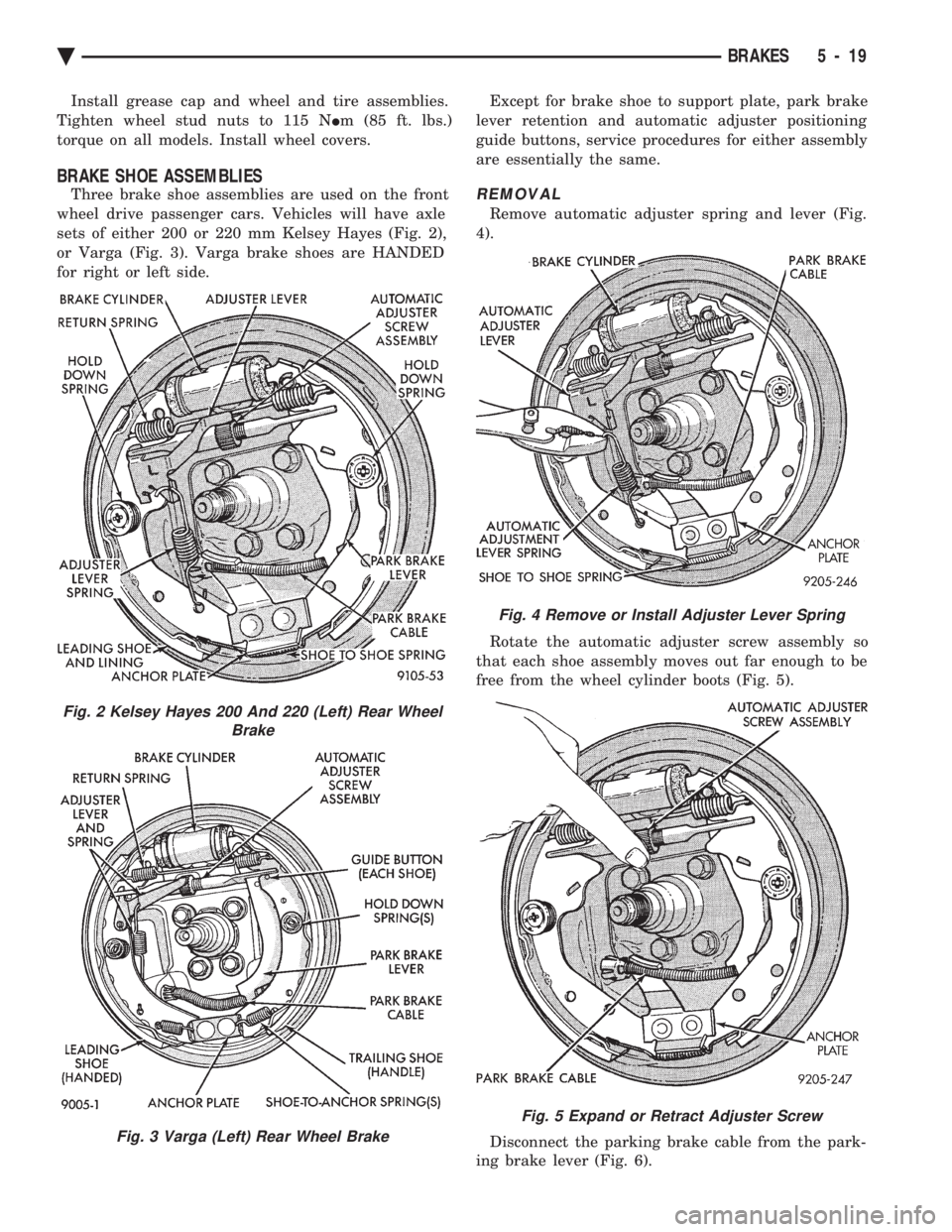
Three brake shoe assemblies are used on the front
wheel drive passenger cars. Vehicles will have axle
sets of either 200 or 220 mm Kelsey Hayes (Fig. 2),
or Varga (Fig. 3). Varga brake shoes are HANDED
for right or left side. Except for brake shoe to support plate, park brake
lever retention and automatic adjuster positioning
guide buttons, service procedures for either assembly
are essentially the same.REMOVAL
Remove automatic adjuster spring and lever (Fig.
4).
Rotate the automatic adjuster screw assembly so
that each shoe assembly moves out far enough to be
free from the wheel cylinder boots (Fig. 5).
Disconnect the parking brake cable from the park-
ing brake lever (Fig. 6).
Fig. 2 Kelsey Hayes 200 And 220 (Left) Rear Wheel Brake
Fig. 3 Varga (Left) Rear Wheel Brake
Fig. 4 Remove or Install Adjuster Lever Spring
Fig. 5 Expand or Retract Adjuster Screw
Ä BRAKES 5 - 19
Page 170 of 2438
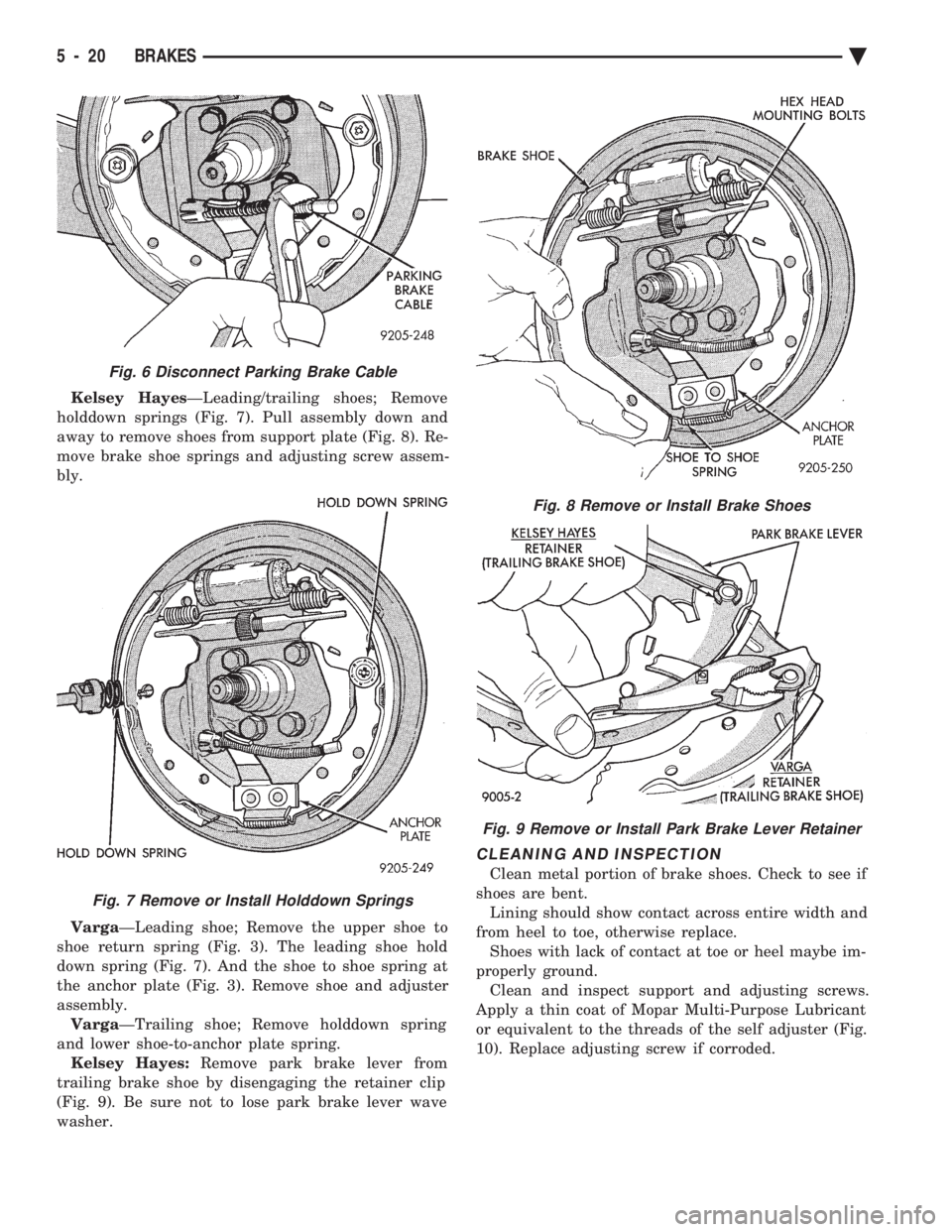
Kelsey Hayes ÐLeading/trailing shoes; Remove
holddown springs (Fig. 7). Pull assembly down and
away to remove shoes from support plate (Fig. 8). Re-
move brake shoe springs and adjusting screw assem-
bly.
Varga ÐLeading shoe; Remove the upper shoe to
shoe return spring (Fig. 3). The leading shoe hold
down spring (Fig. 7). And the shoe to shoe spring at
the anchor plate (Fig. 3). Remove shoe and adjuster
assembly. Varga ÐTrailing shoe; Remove holddown spring
and lower shoe-to-anchor plate spring. Kelsey Hayes: Remove park brake lever from
trailing brake shoe by disengaging the retainer clip
(Fig. 9). Be sure not to lose park brake lever wave
washer.
CLEANING AND INSPECTION
Clean metal portion of brake shoes. Check to see if
shoes are bent. Lining should show contact across entire width and
from heel to toe, otherwise replace. Shoes with lack of contact at toe or heel maybe im-
properly ground. Clean and inspect support and adjusting screws.
Apply a thin coat of Mopar Multi-Purpose Lubricant
or equivalent to the threads of the self adjuster (Fig.
10). Replace adjusting screw if corroded.
Fig. 6 Disconnect Parking Brake Cable
Fig. 7 Remove or Install Holddown Springs
Fig. 8 Remove or Install Brake Shoes
Fig. 9 Remove or Install Park Brake Lever Retainer
5 - 20 BRAKES Ä
Page 171 of 2438
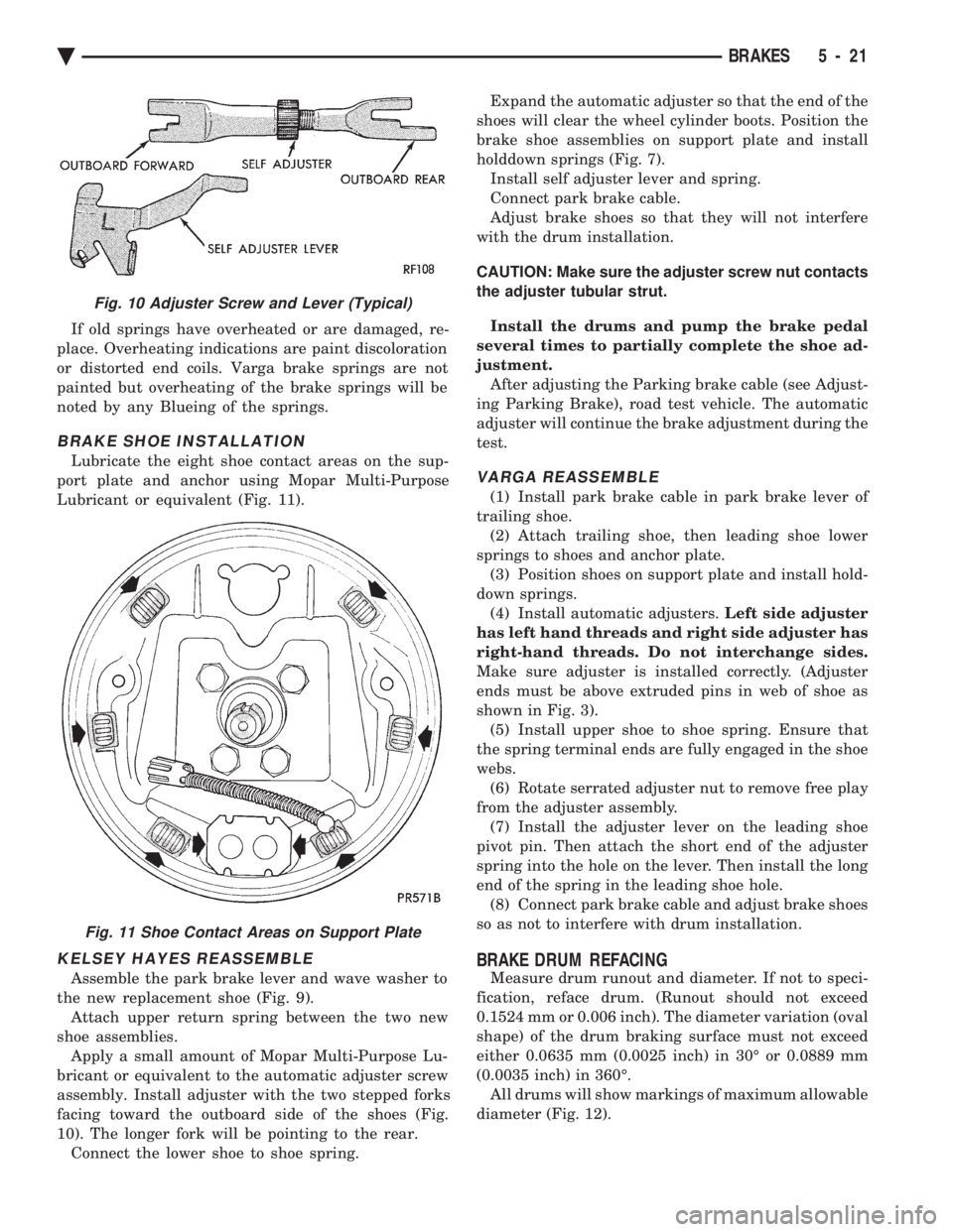
If old springs have overheated or are damaged, re-
place. Overheating indications are paint discoloration
or distorted end coils. Varga brake springs are not
painted but overheating of the brake springs will be
noted by any Blueing of the springs.
BRAKE SHOE INSTALLATION
Lubricate the eight shoe contact areas on the sup-
port plate and anchor using Mopar Multi-Purpose
Lubricant or equivalent (Fig. 11).
KELSEY HAYES REASSEMBLE
Assemble the park brake lever and wave washer to
the new replacement shoe (Fig. 9). Attach upper return spring between the two new
shoe assemblies. Apply a small amount of Mopar Multi-Purpose Lu-
bricant or equivalent to the automatic adjuster screw
assembly. Install adjuster with the two stepped forks
facing toward the outboard side of the shoes (Fig.
10). The longer fork will be pointing to the rear. Connect the lower shoe to shoe spring. Expand the automatic adjuster so that the end of the
shoes will clear the wheel cylinder boots. Position the
brake shoe assemblies on support plate and install
holddown springs (Fig. 7). Install self adjuster lever and spring.
Connect park brake cable.
Adjust brake shoes so that they will not interfere
with the drum installation.
CAUTION: Make sure the adjuster screw nut contacts
the adjuster tubular strut.
Install the drums and pump the brake pedal
several times to partially complete the shoe ad-
justment. After adjusting the Parking brake cable (see Adjust-
ing Parking Brake), road test vehicle. The automatic
adjuster will continue the brake adjustment during the
test.
VARGA REASSEMBLE
(1) Install park brake cable in park brake lever of
trailing shoe. (2) Attach trailing shoe, then leading shoe lower
springs to shoes and anchor plate. (3) Position shoes on support plate and install hold-
down springs. (4) Install automatic adjusters. Left side adjuster
has left hand threads and right side adjuster has
right-hand threads. Do not interchange sides.
Make sure adjuster is installed correctly. (Adjuster
ends must be above extruded pins in web of shoe as
shown in Fig. 3). (5) Install upper shoe to shoe spring. Ensure that
the spring terminal ends are fully engaged in the shoe
webs. (6) Rotate serrated adjuster nut to remove free play
from the adjuster assembly. (7) Install the adjuster lever on the leading shoe
pivot pin. Then attach the short end of the adjuster
spring into the hole on the lever. Then install the long
end of the spring in the leading shoe hole. (8) Connect park brake cable and adjust brake shoes
so as not to interfere with drum installation.
BRAKE DRUM REFACING
Measure drum runout and diameter. If not to speci-
fication, reface drum. (Runout should not exceed
0.1524 mm or 0.006 inch). The diameter variation (oval
shape) of the drum braking surface must not exceed
either 0.0635 mm (0.0025 inch) in 30É or 0.0889 mm
(0.0035 inch) in 360É. All drums will show markings of maximum allowable
diameter (Fig. 12).
Fig. 10 Adjuster Screw and Lever (Typical)
Fig. 11 Shoe Contact Areas on Support Plate
Ä BRAKES 5 - 21
Page 175 of 2438
BRAKE SUPPORT ASSEMBLY
REMOVAL
Back off parking brake adjusting nut to provide
slack in cable. With wheel and brake drum removed, disconnect
hydraulic tube from wheel cylinder.Disconnect park-
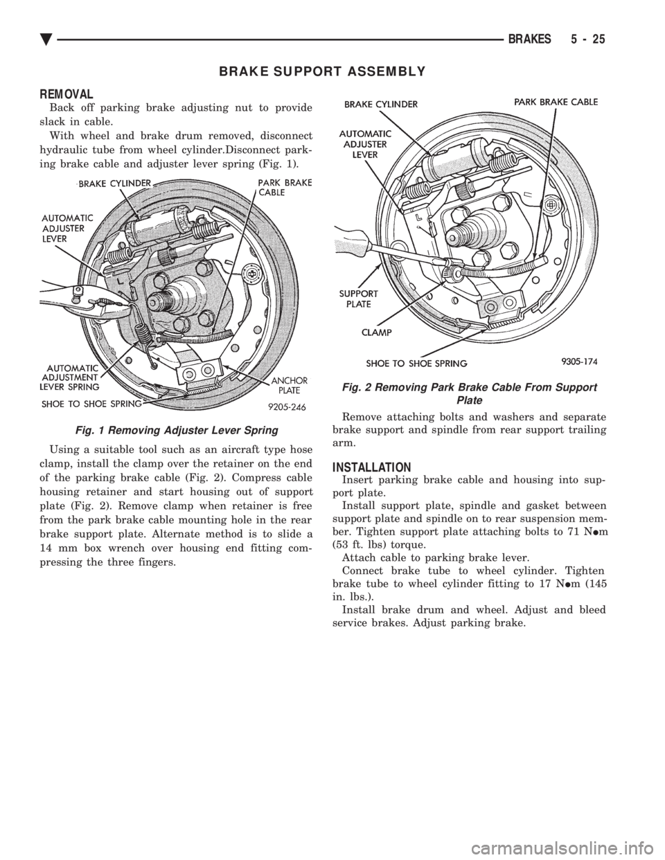
ing brake cable and adjuster lever spring (Fig. 1).
Using a suitable tool such as an aircraft type hose
clamp, install the clamp over the retainer on the end
of the parking brake cable (Fig. 2). Compress cable
housing retainer and start housing out of support
plate (Fig. 2). Remove clamp when retainer is free
from the park brake cable mounting hole in the rear
brake support plate. Alternate method is to slide a
14 mm box wrench over housing end fitting com-
pressing the three fingers. Remove attaching bolts and washers and separate
brake support and spindle from rear support trailing
arm.
INSTALLATION
Insert parking brake cable and housing into sup-
port plate. Install support plate, spindle and gasket between
support plate and spindle on to rear suspension mem-
ber. Tighten support plate attaching bolts to 71 N Im
(53 ft. lbs) torque. Attach cable to parking brake lever.
Connect brake tube to wheel cylinder. Tighten
brake tube to wheel cylinder fitting to 17 N Im (145
in. lbs.). Install brake drum and wheel. Adjust and bleed
service brakes. Adjust parking brake.
Fig. 1 Removing Adjuster Lever Spring
Fig. 2 Removing Park Brake Cable From Support Plate
Ä BRAKES 5 - 25