weight CHEVROLET DYNASTY 1993 Service Manual
[x] Cancel search | Manufacturer: CHEVROLET, Model Year: 1993, Model line: DYNASTY, Model: CHEVROLET DYNASTY 1993Pages: 2438, PDF Size: 74.98 MB
Page 43 of 2438
TOWING RECOMMENDATIONS
RECOMMENDED TOWING EQUIPMENT
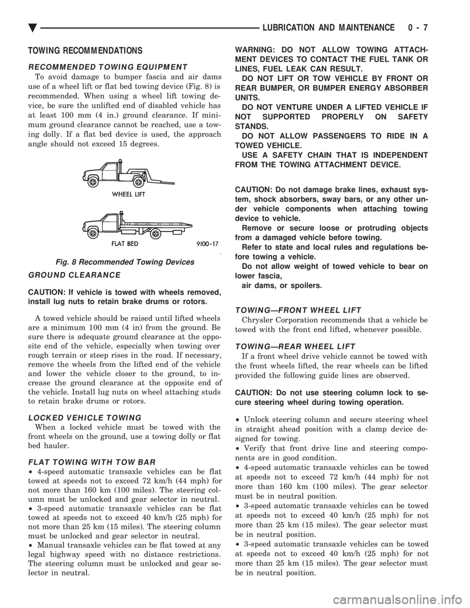
To avoid damage to bumper fascia and air dams
use of a wheel lift or flat bed towing device (Fig. 8) is
recommended. When using a wheel lift towing de-
vice, be sure the unlifted end of disabled vehicle has
at least 100 mm (4 in.) ground clearance. If mini-
mum ground clearance cannot be reached, use a tow-
ing dolly. If a flat bed device is used, the approach
angle should not exceed 15 degrees.
GROUND CLEARANCE
CAUTION: If vehicle is towed with wheels removed,
install lug nuts to retain brake drums or rotors.
A towed vehicle should be raised until lifted wheels
are a minimum 100 mm (4 in) from the ground. Be
sure there is adequate ground clearance at the oppo-
site end of the vehicle, especially when towing over
rough terrain or steep rises in the road. If necessary,
remove the wheels from the lifted end of the vehicle
and lower the vehicle closer to the ground, to in-
crease the ground clearance at the opposite end of
the vehicle. Install lug nuts on wheel attaching studs
to retain brake drums or rotors.
LOCKED VEHICLE TOWING
When a locked vehicle must be towed with the
front wheels on the ground, use a towing dolly or flat
bed hauler.
FLAT TOWING WITH TOW BAR
² 4-speed automatic transaxle vehicles can be flat
towed at speeds not to exceed 72 km/h (44 mph) for
not more than 160 km (100 miles). The steering col-
umn must be unlocked and gear selector in neutral.
² 3-speed automatic transaxle vehicles can be flat
towed at speeds not to exceed 40 km/h (25 mph) for
not more than 25 km (15 miles). The steering column
must be unlocked and gear selector in neutral.
² Manual transaxle vehicles can be flat towed at any
legal highway speed with no distance restrictions.
The steering column must be unlocked and gear se-
lector in neutral. WARNING: DO NOT ALLOW TOWING ATTACH-
MENT DEVICES TO CONTACT THE FUEL TANK OR
LINES, FUEL LEAK CAN RESULT. DO NOT LIFT OR TOW VEHICLE BY FRONT OR
REAR BUMPER, OR BUMPER ENERGY ABSORBER
UNITS. DO NOT VENTURE UNDER A LIFTED VEHICLE IF
NOT SUPPORTED PROPERLY ON SAFETY
STANDS. DO NOT ALLOW PASSENGERS TO RIDE IN A
TOWED VEHICLE. USE A SAFETY CHAIN THAT IS INDEPENDENT
FROM THE TOWING ATTACHMENT DEVICE.
CAUTION: Do not damage brake lines, exhaust sys-
tem, shock absorbers, sway bars, or any other un-
der vehicle components when attaching towing
device to vehicle. Remove or secure loose or protruding objects
from a damaged vehicle before towing. Refer to state and local rules and regulations be-
fore towing a vehicle. Do not allow weight of towed vehicle to bear on
lower fascia, air dams, or spoilers.
TOWINGÐFRONT WHEEL LIFT
Chrysler Corporation recommends that a vehicle be
towed with the front end lifted, whenever possible.
TOWINGÐREAR WHEEL LIFT
If a front wheel drive vehicle cannot be towed with
the front wheels lifted, the rear wheels can be lifted
provided the following guide lines are observed.
CAUTION: Do not use steering column lock to se-
cure steering wheel during towing operation.
² Unlock steering column and secure steering wheel
in straight ahead position with a clamp device de-
signed for towing.
² Verify that front drive line and steering compo-
nents are in good condition.
² 4-speed automatic transaxle vehicles can be towed
at speeds not to exceed 72 km/h (44 mph) for not
more than 160 km (100 miles). The gear selector
must be in neutral position.
² 3-speed automatic transaxle vehicles can be towed
at speeds not to exceed 40 km/h (25 mph) for not
more than 25 km (15 miles). The gear selector must
be in neutral position.
² 3-speed automatic transaxle vehicles can be towed
at speeds not to exceed 40 km/h (25 mph) for not
more than 25 km (15 miles). The gear selector must
be in neutral position.
Fig. 8 Recommended Towing Devices
Ä LUBRICATION AND MAINTENANCE 0 - 7
Page 69 of 2438
Inspect lower control arm for distortion. Check
bushings for severe deterioration.
INSTALLATION (ASSEMBLY)
(1) Position the lower control arm into the cross-
member. Install front and rear pivot bushing to
crossmember attaching bolts. Then loosely assemble
nuts to bolts (Fig. 2). (2) Install ball joint stud into steering knuckle and
install clamp bolt (Fig. 1). Tighten clamp bolt to 145
N Im (105 ft. lbs.).
(3) Position sway bar and bushings against the
lower control arms. Install sway bar to control arm
retainers. Install retainer bolts and tighten to 70
N Im (50 ft. lbs.).
(4) Lower vehicle so the suspension is supporting
vehicles weight (control arm at design height).
Tighten the lower control arm to crossmember at-
taching bolts to 169 N Im (125 ft. lbs.) torque.
LOWER CONTROL ARM PIVOT BUSHINGS
When performing the replacement procedure on the
lower control arm pivot bushings, the following se-
quence must be followed. When removing the pivot
bushings from the lower control arm, the large bush-
ing must be removed first then the small bushing.
When installing the pivot bushings into the lower
control arm, the small bushing must be installed
first then the large bushing. This sequence must be
used when removal and replacement of bushings is
done using Bushing Remover/Installer, Special Tool
6602.
LARGE BUSHING
REMOVE
(1) Position and clamp lower control arm in a vise.
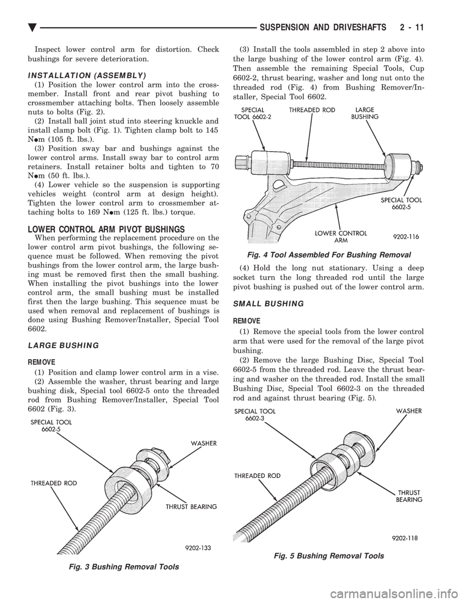
(2) Assemble the washer, thrust bearing and large
bushing disk, Special tool 6602-5 onto the threaded
rod from Bushing Remover/Installer, Special Tool
6602 (Fig. 3). (3) Install the tools assembled in step 2 above into
the large bushing of the lower control arm (Fig. 4).
Then assemble the remaining Special Tools, Cup
6602-2, thrust bearing, washer and long nut onto the
threaded rod (Fig. 4) from Bushing Remover/In-
staller, Special Tool 6602.
(4) Hold the long nut stationary. Using a deep
socket turn the long threaded rod until the large
pivot bushing is pushed out of the lower control arm.
SMALL BUSHING
REMOVE
(1) Remove the special tools from the lower control
arm that were used for the removal of the large pivot
bushing. (2) Remove the large Bushing Disc, Special Tool
6602-5 from the threaded rod. Leave the thrust bear-
ing and washer on the threaded rod. Install the small
Bushing Disc, Special Tool 6602-3 on the threaded
rod and against thrust bearing (Fig. 5).
Fig. 3 Bushing Removal Tools
Fig. 4 Tool Assembled For Bushing Removal
Fig. 5 Bushing Removal Tools
Ä SUSPENSION AND DRIVESHAFTS 2 - 11
Page 71 of 2438
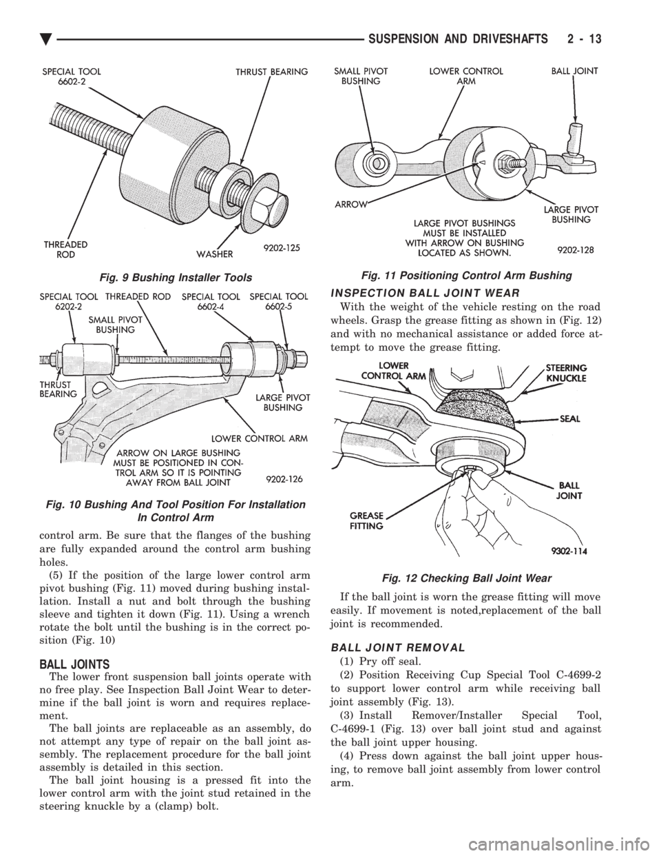
control arm. Be sure that the flanges of the bushing
are fully expanded around the control arm bushing
holes. (5) If the position of the large lower control arm
pivot bushing (Fig. 11) moved during bushing instal-
lation. Install a nut and bolt through the bushing
sleeve and tighten it down (Fig. 11). Using a wrench
rotate the bolt until the bushing is in the correct po-
sition (Fig. 10)
BALL JOINTS
The lower front suspension ball joints operate with
no free play. See Inspection Ball Joint Wear to deter-
mine if the ball joint is worn and requires replace-
ment. The ball joints are replaceable as an assembly, do
not attempt any type of repair on the ball joint as-
sembly. The replacement procedure for the ball joint
assembly is detailed in this section. The ball joint housing is a pressed fit into the
lower control arm with the joint stud retained in the
steering knuckle by a (clamp) bolt.
INSPECTION BALL JOINT WEAR
With the weight of the vehicle resting on the road
wheels. Grasp the grease fitting as shown in (Fig. 12)
and with no mechanical assistance or added force at-
tempt to move the grease fitting.
If the ball joint is worn the grease fitting will move
easily. If movement is noted,replacement of the ball
joint is recommended.
BALL JOINT REMOVAL
(1) Pry off seal.
(2) Position Receiving Cup Special Tool C-4699-2
to support lower control arm while receiving ball
joint assembly (Fig. 13). (3) Install Remover/Installer Special Tool,
C-4699-1 (Fig. 13) over ball joint stud and against
the ball joint upper housing. (4) Press down against the ball joint upper hous-
ing, to remove ball joint assembly from lower control
arm.
Fig. 9 Bushing Installer Tools
Fig. 10 Bushing And Tool Position For Installation In Control Arm
Fig. 11 Positioning Control Arm Bushing
Fig. 12 Checking Ball Joint Wear
Ä SUSPENSION AND DRIVESHAFTS 2 - 13
Page 83 of 2438
DRIVESHAFTS INDEX
page page
C/V Joint Boots Handling and Cleaning ........ 44
Damper Weights ......................... 48
Driveshaft Identification .................... 27
Driveshaft Positioning Specifications .......... 48
Driveshaft Reconditioning Procedure .......... 31
Driveshafts, Remove Install ................. 27 General Information
....................... 25
Inner C/V Joint .......................... 32
Intermediate Shaft Assembly Recondition ...... 41
Outer C/V Joint .......................... 37
Service Procedures ....................... 27
GENERAL INFORMATION
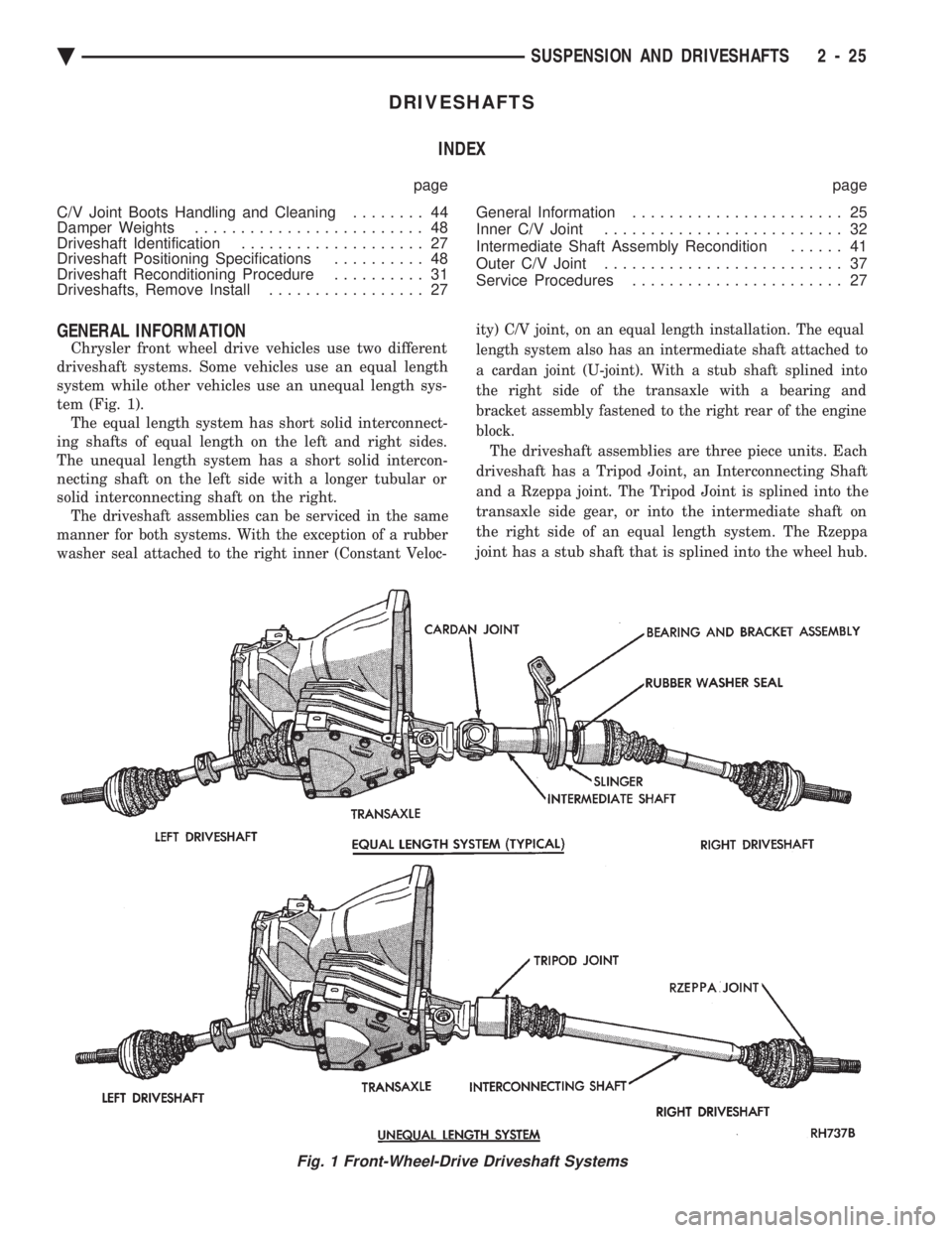
Chrysler front wheel drive vehicles use two different
driveshaft systems. Some vehicles use an equal length
system while other vehicles use an unequal length sys-
tem (Fig. 1). The equal length system has short solid interconnect-
ing shafts of equal length on the left and right sides.
The unequal length system has a short solid intercon-
necting shaft on the left side with a longer tubular or
solid interconnecting shaft on the right.
The driveshaft assemblies can be serviced in the same
manner for both systems. With the exception of a rubber
washer seal attached to the right inner (Constant Veloc- ity) C/V joint, on an equal length installation. The equal
length system also has an intermediate shaft attached to
a cardan joint (U-joint). With a stub shaft splined into
the right side of the transaxle with a bearing and
bracket assembly fastened to the right rear of the engine
block.
The driveshaft assemblies are three piece units. Each
driveshaft has a Tripod Joint, an Interconnecting Shaft
and a Rzeppa joint. The Tripod Joint is splined into the
transaxle side gear, or into the intermediate shaft on
the right side of an equal length system. The Rzeppa
joint has a stub shaft that is splined into the wheel hub.
Fig. 1 Front-Wheel-Drive Driveshaft Systems
Ä SUSPENSION AND DRIVESHAFTS 2 - 25
Page 95 of 2438
the plastic retaining collar. Carefully insert each of the
tripod rollers into the retaining collar, one at a time
while holding the interconnecting shaft on an angle.
Carefully push down on the shaft until the rollers are
locked into retaining collar in the housing.(4) Position the boot over the boot retaining groove
in the housing and clamp in place. See Boots Install.
S.S.G.
(1) Distribute 1/2 the amount of the grease provided
into the housing and the remaining amount into the
boot. (2) Position the spring in the housing spring pocket
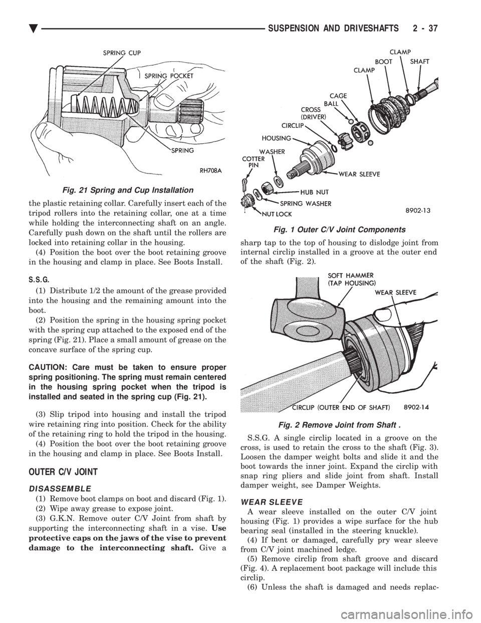
with the spring cup attached to the exposed end of the
spring (Fig. 21). Place a small amount of grease on the
concave surface of the spring cup.
CAUTION: Care must be taken to ensure proper
spring positioning. The spring must remain centered
in the housing spring pocket when the tripod is
installed and seated in the spring cup (Fig. 21).
(3) Slip tripod into housing and install the tripod
wire retaining ring into position. Check for the ability
of the retaining ring to hold the tripod in the housing. (4) Position the boot over the boot retaining groove
in the housing and clamp in place. See Boots Install.
OUTER C/V JOINT
DISASSEMBLE
(1) Remove boot clamps on boot and discard (Fig. 1).
(2) Wipe away grease to expose joint.
(3) G.K.N. Remove outer C/V Joint from shaft by
supporting the interconnecting shaft in a vise. Use
protective caps on the jaws of the vise to prevent
damage to the interconnecting shaft. Give a sharp tap to the top of housing to dislodge joint from
internal circlip installed in a groove at the outer end
of the shaft (Fig. 2).
S.S.G. A single circlip located in a groove on the
cross, is used to retain the cross to the shaft (Fig. 3).
Loosen the damper weight bolts and slide it and the
boot towards the inner joint. Expand the circlip with
snap ring pliers and slide joint from shaft. Install
damper weight, see Damper Weights.WEAR SLEEVE
A wear sleeve installed on the outer C/V joint
housing (Fig. 1) provides a wipe surface for the hub
bearing seal (installed in the steering knuckle). (4) If bent or damaged, carefully pry wear sleeve
from C/V joint machined ledge. (5) Remove circlip from shaft groove and discard
(Fig. 4). A replacement boot package will include this
circlip. (6) Unless the shaft is damaged and needs replac-
Fig. 1 Outer C/V Joint Components
Fig. 2 Remove Joint from Shaft .
Fig. 21 Spring and Cup Installation
Ä SUSPENSION AND DRIVESHAFTS 2 - 37
Page 106 of 2438
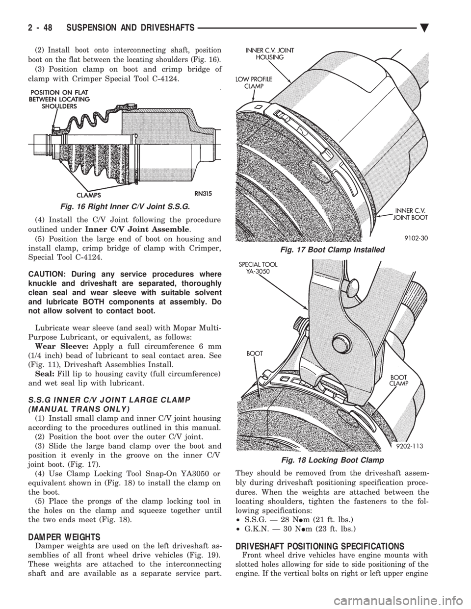
(2) Install boot onto interconnecting shaft, position
boot on the flat between the locating shoulders (Fig. 16).
(3) Position clamp on boot and crimp bridge of
clamp with Crimper Special Tool C-4124.
(4) Install the C/V Joint following the procedure
outlined under Inner C/V Joint Assemble .
(5) Position the large end of boot on housing and
install clamp, crimp bridge of clamp with Crimper,
Special Tool C-4124.
CAUTION: During any service procedures where
knuckle and driveshaft are separated, thoroughly
clean seal and wear sleeve with suitable solvent
and lubricate BOTH components at assembly. Do
not allow solvent to contact boot.
Lubricate wear sleeve (and seal) with Mopar Multi-
Purpose Lubricant, or equivalent, as follows: Wear Sleeve: Apply a full circumference 6 mm
(1/4 inch) bead of lubricant to seal contact area. See
(Fig. 11), Driveshaft Assemblies Install. Seal: Fill lip to housing cavity (full circumference)
and wet seal lip with lubricant.
S.S.G INNER C/V JOINT LARGE CLAMP (MANUAL TRANS ONLY)
(1) Install small clamp and inner C/V joint housing
according to the procedures outlined in this manual. (2) Position the boot over the outer C/V joint.
(3) Slide the large band clamp over the boot and
position it evenly in the groove on the inner C/V
joint boot. (Fig. 17). (4) Use Clamp Locking Tool Snap-On YA3050 or
equivalent shown in (Fig. 18) to install the clamp on
the boot. (5) Place the prongs of the clamp locking tool in
the holes on the clamp and squeeze together until
the two ends meet (Fig. 18).
DAMPER WEIGHTS
Damper weights are used on the left driveshaft as-
semblies of all front wheel drive vehicles (Fig. 19).
These weights are attached to the interconnecting
shaft and are available as a separate service part. They should be removed from the driveshaft assem-
bly during driveshaft positioning specification proce-
dures. When the weights are attached between the
locating shoulders, tighten the fasteners to the fol-
lowing specifications:
² S.S.G. Ð 28 N Im (21 ft. lbs.)
² G.K.N. Ð 30 N Im (23 ft. lbs.)DRIVESHAFT POSITIONING SPECIFICATIONS
Front wheel drive vehicles have engine mounts with
slotted holes allowing for side to side positioning of the
engine. If the vertical bolts on right or left upper engine
Fig. 16 Right Inner C/V Joint S.S.G.
Fig. 17 Boot Clamp Installed
Fig. 18 Locking Boot Clamp
2 - 48 SUSPENSION AND DRIVESHAFTS Ä
Page 107 of 2438
mount have been loosened for any reason, or if vehicle
has experienced front structural damage, driveshaft
lengths must be checked and corrected, if required. A
shorter than required driveshaft length can result in ob-
jectionable noise. A longer than required driveshaft
length may result in potential damage.
Use of the following procedure will ensure satisfac-
tory driveshaft engagement under all normal vehicle
operating conditions. (1) The vehicle must be completely assembled.
Front wheels must be properly aligned and in the
straight ahead position. The vehicle must be in a po-
sition so that the full weight of the body is distrib-
uted to all four tires. A platform hoist, or front end
alignment rack, is recommended.
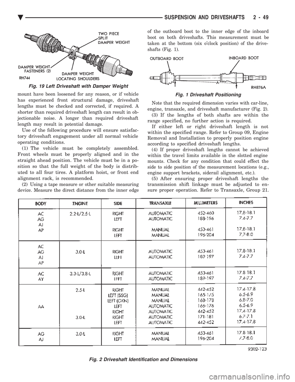
(2) Using a tape measure or other suitable measuring
device. Measure the direct distance from the inner edge of the outboard boot to the inner edge of the inboard
boot on both driveshafts. This measurement must be
taken at the bottom (six o'clock position) of the drive-
shafts (Fig. 1).
Note that the required dimension varies with car-line,
engine, transaxle, and driveshaft manufacturer (Fig. 2).
(3) If the lengths of both shafts are within the
range specified, no further action is required. If either left or right driveshaft length is not
within the specified range. Refer to Group 09, Engine
Removal and Installation to properly position engine
according to specified driveshaft lengths.
(4) If proper driveshaft lengths cannot be achieved
within the travel limits available in the slotted engine
mounts. Check for any condition that could effect the
side to side position of the measurement locations (e.g.,
engine support brackets, siderail alignment, etc.).
(5) After ensuring proper driveshaft lengths the
transmission shift linkage must be adjusted to en-
sure proper operation. Refer to Transaxle, Group 21.
Fig. 2 Driveshaft Identification and Dimensions
Fig. 19 Left Driveshaft with Damper Weight
Fig. 1 Driveshaft Positioning
Ä SUSPENSION AND DRIVESHAFTS 2 - 49
Page 109 of 2438
to the road surface. While being able to twist as one
wheel moves vertically with respect to the other.Roll resistance is provided partly by the axle's re-
sistance to twist. But primarily by a torque tube or
rod (depending on the suspension option called for)
running through the channel and attached rigidly to
its end plates by welding. Because the torque tube/
rod is an integral part of the axle assembly, it cannot
be individually replaced. The spindles are bolted to the axle end (spindle
mounting) plates and can be individually replaced if
required. Rear wheel alignment changes require the
use of shims between the spindle and axle end plates.
SHOCK ABSORBERS
REMOVAL
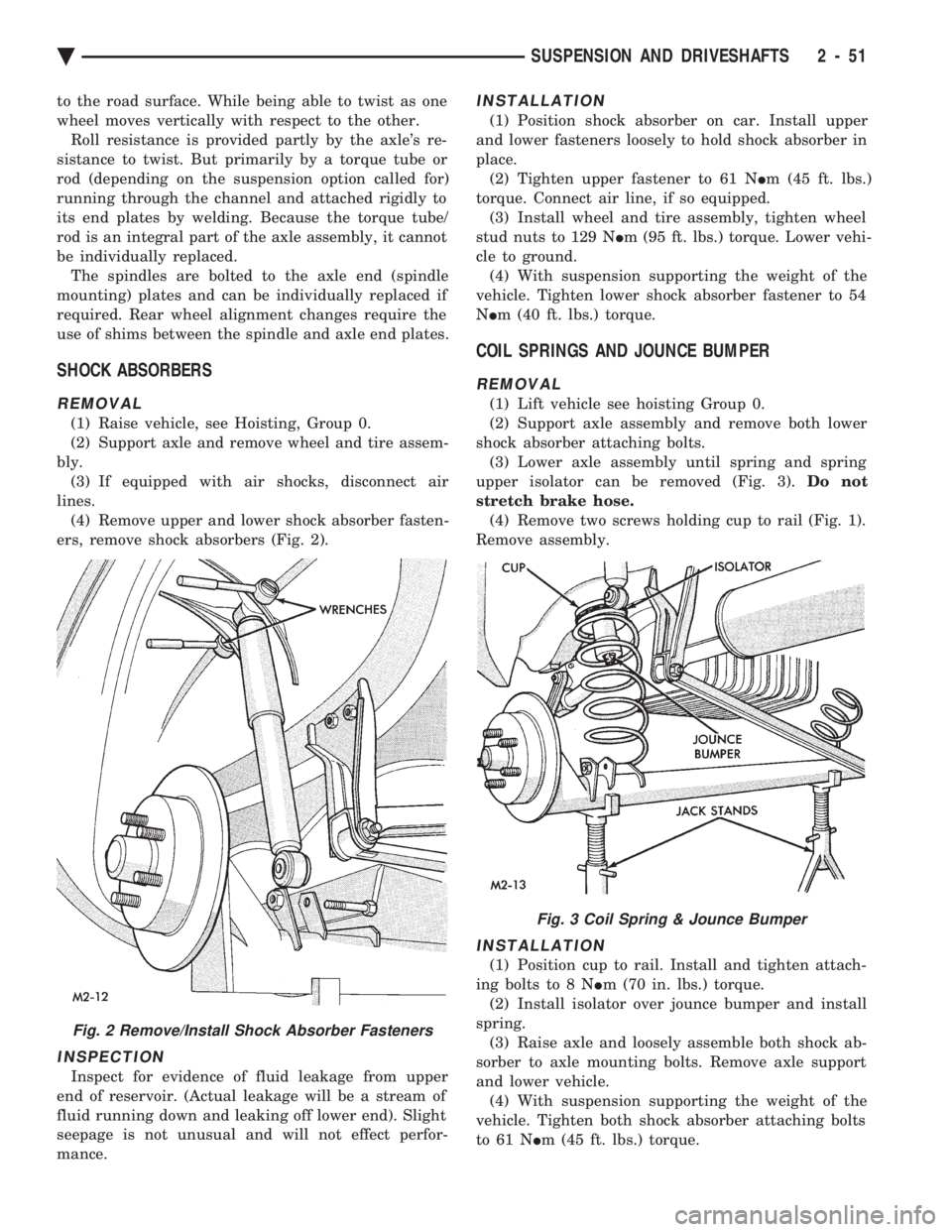
(1) Raise vehicle, see Hoisting, Group 0.
(2) Support axle and remove wheel and tire assem-
bly. (3) If equipped with air shocks, disconnect air
lines. (4) Remove upper and lower shock absorber fasten-
ers, remove shock absorbers (Fig. 2).
INSPECTION
Inspect for evidence of fluid leakage from upper
end of reservoir. (Actual leakage will be a stream of
fluid running down and leaking off lower end). Slight
seepage is not unusual and will not effect perfor-
mance.
INSTALLATION
(1) Position shock absorber on car. Install upper
and lower fasteners loosely to hold shock absorber in
place. (2) Tighten upper fastener to 61 N Im (45 ft. lbs.)
torque. Connect air line, if so equipped. (3) Install wheel and tire assembly, tighten wheel
stud nuts to 129 N Im (95 ft. lbs.) torque. Lower vehi-
cle to ground. (4) With suspension supporting the weight of the
vehicle. Tighten lower shock absorber fastener to 54
N Im (40 ft. lbs.) torque.
COIL SPRINGS AND JOUNCE BUMPER
REMOVAL
(1) Lift vehicle see hoisting Group 0.
(2) Support axle assembly and remove both lower
shock absorber attaching bolts. (3) Lower axle assembly until spring and spring
upper isolator can be removed (Fig. 3). Do not
stretch brake hose. (4) Remove two screws holding cup to rail (Fig. 1).
Remove assembly.
INSTALLATION
(1) Position cup to rail. Install and tighten attach-
ing bolts to 8 N Im (70 in. lbs.) torque.
(2) Install isolator over jounce bumper and install
spring. (3) Raise axle and loosely assemble both shock ab-
sorber to axle mounting bolts. Remove axle support
and lower vehicle. (4) With suspension supporting the weight of the
vehicle. Tighten both shock absorber attaching bolts
to 61 N Im (45 ft. lbs.) torque.
Fig. 2 Remove/Install Shock Absorber Fasteners
Fig. 3 Coil Spring & Jounce Bumper
Ä SUSPENSION AND DRIVESHAFTS 2 - 51
Page 112 of 2438
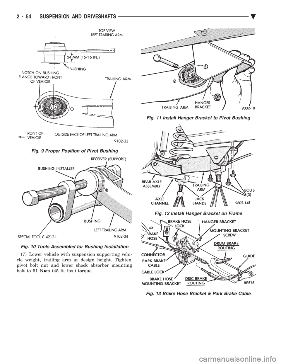
(7) Lower vehicle with suspension supporting vehi-
cle weight, trailing arm at design height. Tighten
pivot bolt nut and lower shock absorber mounting
bolt to 61 N Im (45 ft. lbs.) torque.
Fig. 9 Proper Position of Pivot Bushing
Fig. 10 Tools Assembled for Bushing Installation
Fig. 11 Install Hanger Bracket to Pivot Bushing
Fig. 12 Install Hanger Bracket on Frame
Fig. 13 Brake Hose Bracket & Park Brake Cable
2 - 54 SUSPENSION AND DRIVESHAFTS Ä
Page 114 of 2438
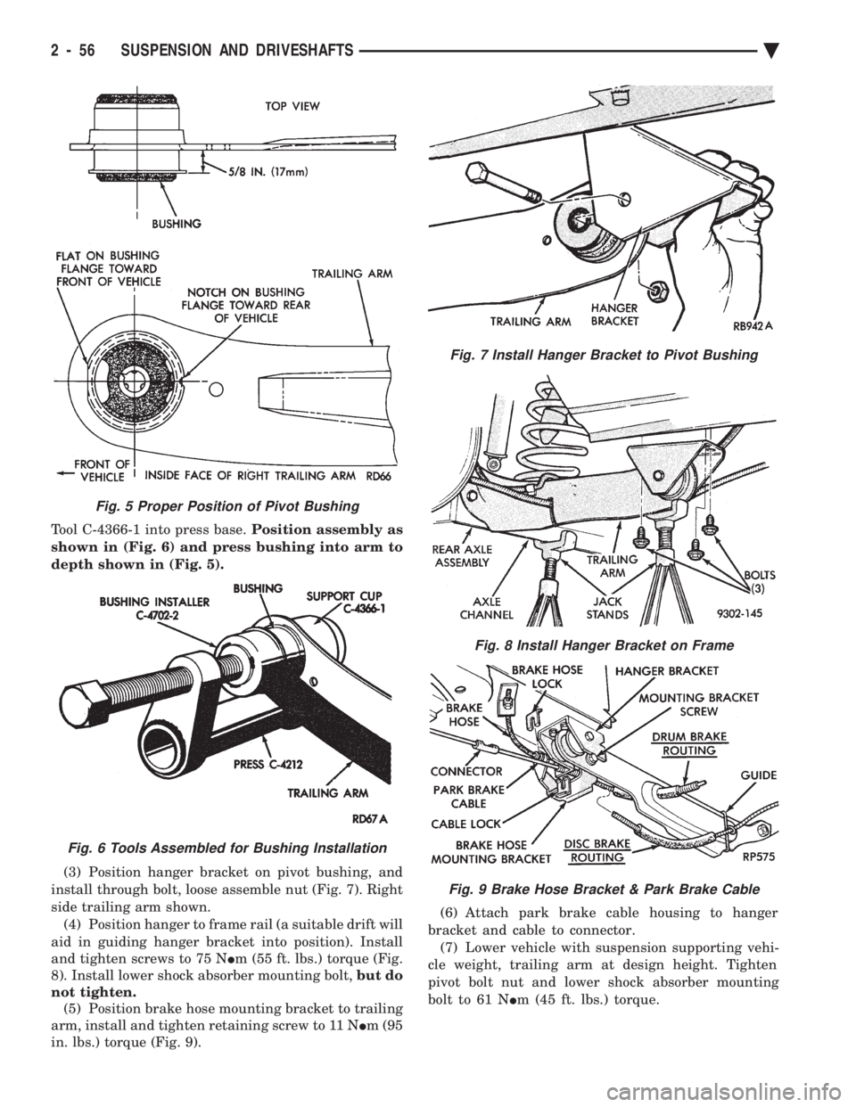
Tool C-4366-1 into press base. Position assembly as
shown in (Fig. 6) and press bushing into arm to
depth shown in (Fig. 5).
(3) Position hanger bracket on pivot bushing, and
install through bolt, loose assemble nut (Fig. 7). Right
side trailing arm shown. (4) Position hanger to frame rail (a suitable drift will
aid in guiding hanger bracket into position). Install
and tighten screws to 75 N Im (55 ft. lbs.) torque (Fig.
8). Install lower shock absorber mounting bolt, but do
not tighten. (5) Position brake hose mounting bracket to trailing
arm, install and tighten retaining screw to 11 N Im (95
in. lbs.) torque (Fig. 9). (6) Attach park brake cable housing to hanger
bracket and cable to connector. (7) Lower vehicle with suspension supporting vehi-
cle weight, trailing arm at design height. Tighten
pivot bolt nut and lower shock absorber mounting
bolt to 61 N Im (45 ft. lbs.) torque.
Fig. 7 Install Hanger Bracket to Pivot Bushing
Fig. 8 Install Hanger Bracket on Frame
Fig. 9 Brake Hose Bracket & Park Brake Cable
Fig. 5 Proper Position of Pivot Bushing
Fig. 6 Tools Assembled for Bushing Installation
2 - 56 SUSPENSION AND DRIVESHAFTS Ä