weight CHEVROLET DYNASTY 1993 User Guide
[x] Cancel search | Manufacturer: CHEVROLET, Model Year: 1993, Model line: DYNASTY, Model: CHEVROLET DYNASTY 1993Pages: 2438, PDF Size: 74.98 MB
Page 119 of 2438
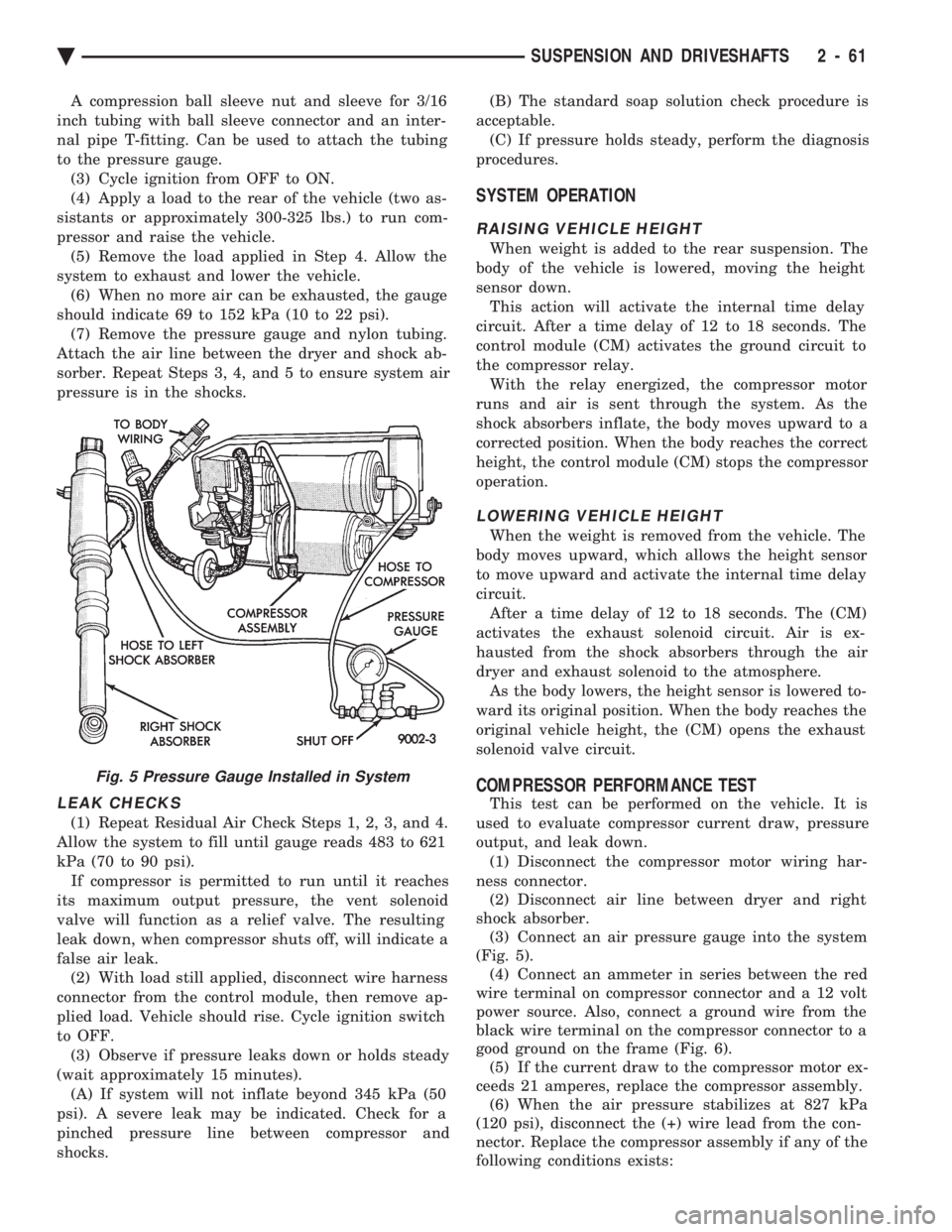
A compression ball sleeve nut and sleeve for 3/16
inch tubing with ball sleeve connector and an inter-
nal pipe T-fitting. Can be used to attach the tubing
to the pressure gauge. (3) Cycle ignition from OFF to ON.
(4) Apply a load to the rear of the vehicle (two as-
sistants or approximately 300-325 lbs.) to run com-
pressor and raise the vehicle. (5) Remove the load applied in Step 4. Allow the
system to exhaust and lower the vehicle. (6) When no more air can be exhausted, the gauge
should indicate 69 to 152 kPa (10 to 22 psi). (7) Remove the pressure gauge and nylon tubing.
Attach the air line between the dryer and shock ab-
sorber. Repeat Steps 3, 4, and 5 to ensure system air
pressure is in the shocks.
LEAK CHECKS
(1) Repeat Residual Air Check Steps 1, 2, 3, and 4.
Allow the system to fill until gauge reads 483 to 621
kPa (70 to 90 psi). If compressor is permitted to run until it reaches
its maximum output pressure, the vent solenoid
valve will function as a relief valve. The resulting
leak down, when compressor shuts off, will indicate a
false air leak. (2) With load still applied, disconnect wire harness
connector from the control module, then remove ap-
plied load. Vehicle should rise. Cycle ignition switch
to OFF. (3) Observe if pressure leaks down or holds steady
(wait approximately 15 minutes). (A) If system will not inflate beyond 345 kPa (50
psi). A severe leak may be indicated. Check for a
pinched pressure line between compressor and
shocks. (B) The standard soap solution check procedure is
acceptable. (C) If pressure holds steady, perform the diagnosis
procedures.
SYSTEM OPERATION
RAISING VEHICLE HEIGHT
When weight is added to the rear suspension. The
body of the vehicle is lowered, moving the height
sensor down. This action will activate the internal time delay
circuit. After a time delay of 12 to 18 seconds. The
control module (CM) activates the ground circuit to
the compressor relay. With the relay energized, the compressor motor
runs and air is sent through the system. As the
shock absorbers inflate, the body moves upward to a
corrected position. When the body reaches the correct
height, the control module (CM) stops the compressor
operation.
LOWERING VEHICLE HEIGHT
When the weight is removed from the vehicle. The
body moves upward, which allows the height sensor
to move upward and activate the internal time delay
circuit. After a time delay of 12 to 18 seconds. The (CM)
activates the exhaust solenoid circuit. Air is ex-
hausted from the shock absorbers through the air
dryer and exhaust solenoid to the atmosphere. As the body lowers, the height sensor is lowered to-
ward its original position. When the body reaches the
original vehicle height, the (CM) opens the exhaust
solenoid valve circuit.
COMPRESSOR PERFORMANCE TEST
This test can be performed on the vehicle. It is
used to evaluate compressor current draw, pressure
output, and leak down. (1) Disconnect the compressor motor wiring har-
ness connector. (2) Disconnect air line between dryer and right
shock absorber. (3) Connect an air pressure gauge into the system
(Fig. 5). (4) Connect an ammeter in series between the red
wire terminal on compressor connector and a 12 volt
power source. Also, connect a ground wire from the
black wire terminal on the compressor connector to a
good ground on the frame (Fig. 6). (5) If the current draw to the compressor motor ex-
ceeds 21 amperes, replace the compressor assembly. (6) When the air pressure stabilizes at 827 kPa
(120 psi), disconnect the (+) wire lead from the con-
nector. Replace the compressor assembly if any of the
following conditions exists:
Fig. 5 Pressure Gauge Installed in System
Ä SUSPENSION AND DRIVESHAFTS 2 - 61
Page 123 of 2438
REAR LEVELING DIAGNOSTIC PROCEDURES
SELF-DIAGNOSTICS
A self-diagnostic procedure is available for the ser-
vice technician to use to detect system malfunctions.
BEFORE DIAGNOSTICS TEST
Check the 20 amp fuse (position W40) and the 30
amp circuit breaker (position W5) to be assured they
are functional components. Check all connectors that link the system into the
main body wiring harness. These include compressor,
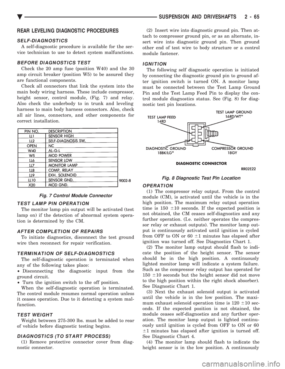
height sensor, control module, (Fig. 7) and relay.
Also check the underbody to in trunk and leveling
harness to main body harness connectors. Also, check
all air lines, connectors, and other components for
correct installation.
TEST LAMP PIN OPERATION
The monitor lamp pin output will be activated (test
lamp on) if the detection of abnormal system opera-
tion is determined by the CM.
AFTER COMPLETION OF REPAIRS
To initiate diagnostics, disconnect the test ground
wire then reconnect for repair verification.
TERMINATION OF SELF-DIAGNOSTICS
The self-diagnostic operation is terminated when
any of the following takes place:
² Disconnecting the diagnostic input from the
ground circuit.
² Turn the ignition switch to the off position.
When the self-diagnostic operation is terminated.
The control module resumes normal operation unless
it ceases operation. Due to it detecting a system mal-
function.
TEST WEIGHT
Weight between 275-300 lbs. must be added to rear
of vehicle before diagnostic testing begins.
DIAGNOSTICS (TO START PROCESS)
(1) Remove protective connector cover from diag-
nostic connector. (2) Insert wire into diagnostic ground pin. Then at-
tach to compressor ground pin, or as an alternate, in-
sert wire into diagnostic ground pin. Then ground
other end of test wire to body structure or a control
module fastener.
IGNITION
The following self diagnostic operation is initiated
by connecting the diagnostic ground pin to ground af-
ter ignition switch is turned ON. A monitor lamp
must be connected between the Test Lamp Ground
Pin and the Test Lamp Feed Pin to display the con-
trol module diagnostics status. See (Fig. 8) for diag-
nostic test pin locations.
OPERATION
(1) The compressor relay output. From the control
module (CM), is activated until the vehicle is in the
high position. The maximum relay output operation
time is 150 610 seconds. If the expected position is
not obtained, the CM ceases self-diagnostics and any
further operation. (I.e. neither operates the compres-
sor relay or exhaust outputs). The monitor lamp out-
put is continuously activated until ignition is cycled
from OFF to ON or 60 61 minutes has elapsed after
ignition was turned off. See Diagnostics Chart 1. (2) The monitor lamp output should flash to indi-
cate the position of the height sensor. The sensor
should be in the high position. A continuously
lighted monitor lamp will indicate a system failure.
Such as the compressor relay output has operated for
150 610 seconds but the height sensor did not move
to the high position within the right shock absorber).
See Diagnostic Chart 1. (3) Next the exhaust solenoid output is activated
until the vehicle is in the low position. The maxi-
mum exhaust solenoid operation time is 120 610 sec-
onds. If the expected position is not obtained, the
module ceases self-diagnostics and any further oper-
ation. The monitor lamp output is lighted continu-
ously until ignition is cycled from OFF to ON or 60
6 1 minutes has elapsed after ignition is turned off.
See Diagnostic Chart 4. (4) The monitor lamp should flash to indicate the
height sensor is in the low position. A continuouslyFig. 7 Control Module Connector
Fig. 8 Diagnostic Test Pin Location
Ä SUSPENSION AND DRIVESHAFTS 2 - 65
Page 132 of 2438
FRONT AND REAR AIR SPRINGS
The front and rear air springs are essentially pneu-
matic cylinders that replace the steel coil springs.
The air filled springs allow the vehicle suspension
height to be adjusted for all weight conditions. The air springs allow for the reduction of spring
rates to improve vehicle ride characteristics.
FRONT/REAR SPRING SOLENOIDS
The front and rear solenoids control air flow in and
out of the front and rear springs. The Air Suspension
Control Module (ASCM) opens the solenoids when
the system requires air to be added to or exhausted
from the air springs. The solenoids operate at a cur-
rent draw range of 0.6 to 1.5 amps.
HEIGHT SENSOR
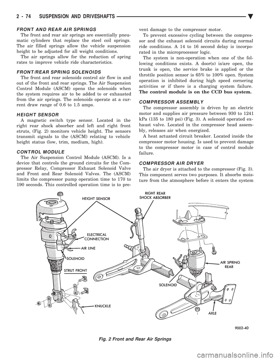
A magnetic switch type sensor. Located in the
right rear shock absorber and left and right front
struts, (Fig. 2) monitors vehicle height. The sensors
transmit signals to the (ASCM) relating to vehicle
height status (low, trim, medium, high).
CONTROL MODULE
The Air Suspension Control Module (ASCM). Is a
device that controls the ground circuits for the Com-
pressor Relay, Compressor Exhaust Solenoid Valve
and Front and Rear Solenoid Valves. The (ASCM)
limits the compressor pump operation time to 170 to
190 seconds. This controlled operation time is to pre- vent damage to the compressor motor.
To prevent excessive cycling between the compres-
sor and the exhaust solenoid circuits during normal
ride conditions. A 14 to 16 second delay is incorpo-
rated in the microprocessor logic. The system is non-operation when one of the fol-
lowing conditions exists. A door(s) is/are open, the
trunk is open, the service brake is applied or the
throttle position sensor is 65% to 100% open. System
operation is inhibited during high speed cornering
activities or if there is a charging system failure.
The control module is on the CCD bus system.
COMPRESSOR ASSEMBLY
The compressor assembly is driven by an electric
motor and supplies air pressure between 930 to 1241
kPa (135 to 180 psi) (Fig. 3). A solenoid operated ex-
haust valve. Located in the compressor head assem-
bly, releases air when energized. A heat actuated circuit breaker. Located inside the
compressor motor housing. Is used to prevent damage
to the compressor motor in case of control module
failure.
COMPRESSOR AIR DRYER
The air dryer is attached to the compressor (Fig. 3).
This component serves two purposes. It absorbs mois-
ture from the atmosphere before it enters the system
Fig. 2 Front and Rear Air Springs
2 - 74 SUSPENSION AND DRIVESHAFTS Ä
Page 151 of 2438
BRAKES
CONTENTS
page page
ANTI-LOCK BRAKE SYSTEMÐBENDIX ANTI-LOCK 10 AC/Y BODY ............. 72
ANTI-LOCK BRAKE SYSTEMÐBENDIX ANTI-LOCK 6 AA,AG,AJ,AP BODY ....... 113
BRAKE DISC (ROTOR) ................... 53
BRAKE SUPPORT ASSEMBLY ............. 25
FRONT DISC BRAKES ................... 31
GENERAL INFORMATION .................. 1
HYDRAULIC SYSTEM CONTROL VALVES . . . 26
KELSEY HAYES DOUBLE PIN FAMILY CALIPER ............................ 35 KELSEY HAYES DOUBLE PIN NON-FAMILY
CALIPER ............................ 38
MASTER CYLINDER ..................... 66
PARKING BRAKES ...................... 57
POWER BRAKES ....................... 68
REAR DISC BRAKES .................... 45
REAR WHEEL DRUM BRAKES ............ 18
SERVICE ADJUSTMENTS .................. 4
WHEEL BEARINGS ...................... 70
WHEEL CYLINDERS ..................... 23
GENERAL INFORMATION
Throughout this group, references may be made to
a particular vehicle by letter or number designation.
A chart showing the break down of these designa-
tions is included in the Introduction Section at the
front of this service manual. Standard brake equipment consists of:
² Double pin floating caliper disc front brakes.
² Rear automatic adjusting drum brakes.
² Differential valve with a brake warning switch.
² Master cylinder.
² Vacuum power booster.
² Double pin floating caliper rear disc brakes are
available on some models. The Bendix Anti-Lock 10 braking system, uses the
standard power brake system caliper assemblies,
braking discs, pedal assembly, brake lines and hoses.
The unique parts of the Bendix Anti-Lock 10 braking
system consists of the following components. Propor-
tioning valves, wheel speed sensors, tone wheels,
electronic control unit, modulator assembly and hy-
draulic assembly. These components replace the con-
ventional master cylinder and power booster. The
components will be described in detail in the Bendix
Anti-Lock 10 brake section in this group of the ser-
vice manual. The Bendix Anti-Lock 6 braking system, uses the
following standard brake system components. Master
cylinder, power booster, caliper assemblies, braking
discs, pedal assembly, brake lines and hoses. The
unique parts of the Bendix Anti-Lock 6 braking sys-
tem consists of the following components. Modulator
assembly, unique proportioning valves, wheel speed
sensors, tone wheels, and electronic control unit.
These components will be described in detail in the
Bendix Anti-Lock 6 brake section in this group of the
service manual. The front disc brake shoes have semi-metallic lin-
ings. The hydraulic brake system (Fig .123and4)is
diagonally split on both the Non-ABS and ABS brak-
ing system. With the left front and right rear brakes
on one hydraulic system and the right front and left
rear on the other. The Non-ABS and ABS brake system may use dif-
ferent types of brake line fittings and tubing flares.
The Non-ABS brake system uses double wall tubing
flares and fittings at all tubing joint locations. Some
ABS brake systems use both ISO style tubing flares
and double wall tubing flares and corresponding fit-
tings at different joint locations. See (Figs . 2 3 and 4)
for specific joint locations and type of tubing flare. The front disc brakes consist of two different types
of caliper assemblies. A double pin Kelsey-Hayes cal-
iper (family caliper) with a bolt-on adapter attached
to the steering knuckle. Or a double pin Kelsey-
Hayes caliper (non-family caliper) which mounts di-
rectly to rails on the steering knuckle. The non-
family caliper is only used on the AY Body
(Imperials).
CAUTION: Caliper pistons, boots and seals for the
different caliper assemblies used on the front and
rear disc brake assemblies are not interchangeable.
Misusage could result in a complete brake system
failure. Be sure that the parts are replaced with the
correct replacement parts, refer to the parts book
for the type and model year of the vehicle being
worked on.
The master cylinder is anodized, lightweight alu-
minum, with a bore size of 24.0mm, 21.0mm or 7/8
inch.
Ä BRAKES 5 - 1
Page 185 of 2438
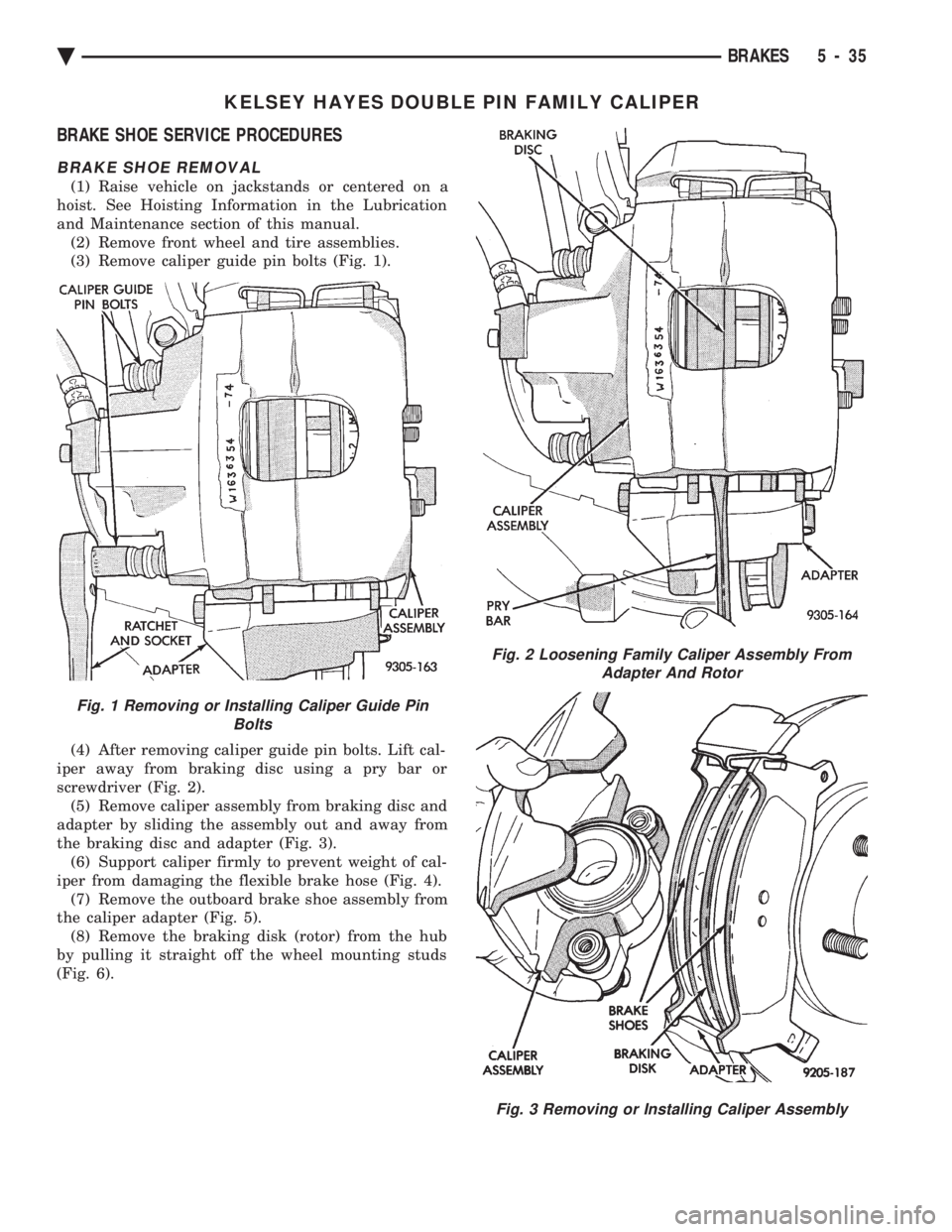
KELSEY HAYES DOUBLE PIN FAMILY CALIPER
BRAKE SHOE SERVICE PROCEDURES
BRAKE SHOE REMOVAL
(1) Raise vehicle on jackstands or centered on a
hoist. See Hoisting Information in the Lubrication
and Maintenance section of this manual. (2) Remove front wheel and tire assemblies.
(3) Remove caliper guide pin bolts (Fig. 1).
(4) After removing caliper guide pin bolts. Lift cal-
iper away from braking disc using a pry bar or
screwdriver (Fig. 2). (5) Remove caliper assembly from braking disc and
adapter by sliding the assembly out and away from
the braking disc and adapter (Fig. 3). (6) Support caliper firmly to prevent weight of cal-
iper from damaging the flexible brake hose (Fig. 4). (7) Remove the outboard brake shoe assembly from
the caliper adapter (Fig. 5). (8) Remove the braking disk (rotor) from the hub
by pulling it straight off the wheel mounting studs
(Fig. 6).
Fig. 1 Removing or Installing Caliper Guide Pin Bolts
Fig. 2 Loosening Family Caliper Assembly FromAdapter And Rotor
Fig. 3 Removing or Installing Caliper Assembly
Ä BRAKES 5 - 35
Page 188 of 2438
KELSEY HAYES DOUBLE PIN NON-FAMILY CALIPER INDEX
page page
Assembling Disc Brake Caliper .............. 42
Cleaning and Inspection of Brake Caliper ...... 41 Disc Brake Caliper Disassembly
............. 40
Service Procedures ....................... 38
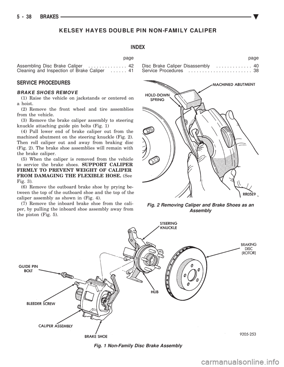
SERVICE PROCEDURES
BRAKE SHOES REMOVE
(1) Raise the vehicle on jackstands or centered on
a hoist. (2) Remove the front wheel and tire assemblies
from the vehicle. (3) Remove the brake caliper assembly to steering
knuckle attaching guide pin bolts (Fig. 1) (4) Pull lower end of brake caliper out from the
machined abutment on the steering knuckle (Fig. 2).
Then roll caliper out and away from braking disc
(Fig. 2). The brake shoe assemblies will remain with
the brake caliper. (5) When the caliper is removed from the vehicle
to service the brake shoes. SUPPORT CALIPER
FIRMLY TO PREVENT WEIGHT OF CALIPER
FROM DAMAGING THE FLEXIBLE HOSE. (See
Fig. 3). (6) Remove the outboard brake shoe by prying be-
tween the top of the outboard shoe and the top of the
caliper assembly as shown in (Fig. 4). (7) Remove the inboard brake shoe from the cali-
per, by pulling the inboard shoe assembly away from
the piston (Fig. 5).
Fig. 1 Non-Family Disc Brake Assembly
Fig. 2 Removing Caliper and Brake Shoes as an Assembly
5 - 38 BRAKES Ä
Page 408 of 2438
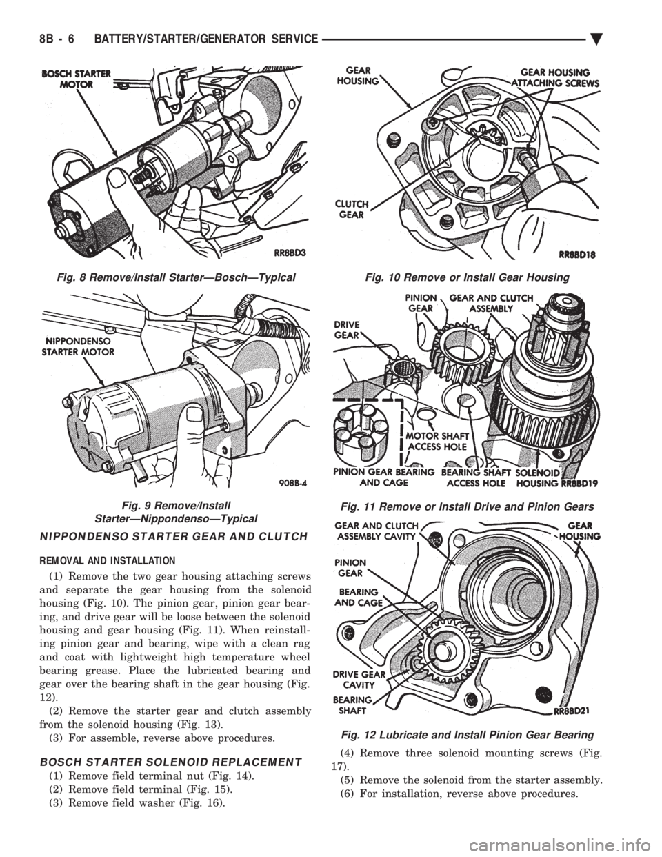
NIPPONDENSO STARTER GEAR AND CLUTCH
REMOVAL AND INSTALLATION (1) Remove the two gear housing attaching screws
and separate the gear housing from the solenoid
housing (Fig. 10). The pinion gear, pinion gear bear-
ing, and drive gear will be loose between the solenoid
housing and gear housing (Fig. 11). When reinstall-
ing pinion gear and bearing, wipe with a clean rag
and coat with lightweight high temperature wheel
bearing grease. Place the lubricated bearing and
gear over the bearing shaft in the gear housing (Fig.
12). (2) Remove the starter gear and clutch assembly
from the solenoid housing (Fig. 13). (3) For assemble, reverse above procedures.
BOSCH STARTER SOLENOID REPLACEMENT
(1) Remove field terminal nut (Fig. 14).
(2) Remove field terminal (Fig. 15).
(3) Remove field washer (Fig. 16). (4) Remove three solenoid mounting screws (Fig.
17). (5) Remove the solenoid from the starter assembly.
(6) For installation, reverse above procedures.
Fig. 8 Remove/Install StarterÐBoschÐTypical
Fig. 9 Remove/Install
StarterÐNippondensoÐTypical
Fig. 10 Remove or Install Gear Housing
Fig. 11 Remove or Install Drive and Pinion Gears
Fig. 12 Lubricate and Install Pinion Gear Bearing
8B - 6 BATTERY/STARTER/GENERATOR SERVICE Ä
Page 645 of 2438
EXTERIOR LAMP SWITCHES AND HEADLAMP ALIGNMENT INDEX
page page
Headlamp Adjustment Using Alignment Screen .... 3
Headlamp Alignment ....................... 3
Headlamp Alignment Preparation .............. 3 Headlamp Dimmer Switch
................... 3
Headlamp Switch .......................... 3
HEADLAMP SWITCH
Service procedures for the headlamp switch can be
found in Group 8E, Instrument Panel and Gauges. More
information can be found in Wiring Diagrams manual.
HEADLAMP DIMMER SWITCH
The headlamp dimmer switch is incorporated into
the turn signal switch. Proper procedures can be found
in Group 8J, Turn Signal and Flashers. More informa-
tion can be found in Group 8W, Wiring Diagrams.
HEADLAMP ALIGNMENT
Headlamps can be aligned using the screen method
provided in this section. Alignment Tool C4466-A or
equivalent can also be used. Refer to instructions
provided with the tool for proper procedures. The
preferred headlamp alignment setting is 0 for the
left/right adjustment and 0 for the up/down ad-
justment.
HEADLAMP ALIGNMENT PREPARATION
(1) Verify headlamp dimmer switch and high beam
indicator operation. (2) Inspect and correct damaged or defective compo-
nents that could interfere with proper headlamp align-
ment. (3) Verify proper tire inflation.
(4) Clean headlamp lenses.
(5) Verify that luggage area is not heavily loaded.
(6) Fuel tank should be FULL. Add 2.94 kg (6.5 lbs.)
of weight over the fuel tank for each estimated gallon of
missing fuel.
HEADLAMP ADJUSTMENT USING ALIGNMENT
SCREEN
ALIGNMENT SCREEN PREPARATION (FIG. 1 AND 2)
(1) Position vehicle on a level surface perpendicular
to a flat wall 7.62 meters (25 ft) away from front of
headlamp lens. (2) If necessary, tape a line on the floor 7.62 meters
(25 ft) away from and parallel to the wall.
(3) From the floor up 1.27 meters (5 ft), tape a line on
the wall at the centerline of the vehicle. Sight along the
centerline of the vehicle (from rear of vehicle forward) to
verify accuracy of the line placement.
(4) Rock vehicle side-to-side three times to allow
suspension to stabilize. (5) Jounce front suspension three times by pushing
downward on front bumper and releasing. (6) Measure the distance from the center of head-
lamp lens to the floor. Transfer measurement to the
alignment screen (with tape). Use this line for up/down
adjustment reference. (7) Measure distance from the centerline of the ve-
hicle to the center of each headlamp being aligned.
Transfer measurements to screen (with tape) to each
side of vehicle centerline. Use these lines for left/right
adjustment reference.
HEADLAMP ADJUSTMENT (FIG. 3, 4, 5, 6 OR 7)
A properly aimed low beam headlamp will project the
top edge of low beam hot spot on the alignment screen
from 50 mm (2 in.) above to 50 mm (2 in.) below the
headlamp centerline. The side-to-side left edge of low
beam hot spot should be from 50 mm (2 in.) left to
50mm (2 in.) right of headlamp centerline (Fig. 1). The
preferred headlamp alignment is 0 for the
up/down adjustment and 0 for the left/right ad-
justment. The high beams on a vehicle with aero
headlamps cannot be aligned. The high beam pattern
should be correct when the low beams are aligned
properly. To adjust headlamp alignment, rotate alignment
screws to achieve the specified low beam hot spot
pattern.
CAUTION: Do not cover an illuminated headlamp for
more then 15 seconds. Lamp will overheat and burn
or melt cover.
To adjust headlamps, rotate alignment screws to
achieve the specified high intensity pattern (Fig. 1 or
2).
FOG LAMP ALIGNMENT (FIG. 8)
Prepare an alignment screen. Refer to Alignment
Screen Preparation paragraph in this section. A prop-
erly aligned fog lamp will project a pattern on the
alignment screen 100 mm (4 in.) below the fog lamp
centerline and straight ahead.
Ä LAMPS 8L - 3
Page 1569 of 2438
scuffing, scoring or scratches. Usually a few strokes
will clean up a bore and maintain the required limits.(2) Deglazing of the cylinder walls may be done
using a cylinder surfacing hone, Tool C-3501, equipped
with 280 grit stones (C-3501-3810) if the cylinder bore
is straight and round. 20-60 strokes depending on the
bore condition will be sufficient to provide a satisfac-
tory surface. Inspect cylinder walls after each 20
strokes. Using a light honing oil available from major
oil distributors. Do not use engine or transmission
oil, mineral spirits or kerosene. (3) Honing should be done by moving the hone up
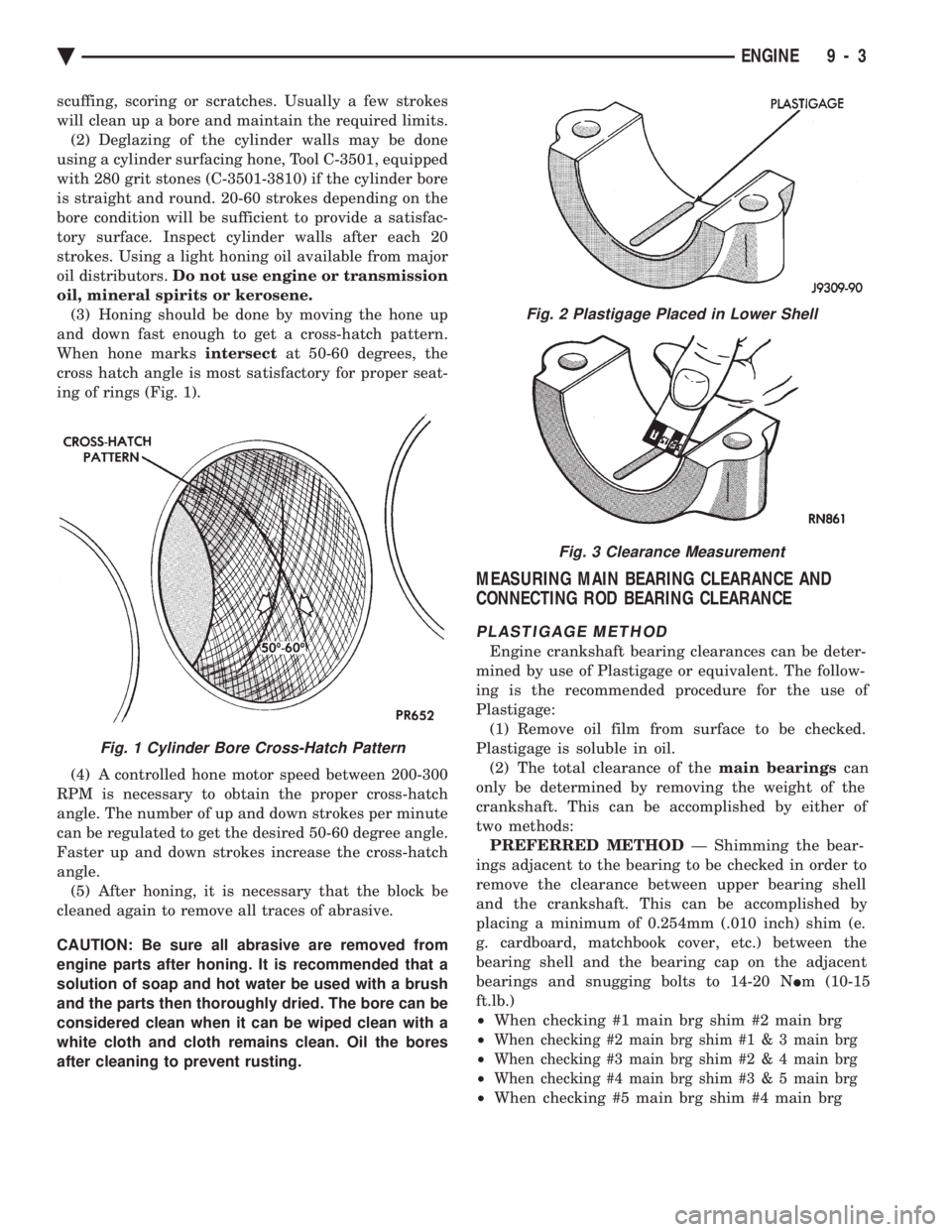
and down fast enough to get a cross-hatch pattern.
When hone marks intersectat 50-60 degrees, the
cross hatch angle is most satisfactory for proper seat-
ing of rings (Fig. 1).
(4) A controlled hone motor speed between 200-300
RPM is necessary to obtain the proper cross-hatch
angle. The number of up and down strokes per minute
can be regulated to get the desired 50-60 degree angle.
Faster up and down strokes increase the cross-hatch
angle. (5) After honing, it is necessary that the block be
cleaned again to remove all traces of abrasive.
CAUTION: Be sure all abrasive are removed from
engine parts after honing. It is recommended that a
solution of soap and hot water be used with a brush
and the parts then thoroughly dried. The bore can be
considered clean when it can be wiped clean with a
white cloth and cloth remains clean. Oil the bores
after cleaning to prevent rusting.
MEASURING MAIN BEARING CLEARANCE AND
CONNECTING ROD BEARING CLEARANCE
PLASTIGAGE METHOD
Engine crankshaft bearing clearances can be deter-
mined by use of Plastigage or equivalent. The follow-
ing is the recommended procedure for the use of
Plastigage: (1) Remove oil film from surface to be checked.
Plastigage is soluble in oil. (2) The total clearance of the main bearingscan
only be determined by removing the weight of the
crankshaft. This can be accomplished by either of
two methods: PREFERRED METHOD Ð Shimming the bear-
ings adjacent to the bearing to be checked in order to
remove the clearance between upper bearing shell
and the crankshaft. This can be accomplished by
placing a minimum of 0.254mm (.010 inch) shim (e.
g. cardboard, matchbook cover, etc.) between the
bearing shell and the bearing cap on the adjacent
bearings and snugging bolts to 14-20 N Im (10-15
ft.lb.)
² When checking #1 main brg shim #2 main brg
²
When checking #2 main brg shim # 1 & 3 main brg
²When checking #3 main brg shim #2 & 4 main brg
²When checking #4 main brg shim #3 & 5 main brg
²When checking #5 main brg shim #4 main brg
Fig. 2 Plastigage Placed in Lower Shell
Fig. 3 Clearance Measurement
Fig. 1 Cylinder Bore Cross-Hatch Pattern
Ä ENGINE 9 - 3
Page 1570 of 2438
REMOVE ALL SHIMS BEFORE REASSEM-
BLING ENGINE ALTERNATIVE METHOD Ð With the weight of
the crankshaft being supported by a jack under the
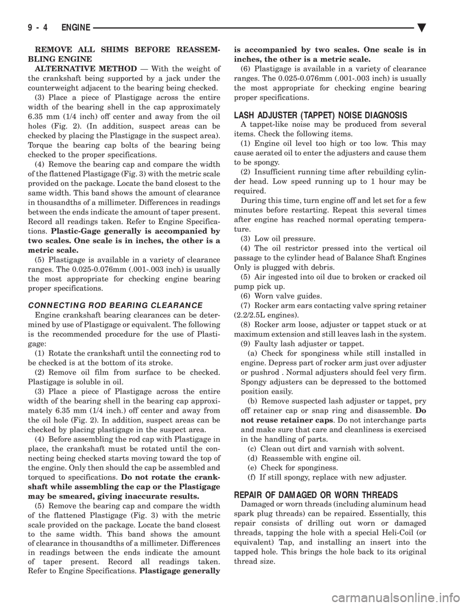
counterweight adjacent to the bearing being checked. (3) Place a piece of Plastigage across the entire
width of the bearing shell in the cap approximately
6.35 mm (1/4 inch) off center and away from the oil
holes (Fig. 2). (In addition, suspect areas can be
checked by placing the Plastigage in the suspect area).
Torque the bearing cap bolts of the bearing being
checked to the proper specifications. (4) Remove the bearing cap and compare the width
of the flattened Plastigage (Fig. 3) with the metric scale
provided on the package. Locate the band closest to the
same width. This band shows the amount of clearance
in thousandths of a millimeter. Differences in readings
between the ends indicate the amount of taper present.
Record all readings taken. Refer to Engine Specifica-
tions. Plastic-Gage generally is accompanied by
two scales. One scale is in inches, the other is a
metric scale. (5) Plastigage is available in a variety of clearance
ranges. The 0.025-0.076mm (.001-.003 inch) is usually
the most appropriate for checking engine bearing
proper specifications.
CONNECTING ROD BEARING CLEARANCE
Engine crankshaft bearing clearances can be deter-
mined by use of Plastigage or equivalent. The following
is the recommended procedure for the use of Plasti-
gage: (1) Rotate the crankshaft until the connecting rod to
be checked is at the bottom of its stroke. (2) Remove oil film from surface to be checked.
Plastigage is soluble in oil. (3) Place a piece of Plastigage across the entire
width of the bearing shell in the bearing cap approxi-
mately 6.35 mm (1/4 inch.) off center and away from
the oil hole (Fig. 2). In addition, suspect areas can be
checked by placing plastigage in the suspect area. (4) Before assembling the rod cap with Plastigage in
place, the crankshaft must be rotated until the con-
necting being checked starts moving toward the top of
the engine. Only then should the cap be assembled and
torqued to specifications. Do not rotate the crank-
shaft while assembling the cap or the Plastigage
may be smeared, giving inaccurate results. (5) Remove the bearing cap and compare the width
of the flattened Plastigage (Fig. 3) with the metric
scale provided on the package. Locate the band closest
to the same width. This band shows the amount
of clearance in thousandths of a millimeter. Differences
in readings between the ends indicate the amount
of taper present. Record all readings taken.
Refer to Engine Specifications. Plastigage generally is accompanied by two scales. One scale is in
inches, the other is a metric scale. (6) Plastigage is available in a variety of clearance
ranges. The 0.025-0.076mm (.001-.003 inch) is usually
the most appropriate for checking engine bearing
proper specifications.
LASH ADJUSTER (TAPPET) NOISE DIAGNOSIS
A tappet-like noise may be produced from several
items. Check the following items. (1) Engine oil level too high or too low. This may
cause aerated oil to enter the adjusters and cause them
to be spongy. (2) Insufficient running time after rebuilding cylin-
der head. Low speed running up to 1 hour may be
required. During this time, turn engine off and let set for a few
minutes before restarting. Repeat this several times
after engine has reached normal operating tempera-
ture. (3) Low oil pressure.
(4) The oil restrictor pressed into the vertical oil
passage to the cylinder head of Balance Shaft Engines
Only is plugged with debris. (5) Air ingested into oil due to broken or cracked oil
pump pick up. (6) Worn valve guides.
(7) Rocker arm ears contacting valve spring retainer
(2.2/2.5L engines). (8) Rocker arm loose, adjuster or tappet stuck or at
maximum extension and still leaves lash in the system. (9) Faulty lash adjuster or tappet.(a) Check for sponginess while still installed in
engine. Depress part of rocker arm just over adjuster
or pushrod . Normal adjusters should feel very firm.
Spongy adjusters can be depressed to the bottomed
position easily. (b) Remove suspected lash adjuster or tappet, pry
off retainer cap or snap ring and disassemble. Do
not reuse retainer caps . Do not interchange parts
and make sure that care and cleanliness is exercised
in the handling of parts. (c) Clean out dirt and varnish with solvent.
(d) Reassemble with engine oil.
(e) Check for sponginess.
(f) If still spongy, replace with new adjuster.
REPAIR OF DAMAGED OR WORN THREADS
Damaged or worn threads (including aluminum head
spark plug threads) can be repaired. Essentially, this
repair consists of drilling out worn or damaged
threads, tapping the hole with a special Heli-Coil (or
equivalent) Tap, and installing an insert into the
tapped hole. This brings the hole back to its original
thread size.
9 - 4 ENGINE Ä