CHEVROLET EXPRESS PASSANGER 2007 1.G Owners Manual
Manufacturer: CHEVROLET, Model Year: 2007, Model line: EXPRESS PASSANGER, Model: CHEVROLET EXPRESS PASSANGER 2007 1.GPages: 458, PDF Size: 2.62 MB
Page 331 of 458
Notice:Ignoring these steps could result in
costly damage to your vehicle that would
not be covered by your warranty.
Trying to start your vehicle by pushing or
pulling it will not work, and it could damage
your vehicle.
1. Check the other vehicle. It must have a
12-volt battery with a negative ground system.
Notice:If the other vehicle’s system is not
a 12-volt system with a negative ground, both
vehicles can be damaged. Only use vehicles
with 12-volt systems with negative grounds to
jump start your vehicle.
2. Get the vehicles close enough so the jumper
cables can reach, but be sure the vehicles are
not touching each other. If they are, it could
cause a ground connection you do not
want. You would not be able to start your
vehicle, and the bad grounding could damage
the electrical systems.To avoid the possibility of the vehicles rolling,
set the parking brake firmly on both vehicles
involved in the jump start procedure. Put
an automatic transmission in PARK (P) or a
manual transmission in NEUTRAL before
setting the parking brake.
Notice:If you leave your radio or other
accessories on during the jump starting
procedure, they could be damaged. The
repairs would not be covered by your
warranty. Always turn off your radio and
other accessories when jump starting
your vehicle.
3. Turn off the ignition on both vehicles.
Unplug unnecessary accessories plugged
into the cigarette lighter or the accessory
power outlet. Turn off the radio and all
lamps that are not needed. This will avoid
sparks and help save both batteries.
And it could save the radio!
331
Page 332 of 458
4. Open the hoods and locate the positive (+)
and negative (−) terminal locations of the
other vehicle.
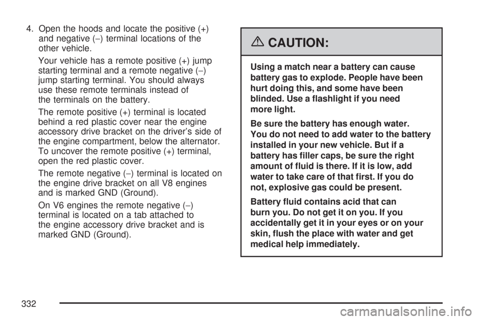
Your vehicle has a remote positive (+) jump
starting terminal and a remote negative (−)
jump starting terminal. You should always
use these remote terminals instead of
the terminals on the battery.
The remote positive (+) terminal is located
behind a red plastic cover near the engine
accessory drive bracket on the driver’s side of
the engine compartment, below the alternator.
To uncover the remote positive (+) terminal,
open the red plastic cover.
The remote negative (−) terminal is located on
the engine drive bracket on all V8 engines
and is marked GND (Ground).
On V6 engines the remote negative (−)
terminal is located on a tab attached to
the engine accessory drive bracket and is
marked GND (Ground).
{CAUTION:
Using a match near a battery can cause
battery gas to explode. People have been
hurt doing this, and some have been
blinded. Use a �ashlight if you need
more light.
Be sure the battery has enough water.
You do not need to add water to the battery
installed in your new vehicle. But if a
battery has �ller caps, be sure the right
amount of �uid is there. If it is low, add
water to take care of that �rst. If you do
not, explosive gas could be present.
Battery �uid contains acid that can
burn you. Do not get it on you. If you
accidentally get it in your eyes or on your
skin, �ush the place with water and get
medical help immediately.
332
Page 333 of 458
{CAUTION:
Fans or other moving engine parts can
injure you badly. Keep your hands away
from moving parts once the engine is
running.
5. Check that the jumper cables do not have
loose or missing insulation. If they do, you
could get a shock. The vehicles could
be damaged too.
Before you connect the cables, here are some
basic things you should know. Positive (+)
will go to positive (+) or to a remote
positive (+) terminal if the vehicle has one.
Negative (−) will go to a heavy, unpainted
metal engine part or to a remote negative (−)
terminal if the vehicle has one.
Do not connect positive (+) to negative (−)
or you will get a short that would damage
the battery and maybe other parts too.
And do not connect the negative (−) cable
to the negative (−) terminal on the dead
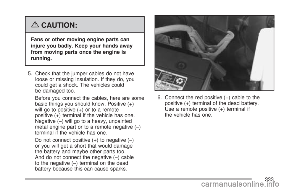
battery because this can cause sparks.6. Connect the red positive (+) cable to the
positive (+) terminal of the dead battery.
Use a remote positive (+) terminal if
the vehicle has one.
333
Page 334 of 458
7. Do not let the other end touch metal.
Connect it to the positive (+) terminal of the
good battery. Use a remote positive (+)
terminal if the vehicle has one.
8. Now connect the black negative (−) cable to
the negative (−) terminal of the good battery.
Use a remote negative (−) terminal if the
vehicle has one.
Do not let the other end touch anything until the
next step. The other end of the negative (−)
cable does not go to the dead battery. It goes to
a heavy, unpainted metal engine part or to a
remote negative (−) terminal on the vehicle
with the dead battery.9. Connect the other end of the negative (−)
cable to the negative (−) terminal location
on the vehicle with the dead battery.
Your vehicle has a remote negative (−)
terminal for this purpose. It is marked GND.
10. Now start the vehicle with the good battery
and run the engine for a while.
11. Try to start the vehicle that had the dead
battery. If it will not start after a few tries,
it probably needs service.
Notice:If the jumper cables are connected or
removed in the wrong order, electrical shorting
may occur and damage the vehicle. The repairs
would not be covered by your warranty. Always
connect and remove the jumper cables in the
correct order, making sure that the cables do
not touch each other or other metal.
334
Page 335 of 458
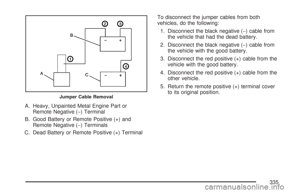
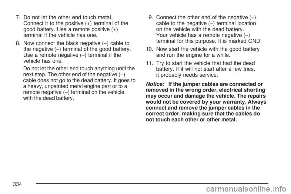
A. Heavy, Unpainted Metal Engine Part or
Remote Negative (−) Terminal
B. Good Battery or Remote Positive (+) and
Remote Negative (−) Terminals
C. Dead Battery or Remote Positive (+) TerminalTo disconnect the jumper cables from both
vehicles, do the following:
1. Disconnect the black negative (−) cable from
the vehicle that had the dead battery.
2. Disconnect the black negative (−) cable from
the vehicle with the good battery.
3. Disconnect the red positive (+) cable from the
vehicle with the good battery.
4. Disconnect the red positive (+) cable from the
other vehicle.
5. Return the remote positive (+) terminal cover
to its original position.
Jumper Cable Removal
335
Page 336 of 458
All-Wheel Drive
Lubricant checks in this section also apply to
these vehicles. However, there are two additional
systems that need lubrication.
Transfer Case
When to Check Lubricant
Refer to the Maintenance Schedule to determine
how often to check the lubricant. SeeScheduled
Maintenance (Gasoline Engine) on page 405.
How to Check Lubricant
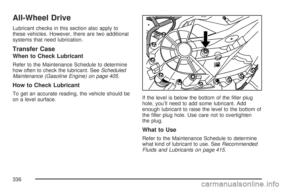
To get an accurate reading, the vehicle should be
on a level surface.If the level is below the bottom of the filler plug
hole, you’ll need to add some lubricant. Add
enough lubricant to raise the level to the bottom of
the filler plug hole. Use care not to overtighten
the plug.
What to Use
Refer to the Maintenance Schedule to determine
what kind of lubricant to use. SeeRecommended
Fluids and Lubricants on page 415.
336
Page 337 of 458
Rear Axle
When to Check Lubricant
Refer to the Maintenance Schedule to determine
how often to check the lubricant. SeeScheduled
Maintenance (Gasoline Engine) on page 405.
How to Check Lubricant
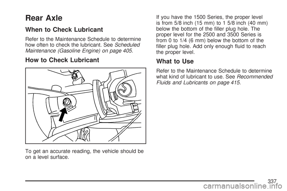
To get an accurate reading, the vehicle should be
on a level surface.If you have the 1500 Series, the proper level
is from 5/8 inch (15 mm) to 1 5/8 inch (40 mm)
below the bottom of the filler plug hole. The
proper level for the 2500 and 3500 Series is
from 0 to 1/4 (6 mm) below the bottom of the
filler plug hole. Add only enough fluid to reach
the proper level.
What to Use
Refer to the Maintenance Schedule to determine
what kind of lubricant to use. SeeRecommended
Fluids and Lubricants on page 415.
337
Page 338 of 458
Front Axle
When to Check and Change Lubricant
Refer to the Maintenance Schedule to determine
how often to check the lubricant and when
to change it. SeeScheduled Maintenance
(Gasoline Engine) on page 405.
How to Check Lubricant
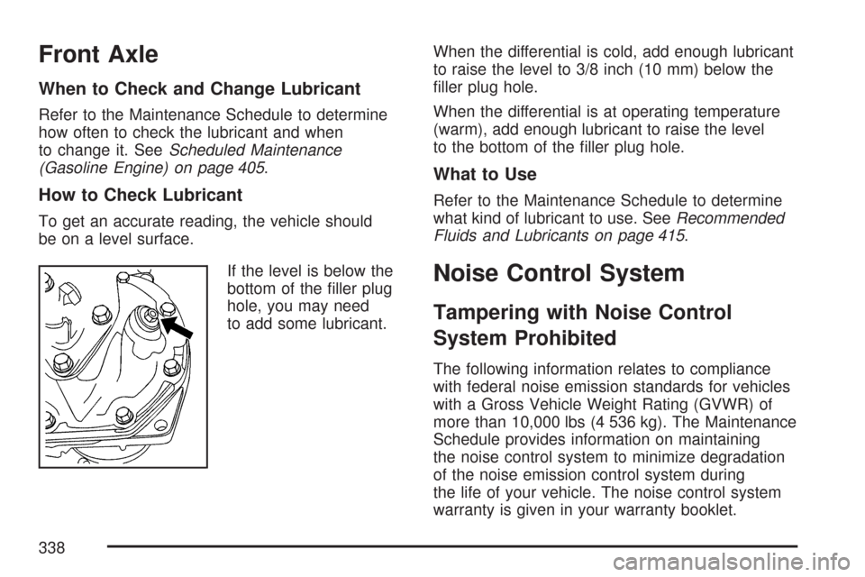
To get an accurate reading, the vehicle should
be on a level surface.
If the level is below the
bottom of the filler plug
hole, you may need
to add some lubricant.When the differential is cold, add enough lubricant
to raise the level to 3/8 inch (10 mm) below the
filler plug hole.
When the differential is at operating temperature
(warm), add enough lubricant to raise the level
to the bottom of the filler plug hole.
What to Use
Refer to the Maintenance Schedule to determine
what kind of lubricant to use. SeeRecommended
Fluids and Lubricants on page 415.
Noise Control System
Tampering with Noise Control
System Prohibited
The following information relates to compliance
with federal noise emission standards for vehicles
with a Gross Vehicle Weight Rating (GVWR) of
more than 10,000 lbs (4 536 kg). The Maintenance
Schedule provides information on maintaining
the noise control system to minimize degradation
of the noise emission control system during
the life of your vehicle. The noise control system
warranty is given in your warranty booklet.
338
Page 339 of 458
These standards apply only to vehicles sold in
the United States.
Federal law prohibits the following acts or the
causing thereof:
1. The removal or rendering inoperative by
any person, other than for purposes of
maintenance, repair or replacement, of any
device or element of design incorporated into
any new vehicle for the purpose of noise
control, prior to its sale or delivery to
the ultimate purchaser or while it is in use; or
2. The use of the vehicle after such device or
element of design has been removed or
rendered inoperative by any person.
Among those acts presumed to constitute
tampering are the acts listed below.
Insulation:
•
Removal of the noise shields or any
underhood insulation.
Engine:
•
Removal or rendering engine speed governor,
if the vehicle has one, inoperative so as to
allow engine speed to exceed manufacturer
specifications.
Fan and Drive:
•
Removal of fan clutch, if the vehicle has one,
or rendering clutch inoperative.
•Removal of the fan shroud, if the vehicle
has one.
Air Intake:
•
Removal of the air cleaner silencer.
•Modification of the air cleaner.
Exhaust:
•
Removal of the muffler and/or resonator.
•Removal of the exhaust pipes and exhaust
pipe clamps.
Fuel Operated Heater (FOH) — Diesel
Engine:
•
Removal of the muffler.
339
Page 340 of 458
Bulb Replacement
For the proper type of replacement bulbs, see
Replacement Bulbs on page 344.
For any bulb changing procedure not listed in
this section, contact your dealer.
Halogen Bulbs
{CAUTION:
Halogen bulbs have pressurized gas
inside and can burst if you drop or
scratch the bulb. You or others could be
injured. Be sure to read and follow the
instructions on the bulb package.
Headlamps
To remove the headlamp assembly from the
vehicle and access the bulbs:
1. Open the hood. SeeHood Release on
page 300for more information.
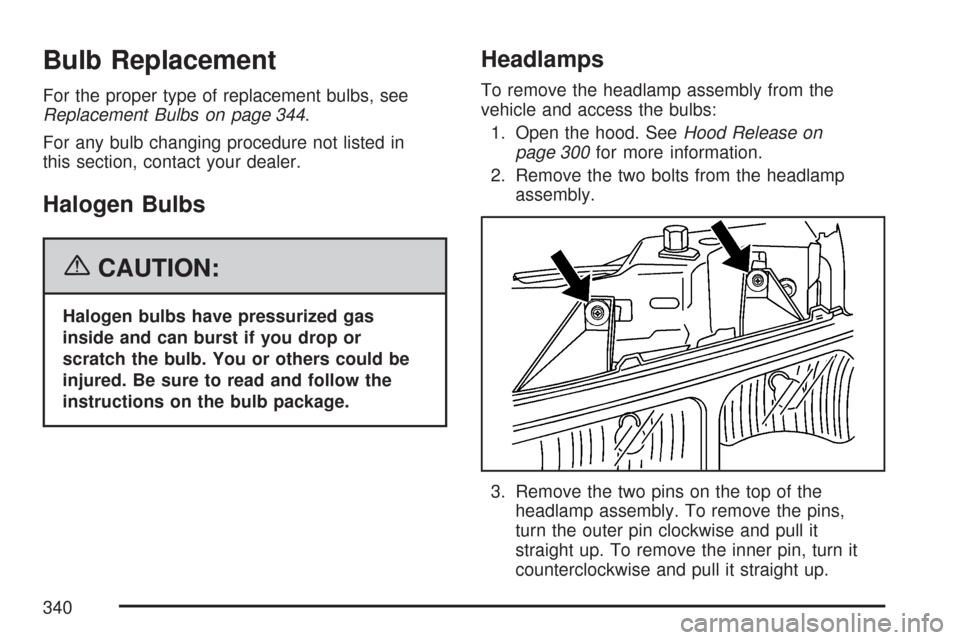
2. Remove the two bolts from the headlamp
assembly.
3. Remove the two pins on the top of the
headlamp assembly. To remove the pins,
turn the outer pin clockwise and pull it
straight up. To remove the inner pin, turn it
counterclockwise and pull it straight up.
340