heating CHEVROLET KODIAK 2009 Owners Manual
[x] Cancel search | Manufacturer: CHEVROLET, Model Year: 2009, Model line: KODIAK, Model: CHEVROLET KODIAK 2009Pages: 376, PDF Size: 5.39 MB
Page 76 of 376
Engine Starter Over-Crank
Protection
The vehicle may have an engine starter over-crank
protection system. If the starter motor overheats and
shuts off due to over-cranking, the motor must cool down
before it will reset and allow starter operation. It can take
up to six minutes before the starter will work again.
Starting the Gasoline Engine
The 8th digit of the Vehicle Identification Number (VIN)
shows the code letter for the engine. Use this number
to verify the type of engine in the vehicle. SeeVehicle
Identification Number (VIN) on page 5-94. Follow
the proper steps to start the engine.
To start a diesel engine, seeStarting the Diesel Engine
on page 2-14.
Automatic Transmission
Set the parking brake and move the shifter to N (Neutral)
or P (Park), if so equipped. The engine will not start in
any other position.
Manual Transmission
Set the parking brake, shift to N (Neutral) and hold the
clutch pedal to the floor while starting the engine.
Starter Motor Operation
•The starter motor will disengage if you release the
key or the engine reaches a predetermined engine
speed.
•To prevent overheating, the starter motor will
disengage after continuously operating for
15 seconds. You must release the key from the
start position to re-engage the starter.
•The starter motor will not engage if the engine is
already running.
•The starter motor will disengage if, after
two seconds, the starter pinion gear does not
engage the flywheel or there is no engine rpm
signal from the engine speed sensor.
2-12
Page 78 of 376
Moisture will condense in a fuel tank that is almost
empty if the engine has not run for a while, even just
overnight under some conditions. So, it is always best to
refuel the vehicle at the end of each run.
Starting the Diesel Engine
The vehicle’s diesel engine starts differently than a
gasoline engine. Read the following pages to learn how
to start, restart, warm-up, and stop the diesel engine.
The information applies to Caterpillar
®Diesel Engine,
6.6L DURAMAX®Diesel Engine, Isuzu 6H Diesel
Engine, unless otherwise noted.
If you have a Caterpillar
®Diesel Engine, also refer to
the Caterpillar®Diesel Engine Operation & Maintenance
Manual for the starting procedure.
Automatic Transmission
Move the shifter to P (Park) or N (Neutral). The engine
will not start in any other position. To restart the
engine when the vehicle is already moving, use
N (Neutral) only.
Notice:Do not try to shift to P (Park) if the
vehicle is moving. If you do, you could damage
the transmission. Shift to P (Park) only when
the vehicle is stopped.
Manual Transmission
Move the shift lever to N (Neutral) and hold the clutch
pedal to the floor while starting the engine. The vehicle
will not start if the clutch pedal is not all the way down.
Starting the Engine
1. Turn your ignition key to ON/RUN.
Observe the wait to start light. SeeWait to Start
Light on page 3-35. This light may not come
on if the engine is hot.
If you have a Caterpillar
®diesel engine, see your
Caterpillar®Diesel Engine Operation & Maintenance
Manual for proper wait to start light operation.
2. As soon as the wait to start light goes off,
immediately turn the ignition key to START.
When the engine starts, let go of the key.
If the vehicle is equipped with a DURAMAX
®
6600 Diesel Engine, it has a fast warm-up glow
plug system. The wait to start light will illuminate for
a much shorter time than most diesel engines,
due to the rapid heating of the glow plugs.
Notice:Holding the key in START for longer than
15 seconds at a time will cause the battery to
be drained much sooner. And the excessive heat
can damage the starter motor.
2-14
Page 88 of 376
During this warm-up period, check the warning lights
and gages:
•If oil pressure does not begin to rise within
15 seconds of starting, stop the engine and find the
cause. SeeOil Pressure Gage on page 3-38for
more information.
•If the engine coolant temperature gage needle goes
into the hot area on the gage, stop the engine and
find the cause of the overheating. SeeEngine
Coolant Temperature Gage on page 3-34for more
information.
•If you have air brakes, the dual-needle air pressure
gage should read at least 115 psi (790 kPa) for both
service systems before you try to move the vehicle.
When air pressure is below 60 psi (420 kPa), the
LOW AIR light will come on and you will hear a
tone alarm. SeeBrake System Warning Light on
page 3-31for more information. If the pressure does
not build up or drops during warm-up, stop the
engine and find the cause before you try to move the
vehicle. Recommended air pressure before driving is
120 psi (830 kPa). SeeAir Pressure Gage on
page 3-47for more information.
•The charging system light should come on when the
ignition key is turned to ON/RUN or START and
should go out when the engine is running above idle.
If the light does not go out or comes back on during
normal engine operation, have the charging system
checked right away. (This light tells you if the
generator is not charging; it does not reflect the
condition of the battery.) SeeCharging System Light
on page 3-29for more information.
•The voltmeter charge indicator gage tells you the
condition of the battery’s charge. The gage should be
in the center area during engine operation. The red
area on the left indicates an undercharge condition;
the red area on the right indicates an overcharge.
If the gage is in either red area, have the battery and
charging system checked right away. SeeVoltmeter
Gage on page 3-30for more information.
Notice:Do not allow the engine to operate at low
idle for more than five minutes. This can cause low
engine operating temperatures which can affect
engine operation and reduce engine life. Engine idle
speed should be increased to 1200 rpm whenever
extended idle is required. Once started, the engine
should be placed under load to allow the engine
coolant temperature to reach 150°F (66°C) before
shutting off the engine.
2-24
Page 119 of 376
Instrument Panel Overview...............................3-4
Hazard Warning Flashers................................3-6
Horn .............................................................3-6
Tilt Wheel.....................................................3-6
Turn Signal/Multifunction Lever.........................3-7
Turn and Lane-Change Signals........................3-7
Headlamp High/Low-Beam Changer..................3-8
Windshield Wipers..........................................3-8
Windshield Washer.........................................3-9
Cruise Control..............................................3-10
Exterior Lamps.............................................3-14
Headlamps on Reminder................................3-14
Daytime Running Lamps (DRL).......................3-15
Marker Lamps..............................................3-16
Instrument Panel Brightness...........................3-16
Dome Lamps ...............................................3-16
Entry Lighting...............................................3-17
Reading Lamps............................................3-17
Instrument Panel Switchbank..........................3-18
Accessory Power Outlet(s).............................3-19
Ashtray(s) and Cigarette Lighter......................3-19Climate Controls............................................3-20
Climate Control System.................................3-20
Outlet Adjustment.........................................3-22
Rear Heating System....................................3-23
Warning Lights, Gages, and Indicators............3-23
Instrument Panel Cluster................................3-24
Speedometer and Odometer...........................3-25
Trip Odometer..............................................3-25
Tachometer.................................................3-25
Engine Speed Limiter....................................3-25
Safety Belt Reminders...................................3-26
Airbag Readiness Light..................................3-27
Airbag Off Light............................................3-28
Charging System Light
..................................3-29
Voltmeter Gage............................................3-30
Service Transmission Warning Light................3-30
Range Inhibit Warning Indicator......................3-31
Brake System Warning Light..........................3-31
Antilock Brake System (ABS) Warning Light........3-33
Trailer Antilock Brake System Warning Light.......3-34
Engine Coolant Temperature Gage..................3-34
Section 3 Instrument Panel
3-1
Page 137 of 376
Accessory Power Outlet(s)
Accessory power outlets let you plug in auxiliary
electrical equipment, such as a cellular telephone.
The accessory power outlet is located on the
passenger’s side of the instrument panel.
To use an outlet, pull the cover down. When not using
it, always cover the outlet with the protective cap.
This circuit is protected by a fuse and has a maximum
current level.
Notice:Leaving electrical equipment on for
extended periods will drain the battery. Always turn
off electrical equipment when not in use and do not
plug in equipment that exceeds the maximum
amperage rating.
Certain electrical accessories may not be compatible
with the accessory power outlet and could result
in blown vehicle or adapter fuses. If you experience a
problem, see your dealer/retailer for additional
information on accessory power outlets.
Notice:Adding any electrical equipment to the
vehicle can damage it or keep other components
from working as they should. The repairs would not
be covered by the vehicle warranty. Do not use
equipment exceeding maximum amperage rating of
20 amperes. Check with your dealer/retailer before
adding electrical equipment.When adding electrical equipment, be sure to follow the
proper installation instructions included with the
equipment.
Notice:Improper use of the power outlet can cause
damage not covered by the warranty. Do not hang
any type of accessory or accessory bracket from the
plug because the power outlets are designed for
accessory power plugs only.
Ashtray(s) and Cigarette Lighter
For vehicles with an ashtray and a cigarette lighter, they
are located in the center floor console. To open the
removable ashtray, flip open the top.
Notice:If papers, pins, or other flammable items
are put in the ashtray, hot cigarettes or other
smoking materials could ignite them and possibly
damage the vehicle. Never put flammable items
in the ashtray.
To use the cigarette lighter, push it in all the way and let
it go. When it’s ready, it will pop back out by itself.
Notice:Holding a cigarette lighter in while it
is heating does not let the lighter back away from
the heating element when it is hot. Damage from
overheating can occur to the lighter or heating
element, or a fuse could be blown. Do not hold a
cigarette lighter in while it is heating.
3-19
Page 138 of 376
Climate Controls
Climate Control System
The heating, cooling, and ventilation for the vehicle can
be controlled with these systems.
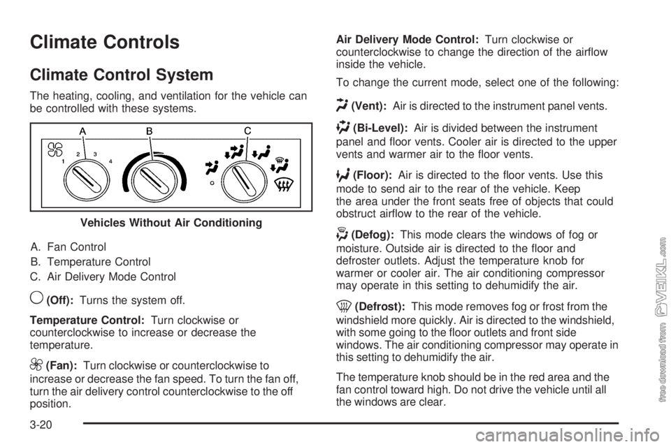
A. Fan Control
B. Temperature Control
C. Air Delivery Mode Control
9(Off):Turns the system off.
Temperature Control:Turn clockwise or
counterclockwise to increase or decrease the
temperature.
9(Fan):Turn clockwise or counterclockwise to
increase or decrease the fan speed. To turn the fan off,
turn the air delivery control counterclockwise to the off
position.Air Delivery Mode Control:Turn clockwise or
counterclockwise to change the direction of the airflow
inside the vehicle.
To change the current mode, select one of the following:
H(Vent):Air is directed to the instrument panel vents.
)(Bi-Level):Air is divided between the instrument
panel and floor vents. Cooler air is directed to the upper
vents and warmer air to the floor vents.
6(Floor):Air is directed to the floor vents. Use this
mode to send air to the rear of the vehicle. Keep
the area under the front seats free of objects that could
obstruct airflow to the rear of the vehicle.
-(Defog):This mode clears the windows of fog or
moisture. Outside air is directed to the floor and
defroster outlets. Adjust the temperature knob for
warmer or cooler air. The air conditioning compressor
may operate in this setting to dehumidify the air.
0(Defrost):This mode removes fog or frost from the
windshield more quickly. Air is directed to the windshield,
with some going to the floor outlets and front side
windows. The air conditioning compressor may operate in
this setting to dehumidify the air.
The temperature knob should be in the red area and the
fan control toward high. Do not drive the vehicle until all
the windows are clear. Vehicles Without Air Conditioning
3-20
Page 140 of 376

Rear Window Defogger
For vehicles with a rear window defogger, a warming
grid is used to remove fog or frost from the rear window.
The rear window defogger only works when the
ignition is in ON/RUN.
<(Rear):Press to turn the rear window defogger on
or off. An indicator light comes on to show that the
rear window defogger is on. Be sure to clear as much
snow from the rear window as possible.
The rear window defogger turns off several minutes
after the button is pressed. The defogger can also be
turned off by turning off the engine.
Notice:Do not use anything sharp on the inside of
the rear window. If you do, you could cut or damage
the warming grid, and the repairs would not be
covered by the vehicle warranty. Do not attach a
temporary vehicle license, tape, a decal or anything
similar to the defogger grid.
Outlet Adjustment
The vehicle has air outlets on the instrument panel that
adjust the direction and amount of airflow inside the
vehicle.
Move the lever on the outlet up or down to direct the
airflow. Increase or reduce the amount of airflow by
opening and closing the louvers. The outlets can be
moved side-to-side to direct the airflow.
Operation Tips
•
Keep the hood and front air inlets free of ice, snow,
or any other obstruction (such as leaves). The
heater and defroster will work far better, reducing
the chance of fogging the inside of the windows.
•Keep the air path under the front seats clear of
objects. This helps air to circulate throughout
the vehicle.
•Adding outside equipment to the front of the
vehicle, such as hood-air deflectors, may affect the
performance of the heating and air conditioning
system. Check with your dealer/retailer before
adding equipment to the outside of the vehicle.
3-22
Page 141 of 376

Rear Heating System
If the vehicle has a crew
cab and has a rear heater,
the thumbwheel for this
feature is located on
the headliner.
To increase and decrease the flow of heated air to the
rear floor vents, turn the thumbwheel to the desired
fan speed. To turn the fan off, turn the thumbwheel all
the way down.
Warning Lights, Gages, and
Indicators
Warning lights and gages can signal that something is
wrong before it becomes serious enough to cause
an expensive repair or replacement. Paying attention to
the warning lights and gages could prevent injury.
Warning lights come on when there may be or is a
problem with one of the vehicle’s functions. Some
warning lights come on briefly when the engine is started
to indicate they are working.
Gages can indicate when there may be or is a problem
with one of the vehicle’s functions. Often gages and
warning lights work together to indicate a problem with
the vehicle.
When one of the warning lights comes on and stays on
while driving, or when one of the gages shows there
may be a problem, check the section that explains what
to do. Follow this manual’s advice. Waiting to do
repairs can be costly and even dangerous.
3-23
Page 152 of 376
Trailer Antilock Brake System
Warning Light
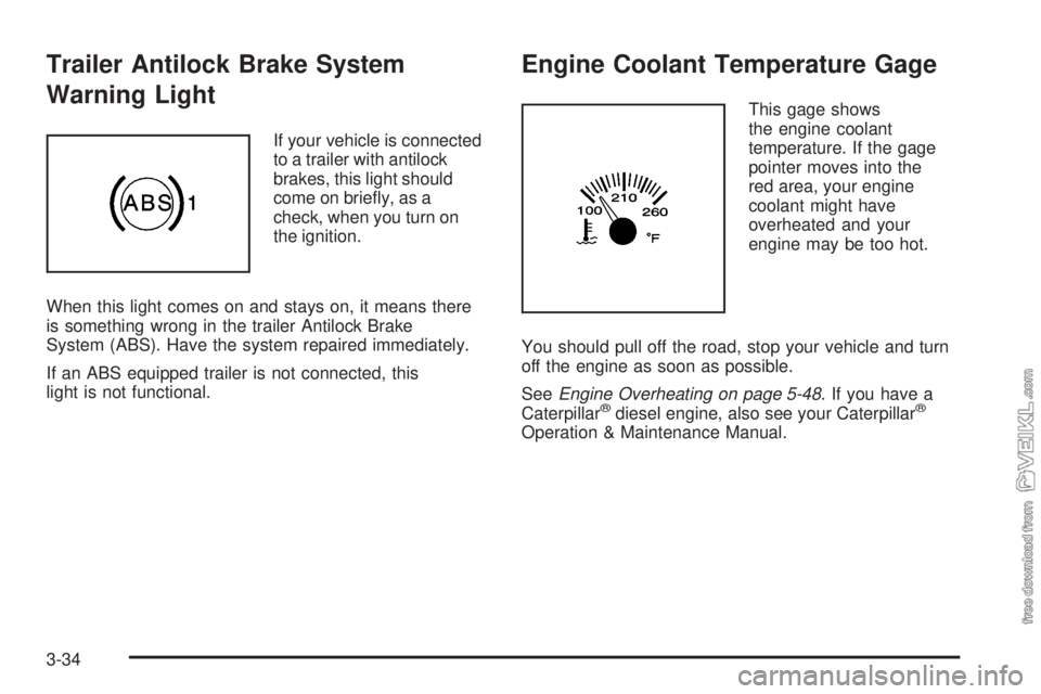
If your vehicle is connected
to a trailer with antilock
brakes, this light should
come on briefly, as a
check, when you turn on
the ignition.
When this light comes on and stays on, it means there
is something wrong in the trailer Antilock Brake
System (ABS). Have the system repaired immediately.
If an ABS equipped trailer is not connected, this
light is not functional.
Engine Coolant Temperature Gage
This gage shows
the engine coolant
temperature. If the gage
pointer moves into the
red area, your engine
coolant might have
overheated and your
engine may be too hot.
You should pull off the road, stop your vehicle and turn
off the engine as soon as possible.
SeeEngine Overheating on page 5-48. If you have a
Caterpillar
®diesel engine, also see your Caterpillar®
Operation & Maintenance Manual.
3-34
Page 203 of 376
Service............................................................5-3
Accessories and Modifications..........................5-3
California Proposition 65 Warning.....................5-4
California Perchlorate Materials Requirements.....5-4
Doing Your Own Service Work.........................5-5
Engine Fan Breakage.....................................5-6
Fuel................................................................5-6
Gasoline Octane............................................5-6
Gasoline Specifications....................................5-7
Additives.......................................................5-7
Diesel Engine Fuel.........................................5-8
What Fuel to Use...........................................5-8
Very Cold Weather Operation.........................5-11
Water in Fuel...............................................5-11
Running Out of Fuel.....................................5-17
Fuel Filter Replacement.................................5-18
Fuels in Foreign Countries.............................5-19
Filling the Tank............................................5-20
Filling a Portable Fuel Container.....................5-22
Checking Things Under the Hood....................5-22
Hood Latches...............................................5-23
Engine Oil (DURAMAX Diesel Engine).............5-24
Engine Oil (Caterpillar Diesel Engine)..............5-27
Engine Oil (Isuzu Diesel Engine).....................5-28
Engine Oil (Gasoline Engine)..........................5-32
Engine Oil Life System (Gasoline Engine)........5-35Engine Oil Life System (DURAMAX/Isuzu
Diesel Engines).........................................5-36
Engine Oil Life System (Caterpillar
Diesel Engine)..........................................5-38
Engine Air Cleaner/Filter................................5-38
Automatic Transmission Fluid.........................5-42
Manual Transmission Fluid.............................5-42
Cooling System............................................5-43
Engine Coolant (Caterpillar Diesel Engines)......5-47
Coolant Surge Tank Pressure Cap..................5-47
Engine Overheating.......................................5-48
Engine Fan Noise.........................................5-49
Power Steering Fluid.....................................5-49
Windshield Washer Fluid................................5-50
Brakes........................................................5-52
Battery........................................................5-61
Jump Starting...............................................5-62
Rear Axle.......................................................5-67
Rear Axle Shift Motor....................................5-68
Four-Wheel Drive............................................5-68
Front Axle......................................................5-69
Noise Control System.....................................5-70
Tampering with Noise Control System
Prohibited.................................................5-70
Bulb Replacement..........................................5-71
Section 5 Service and Appearance Care
5-1