CHEVROLET MALIBU 2004 5.G Owners Manual
Manufacturer: CHEVROLET, Model Year: 2004, Model line: MALIBU, Model: CHEVROLET MALIBU 2004 5.GPages: 426, PDF Size: 3.98 MB
Page 111 of 426
Gate Operator and Canadian
Programming
Canadian radio-frequency laws require transmitter
signals to “time out” or quit after several seconds of
transmission. This may not be long enough for
HomeLink
®to pick up the signal during programming.
Similarly, some U.S. gate operators are manufactured to
“time out” in the same manner.
If you live in Canada, or you are having difficulty
programming a gate operator by using the
“Programming HomeLink
®” procedures (regardless of
where you live), replace Step 3 under “Programming
HomeLink
®” with the following:
Continue to press and hold the HomeLink
®button while
you press and release every two seconds (cycle)
your hand-held transmitter until the frequency signal has
been successfully accepted by HomeLink
®. The
indicator light will �ash slowly at �rst and then rapidly.
Proceed with Step 4 under “Programming HomeLink
®”
to complete.
Using HomeLink®
Press and hold the appropriate HomeLink®button for at
least half of a second. The indicator light will come
on while the signal is being transmitted.
Erasing HomeLink®Buttons
To erase programming from the three buttons do the
following:
1. Press and hold down the two outside buttons until
the indicator light begins to �ash, after 20 seconds.
2. Release both buttons. Do not hold for longer than
30 seconds.
HomeLink
®is now in the train (learning) mode and can
be programmed at any time beginning with Step 2
under “Programming HomeLink
®.”
Individual buttons can not be erased, but they can be
reprogrammed. See “Reprogramming a Single
HomeLink
®Button” next.
2-43
Page 112 of 426
Reprogramming a Single HomeLink®
Button
To program a device to HomeLink®using a HomeLink®
button previously trained, follow these steps:
1. Press and hold the desired HomeLink
®button. Do
not release the button.
2. The indicator light will begin to �ash after
20 seconds. While still holding the HomeLink
®
button, proceed with Step 2 under “Programming
HomeLink®.”
Resetting Defaults
To reset HomeLink®to default settings do the following:
1. Hold down the two outside buttons for about
20 seconds until the indicator light begins to �ash.
2. Continue to hold both buttons until the HomeLink
®
indicator light turns off.
3. Release both buttons.
For questions or comments, contact HomeLink
®at
1-800-355-3515, or on the internet at
www.homelink.com.
Storage Areas
Glove Box
To open, pull the handle down and pull the glove box
door down until it stops and is fully open.
Cupholder(s)
The center console provides space for holding a cup or
soft drink container. One cupholder is located at the
rear of the shift lever and one is to the side of the shift
lever.
Pull down the door on the rear of the center console to
use the rear seat cupholders.
2-44
Page 113 of 426
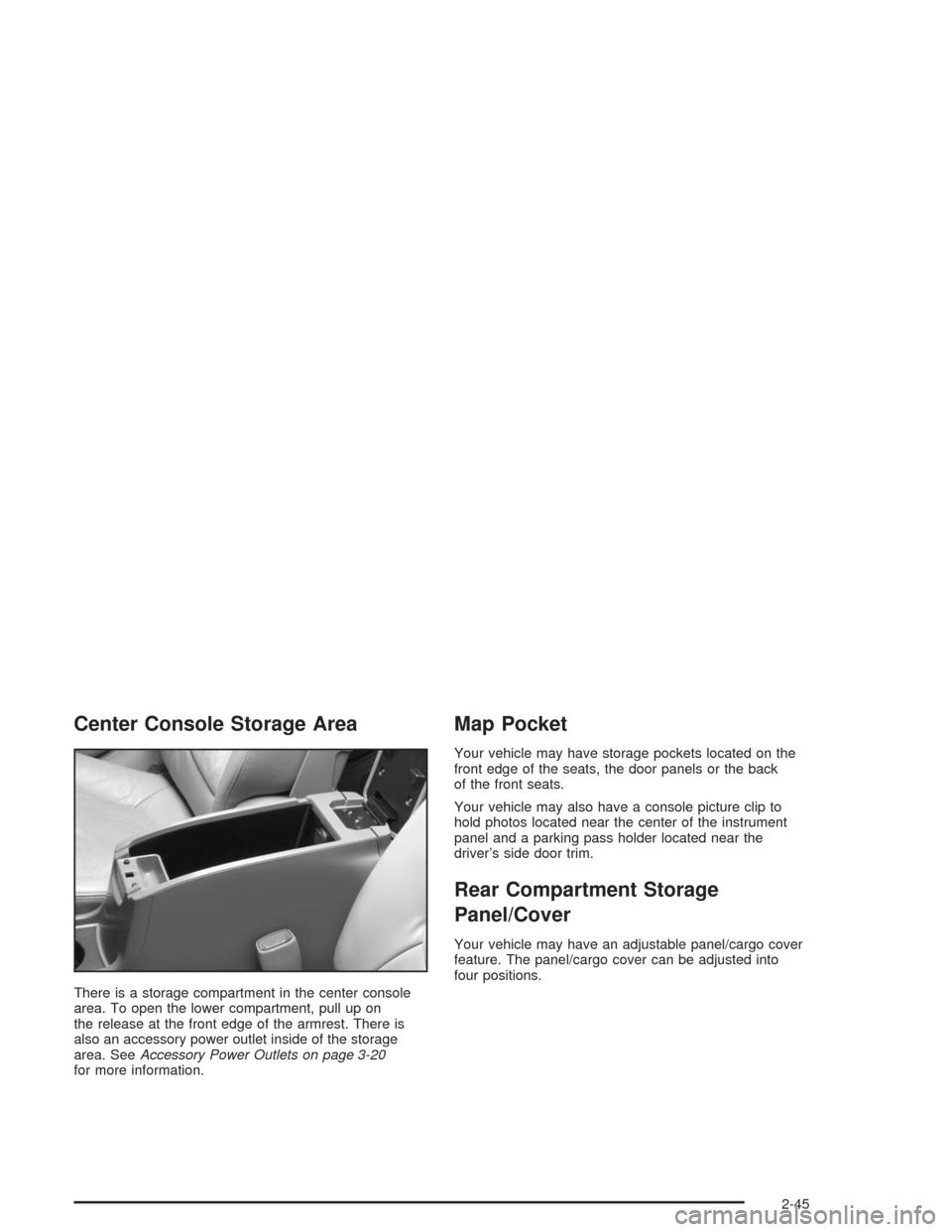
Center Console Storage Area
There is a storage compartment in the center console
area. To open the lower compartment, pull up on
the release at the front edge of the armrest. There is
also an accessory power outlet inside of the storage
area. SeeAccessory Power Outlets on page 3-20
for more information.
Map Pocket
Your vehicle may have storage pockets located on the
front edge of the seats, the door panels or the back
of the front seats.
Your vehicle may also have a console picture clip to
hold photos located near the center of the instrument
panel and a parking pass holder located near the
driver’s side door trim.
Rear Compartment Storage
Panel/Cover
Your vehicle may have an adjustable panel/cargo cover
feature. The panel/cargo cover can be adjusted into
four positions.
2-45
Page 114 of 426
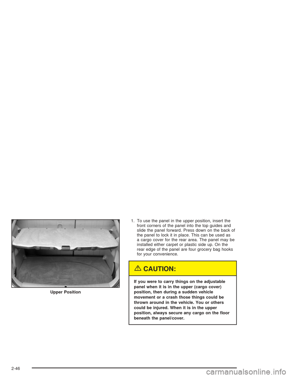
1. To use the panel in the upper position, insert the
front corners of the panel into the top guides and
slide the panel forward. Press down on the back of
the panel to lock it in place. This can be used as
a cargo cover for the rear area. The panel may be
installed either carpet or plastic side up. On the
rear edge of the panel are four grocery bag hooks
for your convenience.
{CAUTION:
If you were to carry things on the adjustable
panel when it is in the upper (cargo cover)
position, then during a sudden vehicle
movement or a crash those things could be
thrown around in the vehicle. You or others
could be injured. When it is in the upper
position, always secure any cargo on the �oor
beneath the panel/cover. Upper Position
2-46
Page 115 of 426
2. To use the panel in the center position, insert the
front corners of the panel into the middle guides
and slide the panel forward. Press down on
the back of the panel to lock it in place. The panel
can be used in this position when you have to
place a �at or spare tire on the �oor of the
rear cargo area.
3. The panel can be used in the lower position if you
need additional space above the panel. Place the
cargo on top of the panel in this position.
The panel/cargo cover can also be used as a table. See
“Table” following.
Table
The maximum load for the table is 100 lbs. (45 kg).
To set up the table, do the following:
1. With the adjustable panel in the upper position
extend the panel out, with the plastic side up.
2. Unsnap the leg from the plastic side of the table
and turn leg outward.
3. Set the table leg into the groove on the trim of the
rear edge of the vehicle.Make sure to place the table leg securely into the
groove. The shelf can only be extended in the upper
position.
Notice:Driving with the panel extended into the
table position could damage your vehicle. Always
have the panel in the stored position while you
are driving.
Notice:Placing hot items on the surface of the
table could damage it. Always be sure that the items
that are placed on the surface of the table are of
moderate temperature.
Convenience Net
The MAXX model has a rear compartment net to
prevent items from rolling under the rear seat.
2-47
Page 116 of 426
Sunroof
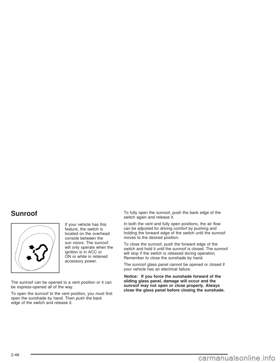
If your vehicle has this
feature, the switch is
located on the overhead
console between the
sun visors. The sunroof
will only operate when the
ignition is in ACC or
ON or while in retained
accessory power.
The sunroof can be opened to a vent position or it can
be express-opened all of the way.
To open the sunroof to the vent position, you must �rst
open the sunshade by hand. Then push the back
edge of the switch and release it.To fully open the sunroof, push the back edge of the
switch again and release it.
In both the vent and fully open positions, the air �ow
can be adjusted for driving comfort by pushing and
holding the forward edge of the switch until the sunroof
moves to the desired position.
To close the sunroof, push the forward edge of the
switch and hold it until the sunroof is closed. The sunroof
will stop if the switch is released during operation.
Remember to close the sunshade by hand.
The sunroof glass panel cannot be opened or closed if
your vehicle has an electrical failure.
Notice:If you force the sunshade forward of the
sliding glass panel, damage will occur and the
sunroof may not open or close properly. Always
close the glass panel before closing the sunshade.
2-48
Page 117 of 426
Instrument Panel Overview...............................3-4
Hazard Warning Flashers................................3-6
Other Warning Devices...................................3-7
Horn.............................................................3-7
Tilt Wheel.....................................................3-7
Turn Signal/Multifunction Lever.........................3-8
Exterior Lamps.............................................3-14
Interior Lamps..............................................3-19
Accessory Power Outlets...............................3-20
Climate Controls............................................3-21
Climate Control System.................................3-21
Automatic Climate Control System...................3-25
Outlet Adjustment.........................................3-30
Warning Lights, Gages, and Indicators............3-31
Instrument Panel Cluster................................3-32
Speedometer and Odometer...........................3-33
Tachometer.................................................3-33
Safety Belt Reminder Light.............................3-34
Air Bag Readiness Light................................3-34
Charging System Light..................................3-35
Brake System Warning Light..........................3-36
Anti-Lock Brake System
Warning Light...........................................3-37
Enhanced Traction System
Warning Light...........................................3-37
Enhanced Traction System Active Light............3-38Engine Coolant Temperature Warning Light......3-38
Engine Coolant Temperature Gage..................3-39
Malfunction Indicator Lamp.............................3-39
Oil Pressure Light.........................................3-42
Security Light...............................................3-43
Cruise Control Light......................................3-43
Service Vehicle Soon Light............................3-44
Fuel Gage...................................................3-44
Driver Information Center (DIC).......................3-45
DIC Operation and Displays...........................3-46
DIC Warnings and Messages.........................3-50
Audio System(s).............................................3-52
Setting the Time for Radios without Radio
Data Systems (RDS)..................................3-52
Setting the Time for Radios with Radio Data
Systems (RDS).........................................3-53
Radio with CD (Base Level)...........................3-53
Radio with CD (Up Level)..............................3-58
Radio with Cassette and CD..........................3-69
Radio with Six-Disc CD.................................3-82
Rear Seat Entertainment System....................3-96
Rear Seat Audio (RSA)
(Without Entertainment System).................3-111
Rear Seat Audio (RSA)
(With Entertainment System).....................3-113
Theft-Deterrent Feature................................3-115
Section 3 Instrument Panel
3-1
Page 118 of 426
Audio Steering Wheel Controls......................3-115
DVD Distortion............................................3-116
Radio Reception.........................................3-116
Care of Your Cassette Tape Player...............3-117
Care of Your CDs and DVDs........................3-118
Care of Your CD and DVD Player.................3-118Cleaning Your DVD Player...........................3-118
Cleaning the Video Screen...........................3-118
Fixed Mast Antenna (MAXX Only).................3-118
Backglass Antenna (Sedan Only)..................3-119
XM™ Satellite Radio Antenna System............3-119
Section 3 Instrument Panel
3-2
Page 119 of 426
✍NOTES
3-3
Page 120 of 426
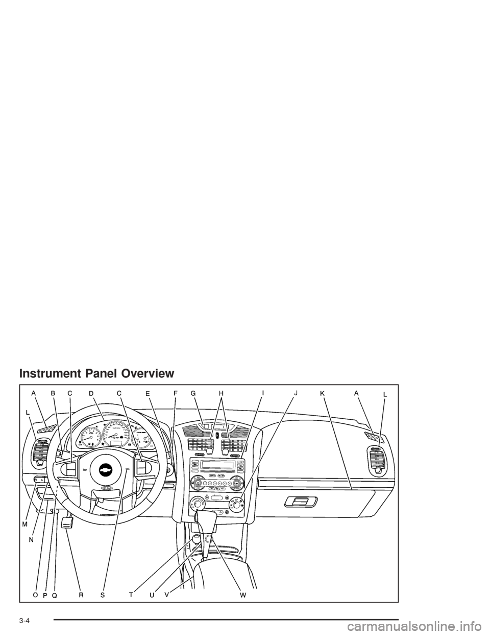
Instrument Panel Overview
3-4