light CHEVROLET MONTE CARLO 1973 2.G User Guide
[x] Cancel search | Manufacturer: CHEVROLET, Model Year: 1973, Model line: MONTE CARLO, Model: CHEVROLET MONTE CARLO 1973 2.GPages: 86, PDF Size: 33.46 MB
Page 28 of 86
Downloaded from www.Manualslib.com manuals search engine Instruments
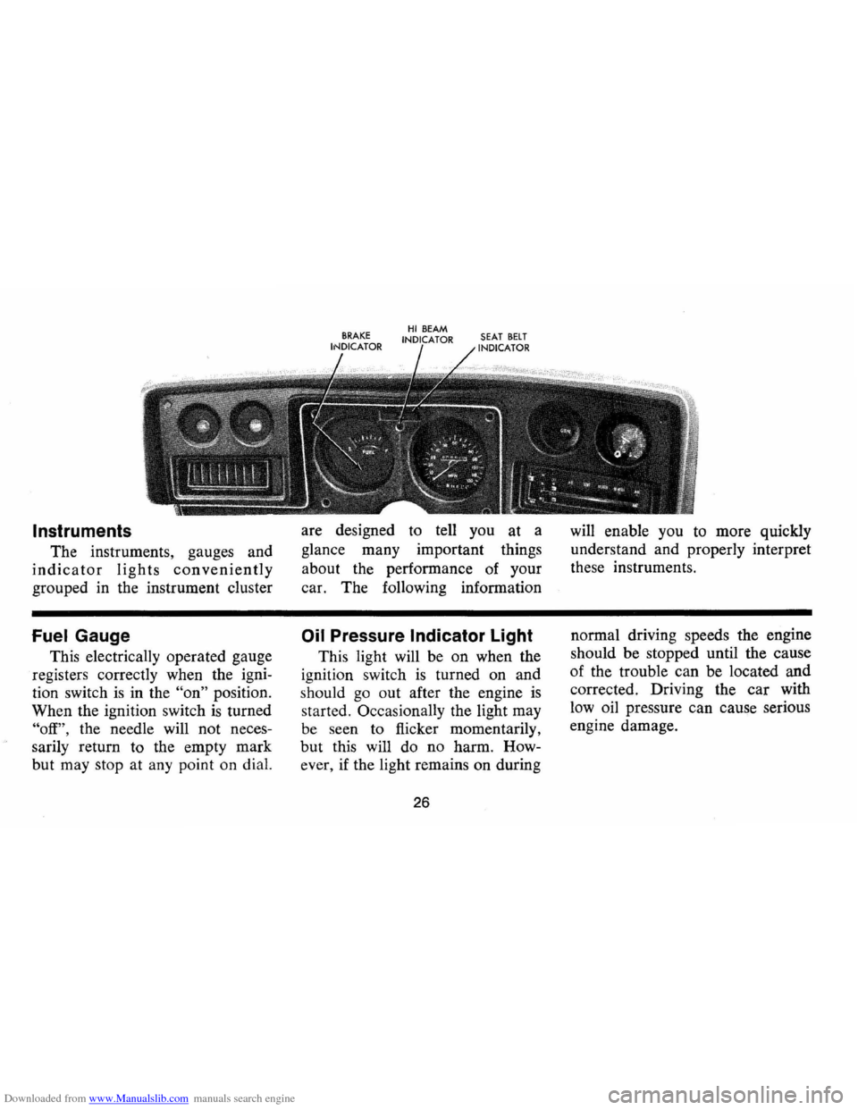
The instruments, gauges and
indicator lights conveniently
grouped in the instrument cluster
Fuel Gauge
This electrically operated gauge
registers correctly when the igni
tion switch
is in the "on" position.
When the ignition switch
is turned
"off", the needle will not neces
sarily return to the empty mark
but may stop at any point on dial. are
designed to tell you at a
glance many important things
about the performance of your
car. The foIlowing information
Oil Pressure Indicator Light
This light will be on when the
ignition switch
is turned on and
s hould
go out after the engine is
started. OccasionaIly the light may
be seen to flicker momentarily,
but this will do no harm. How
ever , if the light remains on during
26
will enable you to more quickly
understand and properly interpret
these instruments .
normal driving speeds the engine
should be stopped until the cause
of the trouble ca n be located and
corrected. Driving the
car with
low oil pressure can cause serious
engine damage.
Page 29 of 86
Downloaded from www.Manualslib.com manuals search engine Generator Indicator Light
This light provides a quick
check on the generating system
of your car. The red light will
go on when the ignition key
is
in the "on" position, but before
the engine
is started. After the
engine starts, the light should go
out and remain out.
If the light
remains on when engine
is run
ning , have your Authorized Chev
rolet Dealer locate and correct
the trouble
as soon as possible.
Engine Temperature
Indicator Light
This indicator light is provided
in the
instrument cluster to
quickly warn of an overheated
engine. With the ignition switch
in the
START position, the red
TEMP indicator will light to let
you know that it
is operating
properly. When the engine
is started, the red
light will go out immediately.
It will light up at no other time
unless for some reason the engine
reaches a dangerously high oper
ating temperature.
If the red light
should come on, the engine must
be stopped until the cause of the
overheating
is corrected. Glance
at instrument cluster frequently
as
you drive to see if this light is on.
Brake System Warning Light
The service brake system is
designed so that half of the brake
system will provide some braking
action in the event of a hydraulic
leak in the other half of the
sys
tem. If the warning light located
below the fuel gauge glows con
tinuously when the ignition
is on
and after the brakes have been
firmly applied, it may indicate that
there
is a malfunction in one half
of the brake hydraulic system.
27
• As a check on bulb condition
the light should glow with the
parking brake applied and the
ignition on. (Light
is also a
reminder to release parking
brake) .
• Have system repaired if light
does not come on during check.
• This warning light is not a sub
stitute for the visual check of
brake fluid level required
as
part of normal maintenance.
If the light glows red:
• The parking brake control is not
fully released or,
• The service brake system is
partially inoperative
What to do:
1. Check that the parking brake
is released. If it is ...
2. Pull off the road and stop,
carefully- remembering that:
Page 30 of 86
Downloaded from www.Manualslib.com manuals search engine • Stopping distances may be
greater.
• Greater pedal effort may be
required .
• Pedal travel may be greater.
3.
Tryout braking operation by
starting and stopping on road
shoulder -then:
• If you judge such operation
to be safe , proceed cautious
ly
at a s afe speed to nearest
dealer for repair.
• Or have car towed to dealer
for repair.
Continued operation of the car
in this condition
is dangerous.
Headlight Beam Indicator
Light
The headlights of your car have
high and low beams to provide
ybu
with proper night-time visibility
for most driving conditons . The
"low" beams are used during most
city driving. The "high" beams are especially
useful when driving
on
dark roads since they provide ex
cellent long range illumination.
The headlight beam indicator will
be on whenever the high beams
or
"brights" are in use. The Headlight
Beam Switch controls the headlight
beams (see
Page 24).
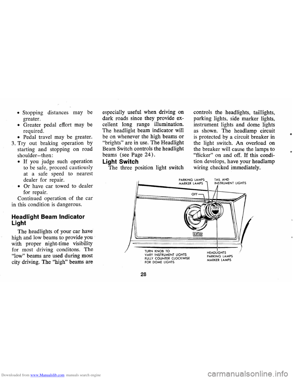
Light Switch
The three position light switch controls
the headlights, taillights,
parking lights, side marker lights,
instrument lights and dome lights
as shown. The headlamp circuit
is protected by a circuit breaker in
the light switch. An overload on
the breaker will cause the lamps to
"flicker" on and off. If this condi
tion develops, have your headlamp
wiring checked immediately.
PARKING LAMPS MARKER LAMPS TAIL AND INSTRUMENT LIGHTS
--,---.---~------ -- --------
TURN KNOB TO VARY INSTRUMENT LIGHTS fULLY COUNTER CLOCKWISE fOR DOME LIGHTS
28
HEADLIGHTS PARKING LAMPS MARKER LAMPS
•
Page 31 of 86
Downloaded from www.Manualslib.com manuals search engine _ '\' ' 2
1
5 , / '/ ,
[ e /~
O'v RPM !lOa -"-50
Optional Instrument and
Gauges
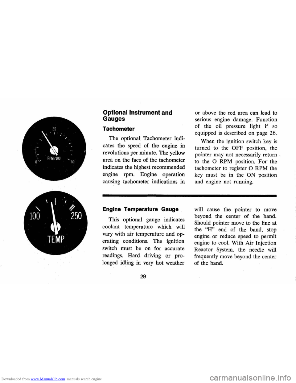
Tachometer
The optional Tachometer indi
cates the speed of the engine in
revolutions per minute. The yellow
area on the face of the tachometer
indicates the highest recommended
engine rpm. Engine operation
causing tachometer indications in
Engine Temperature Gauge
This optional gauge indicates
coolant temperature which will
vary with air temperature and op
erating conditions. The ignition
switch must be on for accurate
readings. Hard driving
or pro
longed idling in very hot weather
29
or above the red area can lead to
serious engine damage. Function
of the oil pressure light if
so
equipped is described on page 26.
When the ignition switch key
is
turned to the OFF position, the
pointer may not necessarily return
'
to the 0 RPM position. For the
tachometer
to register 0 RPM the
key must be in the
ON position
and engine not running.
will cause the pointer to move
beyond the center of the band.
Should pointer move to the line at
the
"H" end of the band, stop
engine
or reduce speed to permit
engine to cool. With Air Injection
Reactor System, the needle will
frequently move beyond the center
of the band.
Page 33 of 86
Downloaded from www.Manualslib.com manuals search engine Clock
Reset the clock , by pulling out
the knob and turning the hands
clockwise
if slow, counterclockwise
if fast. This will, if the clock error
is five minutes or more, automati
cally compensate for time gain or
lag . Several resettings, several days
apart, may be needed to propertly
adjust the clock mechanism. Have
your clock cleaned and oiled by a
competent clock serviceman at
least every two years.
Cigarette Lighter
The cigarette lighter is located
on the instrument panel face.
To
operate, push it in. When it be
comes heated, it automatically pops
out ready for use.
Windshield Wiper and
Washer
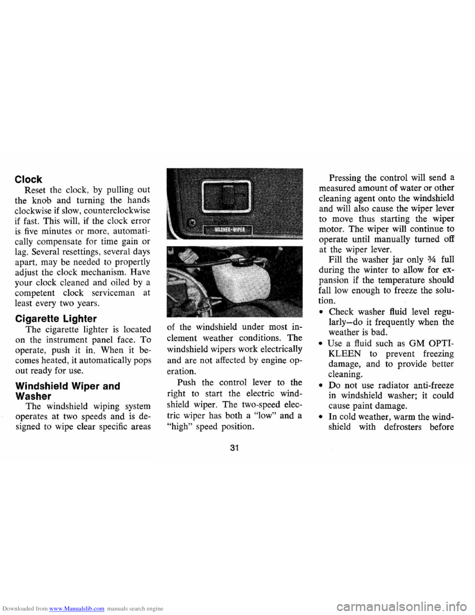
The windshield wiping system
operates at two speeds and
is de
signed to wipe clear specific areas of
the windshield under most in
clement weather conditions . The
windshield wipers work electrically
and are not affected by engine op
eration. Push the control lever to the
right to start the electric wind
shield wiper. The two-speed elec
tric wiper has both a "low" and a
"high" speed position.
31
Pressing the control will send a
measured amount of water or other
cleaning agent onto the windshield
and will also cause the wiper lever
to move thus starting the wiper
motor. The wiper will continue to
operate until manually turned off
at the wiper lever.
Fill the washer jar only
% full
during the winter to allow for ex
pansion if the temperature should
fall low enough to freeze the solu
tion .
• Check washer fluid level regu
larly-do it frequently when the
weather is bad .
• Use a fluid such as GM OPTI
KLEEN to prevent freezing
damage, and to provide better
cleaning.
• Do not use radiator anti-freeze
in windshield washer; it could
cause paint damage.
• In cold weather, warm the wind
shield with defrosters before
Page 40 of 86
Downloaded from www.Manualslib.com manuals search engine Chevrolet HAil Transistor" Radios
To operate the radios, the igni
tion switch must be in "ON" or
"ACC" position.
r------_·_-
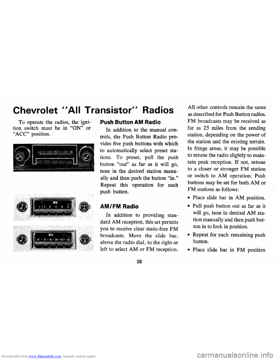
Push Butt.on AM Radio
In addition to the manual con
trols , the Push Button Radio pro
vides five push buttons with which
to automatically select preset
sta
tions. To preset , pull the push
button
"out" as far as it will go,
tune in the desired station
manu
ally and then push the button "in."
Repeat this operation for each
push button.
!, 11111, II >, -ij 10 1/ Il '" I 1 AM/FM Radio
I.:"" :~ ;:--'.-'.-:'---~ -
.--.. -WI .. il~ • q2 -f~6 -lor ~ lOl -loa ~~,.."... -~-~.-.. ---_ ll'1 S. ...
In addition to providing stan
dard AM reception, this set permits
you to receive clear static-free
FM
broadcasts. Move the slide bar ,
above the radio dial, to the right or
left to select AM or FM reception.
38
All other controls remain the same
as described for Push Button radios.
FM broadcasts may be received as
far as 25 miles from the sending
station , depending on the power of
the station and the existing terrain.
In fringe areas, it may
be possible
to retune the radio slightly to
main
tain peak reception . If not, retune
to a closer or stronger
FM station
or switch to AM operation. Push
buttons may be set for both
AM or
FM stations as follows:
• Place slide bar in AM position.
• Pull push button out as far as it
will go, tune in desired AM
sta
tion manually and then push but
ton in to lock in position.
• Repeat for each remaining push
button.
• Place slide bar in FM position
Page 41 of 86
Downloaded from www.Manualslib.com manuals search engine and repeat procedures outlined
for AM band setting.
NOTE: Bands cannot be changed
if push button
is unlocked.
Antenna
The radio antenna is incorpo
rated in the windshield glass.
If
necessary, adjustments for maxi
mum antenna effectiveness can be
made
by your authorized Chevro
let dealer.
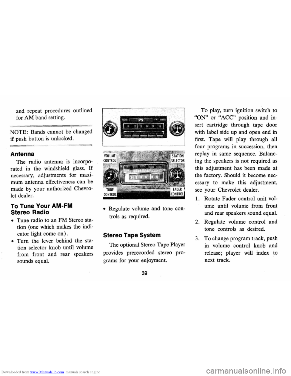
To Tune Your AM-FM
Stereo Radio
• Tune radio to an FM Stereo sta
tion (one which makes the indi
cator light come
on).
• Turn the lever behind the sta
tion selector knob until volume
from front and rear speakers
sounds equal.
• Regulate volume and tone con
trols
as required.
Stereo Tape System
The optional Stereo Tape Player
provides prerecorded stereo pro
grams for your enjoyment.
39
To play, turn ignition switch to
"ON" or "ACC" position and in
sert cartridge through tape door
with label side up and open end
in
first. Tape will play through all
four programs in succession , then
replay in same sequence. Balanc
ing the speakers
is not required as
this adjustment has been made at
the factory. Should it become nec
essary to make this adjustment,
see your Chevrolet dealer.
1. Rotate Fader control unit vol
ume until volume from front
and rear speakers sound equal.
2. Regulate volume control and
tone controls
as desired.
3. To change program track, push
in volume control knob and
release; player will index to
next track.
Page 43 of 86
Downloaded from www.Manualslib.com manuals search engine I n Case of Emergency
Four Way Hazard
Warning
Flasher
• Use the warning flasher to warn
other drivers any time your
ve
hicle becomes a traffic hazard,
day
or night.
• Avoid stopping on the roadway
if possible.
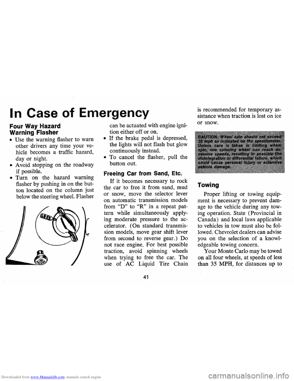
• Turn on the hazard warning
flasher by pushing in on the but
ton located on the column
just
below the steering wheel. Flasher
---~
can be actuated with engine igni
tion either off or on.
• If the brake pedal is depressed,
the lights will not flash but glow
continuously instead.
• To cancel the flasher, pull the
button out.
Freeing Car from Sand, Etc.
If it becomes necessary to rock
the car to free it from sand, mud
or snow, move the selector lever
on automatic transmission models
from
"D" to "R" in a repeat pat
tern while simultaneously apply
ing moderate pressure
to the ac
celerator.
(On standard transmis
sion models, move gear shift lever
from second to reverse gear.) Do
not race engine. For best possible
traction, avoid spinning wheels
when trying to free the car. The
use of AC Liquid Tire Chain
41
is recommended for. temporary as
sistance when traction is lost on ice
or snow.
Towing
Proper lifting or towing equip
ment
is necessary to prevent dam
age to the vehicle during any tow
ing operation.
State (Provincial in
Canada) and local laws applicable
to vehicles in tow must also be fol
lowed. Chevrolet dealers can advise
you on the selection of a knowl
edgeable towing concern.
Your Monte Carlo may be towed
on all four wheels, at speeds of less
than 35 MPH, for distances up to
Page 45 of 86
Downloaded from www.Manualslib.com manuals search engine or property damage. All General
Motors cars have negative-ground
electrical systems and can be used
to jump start one another.
If you
cannot determine how the other
vehicle
is grounded (by checking
specifications in the owner's man
ual, etc.) we recommend that you
attempt no jump starting with that
vehicle.
Jump Starting with
Auxiliary (Booster) Battery
Both booster and discharged
battery should be treated carefully
when using jumper cables. Follow
exactly the procedure outlined be
low, being careful not to cause
sparks:
1.
Set parking brake and place
automatic transmission in
"PARK" (neutral for manual
transmission).
Turn off lights,
heater and other electrical loads. 2.
Remove vent caps from both
the booster and the discharged
batteries. Lay a cloth over the
open vent wells of each battery.
These two actions help reduce
the explosion hazard always
present in either battery when
connecting
"live" booster bat
teries to
"dead" batteries.
3. Attach one end of one jumper
cable to the positive terminal of
the booster battery (identified
by a red color,
"+" or "P" on
the battery case, post or clamp)
and the other end of same cable
to positive terminal of discharged
battery. Do
NOT permit cars to
touch each other,
as this could
'establish a ground connection
and counteract the benefits of
this procedure.
4. Attach one end of the remaining
negative cable to the negative
terminal (black color,
"-" or
"N") of the booster battery, and
43
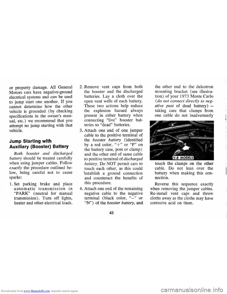
the other end to the' de1cotron
mounting bracket (see illustra
tion) of your 1973 Monte Carlo
(do not connect directly to neg
ative post of dead battery) -
taking care that clamps from
one cable do not inadvertently
touch the clamps on the other
cable. Do not lean over the
battery when making this con
nection.
Reverse this sequence exactly
when removing the jumper cables.
Re-install vent caps and throw
cloths away
as the cloths may have
corrosive acid on them.
Page 49 of 86
Downloaded from www.Manualslib.com manuals search engine Cleaning Fabrics with
Cleaning
Fluid
This type of cleaner should be
used for cleaning stains containing
grease, oil or fats. Excess stain
should be gently scraped off with
a clean dull knife or scraper.
Use
very little cleaner, light pressure,
and clean cloths (preferably cheese
cloth). Cleaning action with
cloth should be from outside of
stain towards center and constantly
changing to a clean section of
cloth. When stain
is cleaned from
fabric, immediately wipe
area
briskly with a clean absorbent
towel or cheese cloth to help dry
area and prevent a cleaning ring.
If ring forms, immediately clean
entire area or panel section of the
trim assembly.
NOTE: Sometimes a difficult spot
may require a second application
of cleaning fluid followed immedi
ately by a soft brush to completely
remove the spot.
Cleaning Fabrics with
Detergent Foam Cleaners
This type of cleaner is excellent
for cleaning general soilage from
fabrics and for cleaning a panel
section where a minor cleaning
ring may be left from spot clean
ing. Vacuum area to remove ex
cess loose dirt. Always clean at
least a full trim panel or section
of trim. Mask adjacent trim along
stitch or weld lines. Mix detergent
type foam cleaners in strict ac
cordance with directions on label
of container.
Use foam only on a
clean sponge or soft bristle brush
-Do not wet fabric excessively or
47
rub harshly with brush. Wipe clean
with a slightly damp absorbent
towel or cloth. Immediately after
cleaning fabric, dry fabric with a
dry towel or hair dryer. Rewipe
fabric with dry absorbent towel or
cloth to restore luster of the trim
and to eliminate any dried residue.
Seat Belt Care
• Clean only with mild soap solu
tion and lukewarm water.
• Do not bleach or dye belts since
this may severely weaken belts.
Removal of Specific Stains
Candy-Chocolate, use cloth soak
ed in lukewarm water; other than
chocolate, use very hot water. Dry.
If necessary, clean lightly with
fabric cleaning fluid.
Chewing Gum-Harden gum with
ice cube and scrape off with dull
knife. Moisten with fabric cleaning
fluid and scrape again,