light CHEVROLET MONTE CARLO 1973 2.G Owners Manual
[x] Cancel search | Manufacturer: CHEVROLET, Model Year: 1973, Model line: MONTE CARLO, Model: CHEVROLET MONTE CARLO 1973 2.GPages: 86, PDF Size: 33.46 MB
Page 5 of 86
Downloaded from www.Manualslib.com manuals search engine BEFORE DRIVING YOUR MONTE CARLO
DRIVER CHECKLIST
Before Entering Car
1. See that windows , mirrors and
lights are clean.
2 . Visually note inflation condition
of tires.
3. Check that area to rear is clear
if about to back up.
Before Driving Off
1. Lock all doors.
2. Position seat and adjust head
restraints.
3. Adjust inside and outside mir
rors.
4 . Fasten seat belts.
5. Check that warning bulbs light
when key
is turned to start posi
tion.
6 . Release parking brake (and see
that brake warning light turns
off). 7
. Be sure you understand your
car and how to operate it safely.
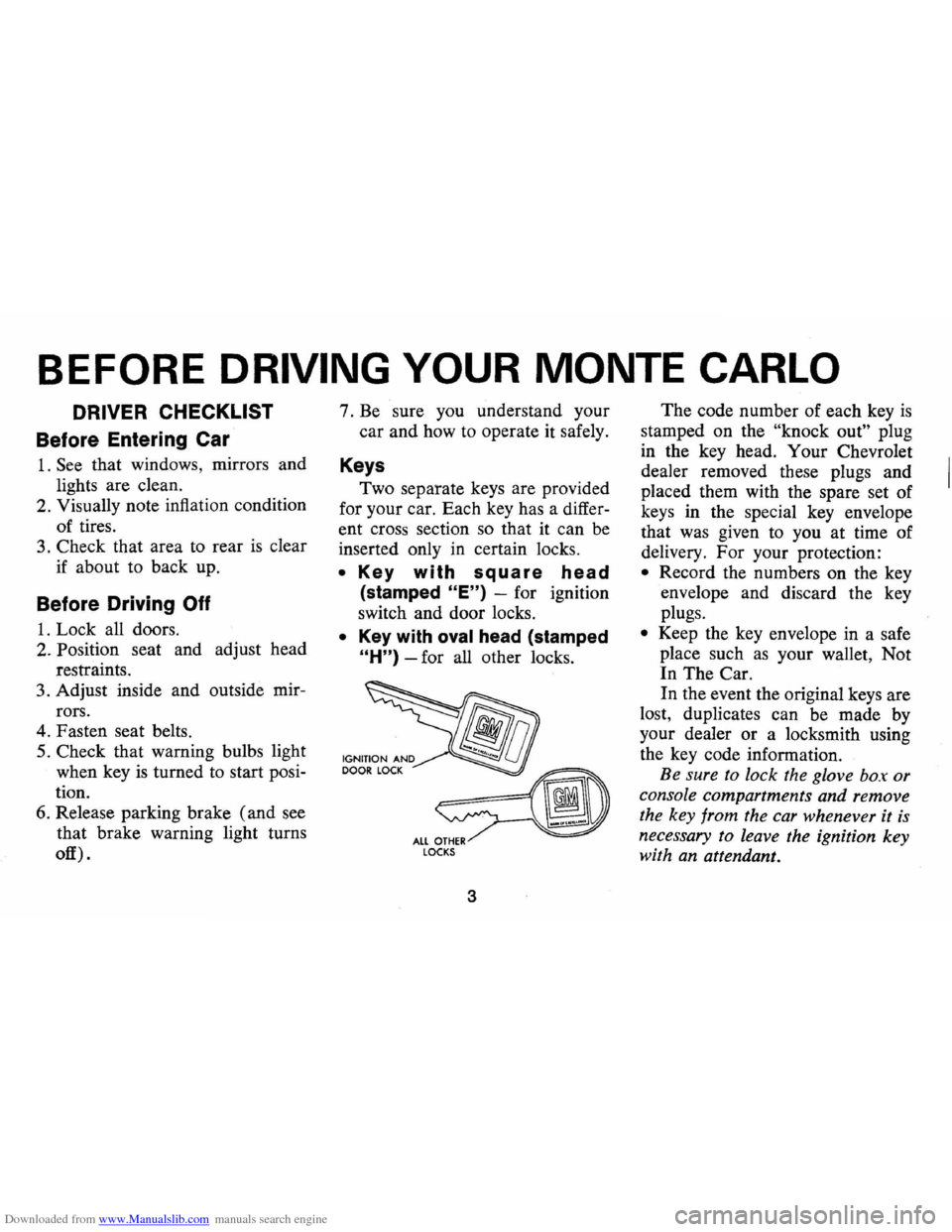
Keys
Two separate keys are provided
for your car. Each key has a differ
ent cross section so that it can be
inserted only
in certain locks.
• Key with square head
(stamped "E") -for ignition
switch and door locks.
• Key with oval head (stamped
"H") -for all other locks.
fib
~ ALL OTHER LOCKS
3
The code number of each key is
stamped on the "knock out" plug
in the key head. Your Chevrolet
dealer removed these plugs and
placed them with the spare set of
keys in the special key envelope
that was given to you at time of
delivery. For your protection:
• Record the numbers on the key
envelope and discard the key
plugs.
• Keep the key envelope in a safe
place such
as your wallet, Not
In The Car.
In the event the original keys are
lost, duplicates can be made by
your dealer or a locksmith using
the key code information.
Be sure to lock the glove box or
console compartments and remove
the key from the car whenever it
is
necessary to leave the ignition key
with an attendant.
Page 6 of 86
Downloaded from www.Manualslib.com manuals search engine Door Locks
Front side doors can be locked
from the inside by depressing the
passenger guard door lock buttons
located on the upper door panel.
All doors can be locked from the
outside by first depressing the door
lock button and closing the door.
The front doors can also be
locked by using the key.
All models have
as a standard
safety feature overriding door locks.
When the doors are locked, the
door latch mechanism
is inopera
tive, preventing inadvertent open
ing of the door by movement of the
inside handle.
REMINDER: Avoid hanging ob
jects on the right hand coat hook
in such a way that you block the
driver's vision to the right rear
quarter.
REMINDER: Always lock the
doors when driving, for greater se
curity in the event of an accident
and for security against entry by
unwelcome persons while momen
tarily stopped.
Seats
Folding seatbacks are equipped
with self-latching mechanisms and
release controls designed for the
convenience of entering and exit
ing passengers.
Manually Operated Front Seats
-The front seat can be moved
forward or rearward by moving the
control lever on the driver's side
of the seat forward and exerting
slight body pressure in the direc
tion desired. Release the lever
so
the seat will lock in the desired
position.
Back Locks-For your safety each
folding front seatback has a lock
4
which must be released before the
seatback can be folded forward.
The release lever
is located at the
lower side of each backrest nearest
the door. Move the lever upward,
then pull the seatback forward.
Keep seat belts and
bu.c~les
clear of mechanism when tlltmg
folding seats forward or backwards,
to prevent damage to these belt
restraints.
Bucket Seats
The front seats may be adjusted
to suit an individual's preference.
Simply release the seat lock mech
anism located at the front of the
seat.
Once released, exert slight
body pressure in the direction de
sired. Release the lever so the seat
will lock in the desired position.
Swivel Bucket Seats
The swivel bucket seat can be
turned towards the door opening
Page 8 of 86
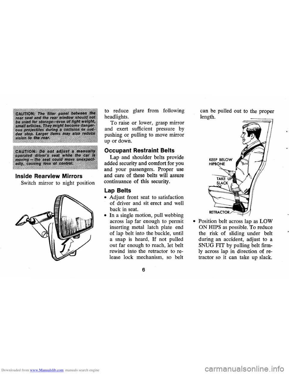
Downloaded from www.Manualslib.com manuals search engine Inside Rearview Mirrors
Switch mirror to night position to
reduce glare from following
headlights.
To raise or lower, grasp mirror
and exert sufficient pressure by
pushing
or pulling to move mirror
up
or down.
Occupant Restraint Belts
Lap and shoulder belts provide
added security and comfort for you
and your passengers.
Proper use
and care of these belts
will assure
continuance of this security.
lap Belts
• Adjust front seat to satisfaction
of driver and sit erect and well
back in seat.
• In a single motion, pull webbing
across lap far enough to permit
inserting metal latch plate end
of lap belt into the buckle, until
a snap
is heard. If not pulled
out far enough to reach, let belt
rewind into the retractor to re
lease lock mechanism ,
so belt
6
can be pulled out to the proper
length.
• Position belt across lap as LOW
ON HIPS
as possible. To reduce
the risk of sliding under belt
during an accident, adjust to a
SNUG FIT by pulling belt firm
ly across lap in direction of re
tractor
so it can take up slack.
Page 10 of 86
Downloaded from www.Manualslib.com manuals search engine Seat Belt Buzzer/Light
Reminder
• The front outboard lap belts
(those next to side windows)
are linked to a buzzer and light
which remind occupants to
fas
ten seat belts.
• On cars with automatic trans
missions, or manual transmis
sions with steering column
mounted shift levers , the buzzer
and light are designed to come
on when the ignition switch
is
on, the transmission selector is
in a forward drive position, and
the driver's or right front pas
senger's lap belt
is not fastened.
• On manual transmission cars
with floor mounted shift controls
the reminders are designed to
come on when the ignition switch
is on, the driver's or right front
passenger's lap belt
is not fas
tened and the transmission
is in
any gear position, except that
NOTE: The right front seat con
tains a weight detector which
is de
signed to activate the buzzer and
light whenever a nominal weight
is placed on the seat. The weight
detector cannot distinguish be
tween a passenger and any item
of luggage or cargo, therefore such
items should be placed elsewhere
in the car, preferably
in the trunk.
they do not come on when
t~e
parking brake is engaged.
If seat belt system or reminder
system does not work
as described,
see your dealer for information
and assistance.
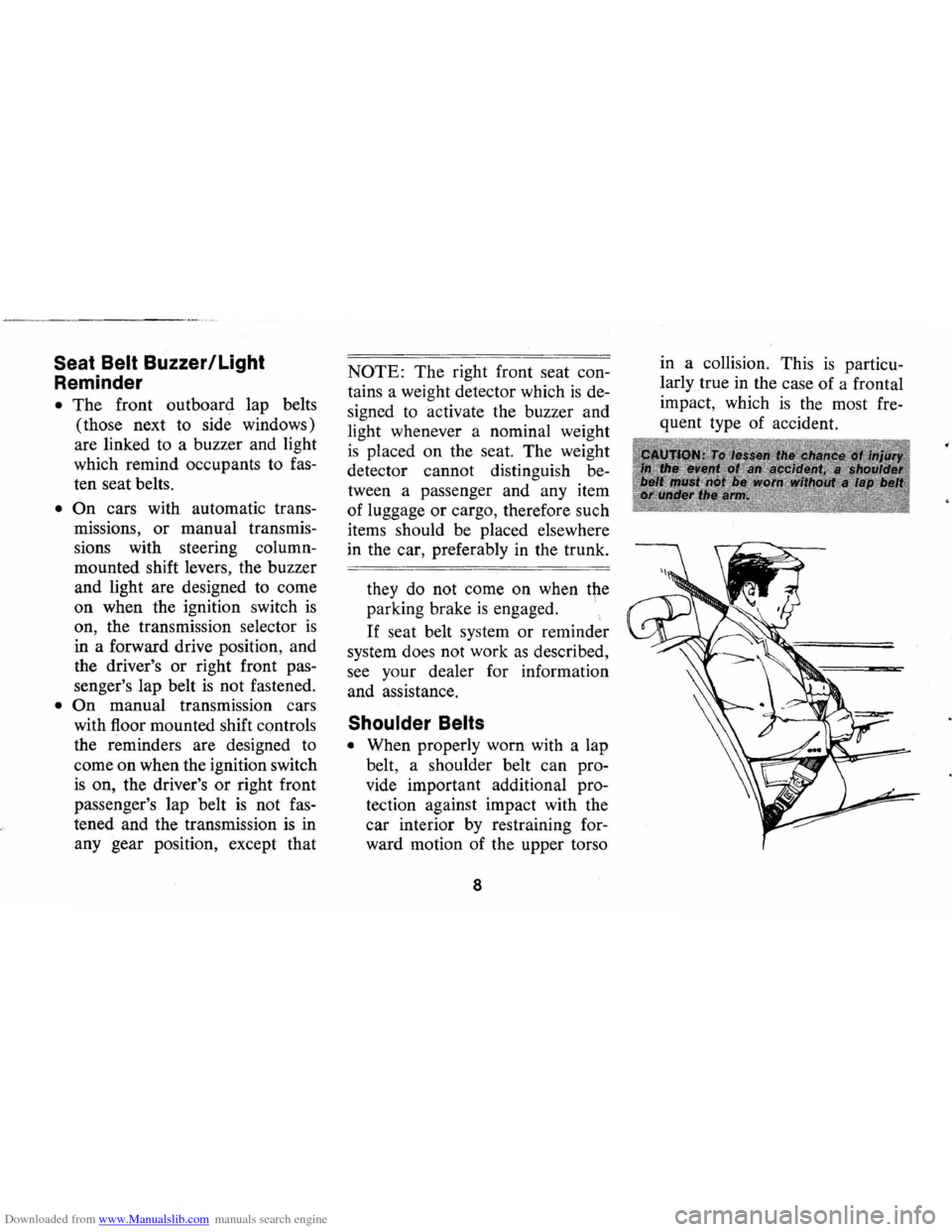
Shoulder Belts
• When properly worn with a lap
belt, a shoulder belt can pro
vide . important additional pro
tection against impact with the
car interior
by restraining for
ward motion of the upper torso
8
in a collision. This is particu
larly true in the case of a frontal
impact, which
is the most fre
quent type of accident.
Page 18 of 86
Downloaded from www.Manualslib.com manuals search engine 2. Place transmission selector
in uP" or uN" (UP" preferred).
A starter safety switch prevents
starter operation while the trans
mission selector
is in any drive
position.
(If it is necessary to
re-start the engine with the car
moving, place the selector lever
in
"N".)
3. Depress accelerator pedal and
activate starter
as outlined be
low for different conditions.
• Cold Engine -Fully de
press
accelerator pedal and
slowly release.
With foot off
the pedal, crank the engine
by turning the ignition key
to the Start position-release
when engine starts.
If engine starts, but fails to
run, repeat this procedure.
When engine is running
smoothly (approximately 30
seconds), the idle speed may
be reduced by slightly de- pressing
the accelerator pedal
and then slowly releasing.
• Warm Engine -Depress ac
celerator
pedal about halfway
and hold while cranking the
engine.
• Extremely Cold Weather
(Below 0° F.) Or After Car
Has Been Standing
Idle
Several
Oays-
Fully depress and release
accelerator pedal two or three
times before cranking the
engine.
With foot off the ac
celerator pedal,
crank the
engine by turning the key to
the Start position and release
when engine starts.
Manual Transmission Models
1. Apply parking brake and shift
16
transmission to neutral.
2.
Hold clutch pedal to floor
throughout the starting proce
dure.
A starter interlock pre
vents starter operation when
clutch
is not fully depressed.
(Select the proper gear position
before releasing the clutch pedal.)
3. Operate accelerator pedal and
starter
as outlined in step 3
(under Automatic Transmission
Models).
Engine Flooded
Depress accelerator pedal aJ;ld
hold to floor while starting until
engine
is cleared of excess fuel
and
is running smoothly. Never
"pump" the accelerator pedal.
Warm-Up
Always let the engine idle for
20 to 30 seconds after starting
and drive at moderate speeds for
several miles, especially during
cold weather.
Page 22 of 86
Downloaded from www.Manualslib.com manuals search engine Turn Signal and Lane
. Change Features
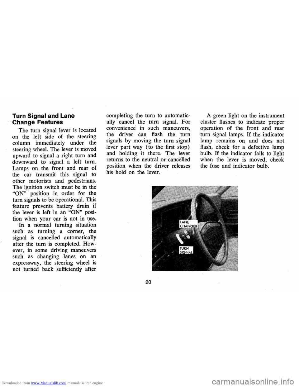
The tum signal lever is located
on the left side of the steering
column immediately under the
steering wheel. The lever
is moved
upward to signal a right
tum and
downward to signal a left tum.
Lamps on the front and rear of
the car transmit this signal to
other motorists and pedestrians.
The ignition switch must be in the
"ON" position in order for the
turn signals to be operational. This
feature prevents battery drain if
the lever
is left in an "ON" posi
tion when your car
is not in use.
In a normal turning situation
such
as turning a comer, the
signal
is cancelled automatically
after the tum
is completed. How
ever, in some driving maneuvers
such
as changing lanes on an
expressway, the steering wheel
is
not turned back sufficiently after completing
the
tum to automatic
ally cancel the turn signal.
For
convenience in such maneuvers,
the driver can flash the
tum
signals by moving the tum signal
lever part way (to the first stop)
and holding it there. The lever
returns to the neutral
or cancelled
position when the driver releases
his hold on the lever.
20
A green light on the instrument
cluster flashes to indicate proper
operation of the front and rear
tum signal lamps. If the indicator
lamp remains on and does not
flash, check for a defective lamp
bulb.
If the indicator fails to light
when the lever
is moved, check
the fuse and indicator bulb.
Page 24 of 86
Downloaded from www.Manualslib.com manuals search engine your foot from the accelerator.
If control button is not fully de
pressed, when changing speed
setting,
. the car will resume your
previously selected speed.
To disengage system, lightly de
press brake pedal or fully de
press the control button.
Horn
The hom on your Monte Carlo
is actuated · by firmly pressing on
the pad in the center of the steering
wheel. As a good motorist, use of the
horn should be kept at a minimum.
However, acquaint yourself
as soon
as possible with this function of
your car, should it ever become
necessary to give a warning to a
pedestrian
or another motorist.
Holding Car on an Upgrade
When stopped on an upgrade,
maintain your position by apply
ing the brakes. Never hold the
car in place by accelerating en-gine
with transmission in gear.
This could cause damage by over
heating the transmission (auto
matic)
or clutch (manual).
Parking Your Car
Always engage the parking
brake and place the automatic
transmission selector lever in
"Park" position when leaving your
car unattended. Also with auto
matic transmissions, never park
for prolonged periods with engine
idling and transmission in gear,
especially if your car
is equipped
with air conditioning. This prac
tice
is detrimental to the trans
mission, due to overheating.
NOTE: For operation of hazard flasher, see page 41, in Section "In Case of Emergency."
22
Page 25 of 86
Downloaded from www.Manualslib.com manuals search engine FLOOR CONTROLS
Braking System
The service brake system is de
signed for braking performance
under a wide range of driving con
ditions even when the vehicle
is
loaded to its full rated vehicle load.
Power Brakes
• On cars with power brakes if
power assist to the brakes
is
interrupted due to a stalled en
gine
or some malfunction, two
or more brake applications can
be made using reverse power.
• If the brake pedal is held down ,
the system
is designed to bring
the car to a full stop on reserve
power. However, the reserve
power
is partially depleted each
time the brake pedal
is applied
and released.
• When reserve power is ex- hausted,
the vehicle can still be
stopped by applying greater
force to the pedal.
Parking Brake
• To set parking brake, fully de
press foot pedal at far left side.
• For maximum holding power,
depress regular brake pedal with
the other foot at the same time.
• To release parking brake, pull
"BRAKE RELEASE" lever on
lower left instrument panel.
• As a reminder, the brake system
warning light
is designed to glow
whenever the parking brake con
trol
is not fully released, and the
ignition
is on.
• Never drive car with parking
brake set
as this may overheat
or otherwise damage rear brakes.
23
Clutch Adjustment
Clut8h adjustment should be
checked and adjusted periodically
as necessary to compensate for
clutch facing wear.
To check, de
press pedal by hand until resist
ance
is felt. Free travel of pedal
should be approximately one inch;
if very little
or no free travel is
evident, clutch adjustment is re
quired.
Page 26 of 86
Downloaded from www.Manualslib.com manuals search engine NOTE: "Riding the brake" by rest
ing your foot on the brake pedal
when not intending to brake can
cause abnormally high brake tem
peratures, excessive lining wear
and possible damage to the brakes.
REMINDER: Brake linings should
be inspected for wear by a quali
fied mechanic at least once a year
or every 12 ,000 miles, whichever
occurs first. (Disc brake pads
should
be visually inspected for
wear each time the wheels and
tires are rotated at
6,000 mile in
tervals.) More frequent inspec
tions should be made if driving
conditions in your area, such as a
traffic or terrain, or techniques of
individual drivers result in frequent
brake applications. Your Chevro
let dealer
is best qualified to advise
you as to how often this inspection
should be performed. When brakes require
relining, use those Genuine
General Motors
Parts specified
for your car, and Delco Brake fluid
as required .
Automatic Brake Adjusters
• Brakes on this car (except for
the parking brake) are self
adjusting, designed to eliminate
periodic brake adjustments.
• Drum brake adjustment is made
automatically
as the brakes are
applied while
car is moving
backwards.
• Disc brake adjustment is made
automatically with each brake
application.
• If excess brake pedal travel de
velops, drive alternately back
ward and forward several
times and apply brakes firmly
in each direction.
• See your dealer if normal pedal
24
travel is not restored, or if there
is a rapid increase in pedal
travel, which could be a sign of
other brake trouble.
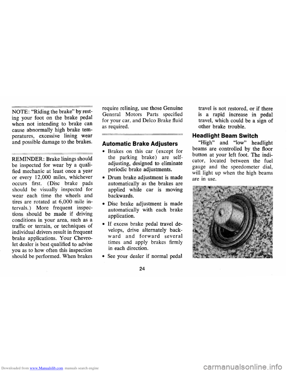
Headlight Beam Switch
"High" and "low" headlight
beams are controlled by the floor
button at your left foot. The indi
cator, located between the fuel
gauge and the speedometer dial
will light
up when the high beam~
are in use.
Page 27 of 86
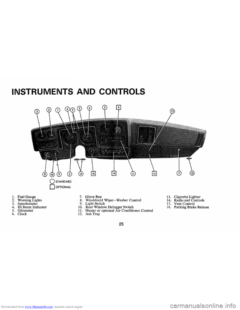
Downloaded from www.Manualslib.com manuals search engine INSTRUMENTS AND CONTROLS
o STANDARD
o OPTIONAL
1. Fuel Gauge 7. GloveBox 13. Cigarette Lighter
2. Warn ing Lights 8. Windshield Wiper-Washer Control
14. Radio and Controls 3. Speedometer 9. Light Switch 15. Vent Control 4. Hi Beam Indicator 10. Rear Window Defogger Switch 16. Parking Brake Release 5. Odometer 11. Heater or optional Air Conditioner Control 6. Clock 12. Ash Tray
25