check engine CHEVROLET MONTE CARLO 1973 2.G Owners Manual
[x] Cancel search | Manufacturer: CHEVROLET, Model Year: 1973, Model line: MONTE CARLO, Model: CHEVROLET MONTE CARLO 1973 2.GPages: 86, PDF Size: 33.46 MB
Page 5 of 86
Downloaded from www.Manualslib.com manuals search engine BEFORE DRIVING YOUR MONTE CARLO
DRIVER CHECKLIST
Before Entering Car
1. See that windows , mirrors and
lights are clean.
2 . Visually note inflation condition
of tires.
3. Check that area to rear is clear
if about to back up.
Before Driving Off
1. Lock all doors.
2. Position seat and adjust head
restraints.
3. Adjust inside and outside mir
rors.
4 . Fasten seat belts.
5. Check that warning bulbs light
when key
is turned to start posi
tion.
6 . Release parking brake (and see
that brake warning light turns
off). 7
. Be sure you understand your
car and how to operate it safely.
Keys
Two separate keys are provided
for your car. Each key has a differ
ent cross section so that it can be
inserted only
in certain locks.
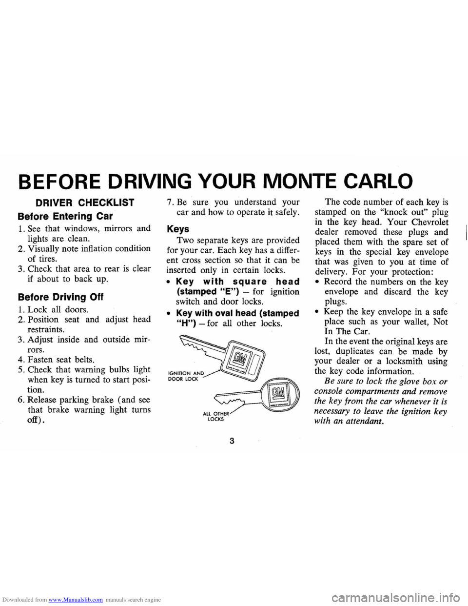
• Key with square head
(stamped "E") -for ignition
switch and door locks.
• Key with oval head (stamped
"H") -for all other locks.
fib
~ ALL OTHER LOCKS
3
The code number of each key is
stamped on the "knock out" plug
in the key head. Your Chevrolet
dealer removed these plugs and
placed them with the spare set of
keys in the special key envelope
that was given to you at time of
delivery. For your protection:
• Record the numbers on the key
envelope and discard the key
plugs.
• Keep the key envelope in a safe
place such
as your wallet, Not
In The Car.
In the event the original keys are
lost, duplicates can be made by
your dealer or a locksmith using
the key code information.
Be sure to lock the glove box or
console compartments and remove
the key from the car whenever it
is
necessary to leave the ignition key
with an attendant.
Page 11 of 86
Downloaded from www.Manualslib.com manuals search engine • To fasten the shoulder belt, un
stow it and place the knob on
the shoulder belt end in the
keyhole on the lap belt latch
plate. (The latch
is designed so
that this attachment can only be
completed before fastening the
lap belt.) Tilt the knob as neces
sary, to pass
it through the slot.
Pull the knob firmly upward to
seat it at the narrow end of the
keyhole, then fasten the lap belt.
• Shoulder belts are lengthened
and shortened in the same man
ner
as center seat lap belts.
• Shoulder belt should have suf
ficient slack to insert a fist's
width between your chest and
the belt. This can be checked
by inserting a clenched
fist be
tween the belt and your chest
with thumb against chest and
back of hand facing upward.
• When not in use, the shoulder
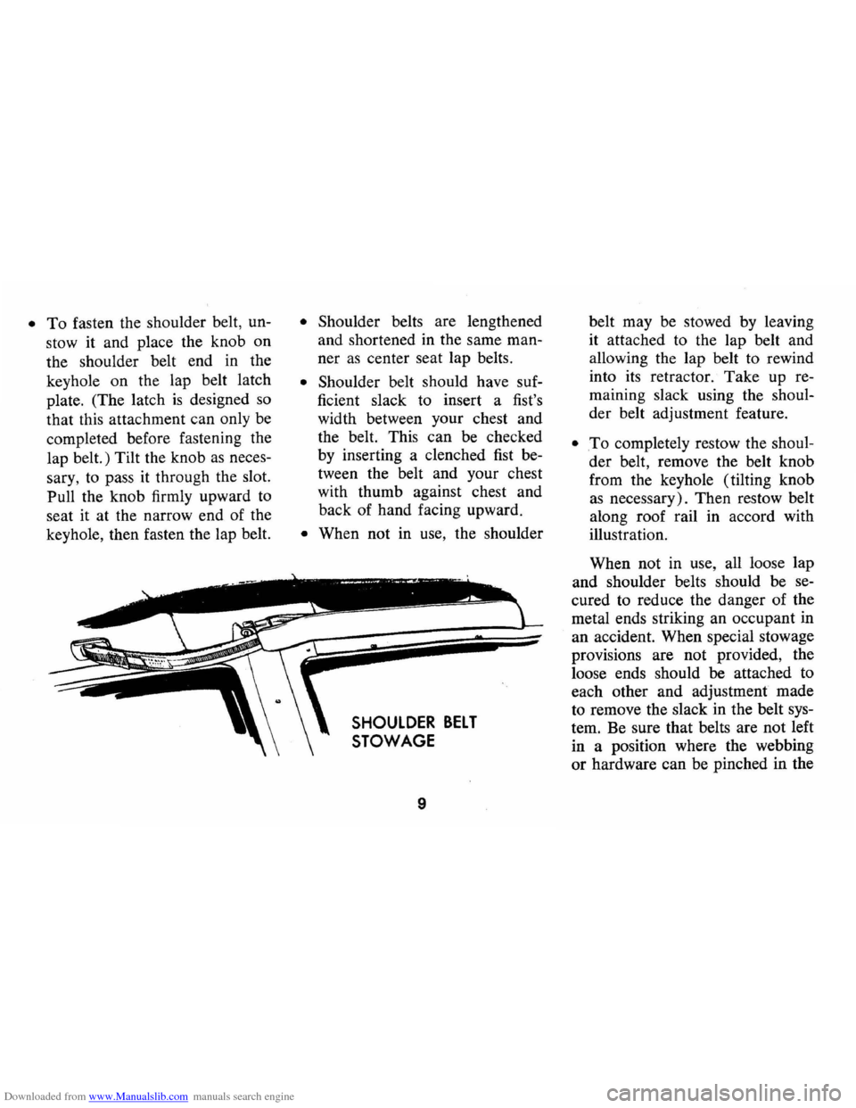
SHOULDER BELT
STOWAGE
9
belt may be stowed by leaving
it attached to the lap belt and
allowing the lap belt to rewind
into its retractor.
Take up re
maining slack using the shoul
der belt adjustment feature.
• .To completely restow the shoul
der belt, remove the belt knob
from the keyhole (tilting knob
as necessary). Then restow belt
along roof rail in accord with
illustration.
When not in use, all loose lap
and shoulder belts should be se
cured to reduce the danger of the
metal ends striking an occupant in
an accident. When special stowage
provisions are not provided, the
loose ends should be attached to
each other and adjustment made
to remove the slack in the belt sys
tem. Be sure that belts are not left
in a position where the webbing
or hardware can be pinched in the
Page 12 of 86
Downloaded from www.Manualslib.com manuals search engine seat structure or door, and thus
become damaged.
Seat Belt Inspection
• Periodically inspect belts, buck
les, retractors , and anchors for
damage that could lessen the
effectiveness of the restraint
system.
• Keep sharp edges and damaging
objects away from belts.
• Replace belts if cut, weakened,
frayed ,
or subjected to collision
loads.
• Check that anchor mounting
bolts are tight.
• Have questionable parts re
placed.
• Keep seat belts clean and dry.
• Clean only with mild soap solu
tion
and lukewarm water.
• Do not bleach or dye belts since
this may severely weaken belts.
Head Restraints
• Head restraints are designed to
help reduce injuries due to
"whiplash ."
• Select
one of the three positions
-full up, intermediate , or full
down-which places the top of
the head restraint closest to the
top of your ears.
• Do not use head restraint above
the full up
"detent" position.
• Head restraint can be raised by
pulling up until you feel it click
into the
"detent" at the inter
mediate position.
• To raise further, or to lower,
release latch at base of support
ing rod and push up
or down on
restraint.
• Do not operate vehicle with head
restraints removed, since occu
pants lose the protection pro
vided.
10
Child Restraint
Children in automobiles should
be restrained to lessen the risk of
injury in accidents, sudden stops
or other hazardous situations. Gen
eral motors dealers offer restraint
systems designed specifically for
use with infants.
In using any in
fant
or child restraint system, read
. and comply with all installation
'and usage instructions.
All unused seat belts near the
child should be stowed properly
to help prevent them from striking
him in the event of an accident.
Lap belts and shoulder belts with
out stowage provisions should
have buckles latched and belts
adjusted to remove slack.
Cars Not Equipped With
Special Child Restraints
If a child is traveling in a ve
hicle not equipped with a General
Motors infant restraint
or other
Page 14 of 86
Downloaded from www.Manualslib.com manuals search engine Detroit, Michigan 48202 (or in
Canada by writing to General
Moto rs of Canada Limited,
Owner
Relations Department , Oshawa,
Ontario) .
To assist in attaining good han
dling of the car-trailer combina
tion, it
is important that the trailer
tongue load be maintained at ap
proximately
10% of the loaded
trailer weight. Tongue loads can be
adjusted by proper distribution of
the load in the trailer, and can be
checked by weighing separately the
loaded trailer and then the tongue.
When towing trailers, tires
should be inflated to the highest inflation
pressures shown on the
placard affixed to the left front
door . The allowable passenger and
cargo load, also shown on the same
placard ,
is reduced by an amount
equal to
the trailer tongue load on
the trailer hitch.
Maintenance
More frequent vehicle mainte
nance
is required when using your
car to pull a trailer. Change the:
• Automatic transmission fluid
each
12 ,000 miles ,
• Rear axle fluid each 12,000
miles,
• Engine oil each 60 days or 3,000
12
miles , whichever occurs first.
• Positive crankcase ventilation
valve each 12 months or
12,000
miles, whichever occurs first.
Break-in Schedule
In addition to the new ca r
break-in instructions in this man
ual, it
is recommended that your
new Monte Carlo be operated for
500 miles before trailer towing. If
it is necessary to tow during this
period , avoid speeds over
50 MPH
and full throttle starts. The same
precautions should be observed
whenever a new engine, transmis
sion or axle
is installed in your car.
Page 22 of 86
Downloaded from www.Manualslib.com manuals search engine Turn Signal and Lane
. Change Features
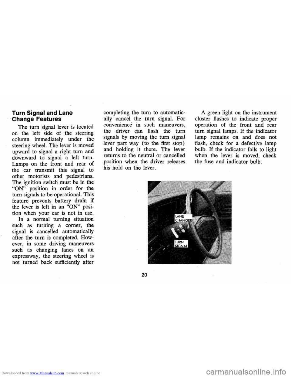
The tum signal lever is located
on the left side of the steering
column immediately under the
steering wheel. The lever
is moved
upward to signal a right
tum and
downward to signal a left tum.
Lamps on the front and rear of
the car transmit this signal to
other motorists and pedestrians.
The ignition switch must be in the
"ON" position in order for the
turn signals to be operational. This
feature prevents battery drain if
the lever
is left in an "ON" posi
tion when your car
is not in use.
In a normal turning situation
such
as turning a comer, the
signal
is cancelled automatically
after the tum
is completed. How
ever, in some driving maneuvers
such
as changing lanes on an
expressway, the steering wheel
is
not turned back sufficiently after completing
the
tum to automatic
ally cancel the turn signal.
For
convenience in such maneuvers,
the driver can flash the
tum
signals by moving the tum signal
lever part way (to the first stop)
and holding it there. The lever
returns to the neutral
or cancelled
position when the driver releases
his hold on the lever.
20
A green light on the instrument
cluster flashes to indicate proper
operation of the front and rear
tum signal lamps. If the indicator
lamp remains on and does not
flash, check for a defective lamp
bulb.
If the indicator fails to light
when the lever
is moved, check
the fuse and indicator bulb.
Page 25 of 86
Downloaded from www.Manualslib.com manuals search engine FLOOR CONTROLS
Braking System
The service brake system is de
signed for braking performance
under a wide range of driving con
ditions even when the vehicle
is
loaded to its full rated vehicle load.
Power Brakes
• On cars with power brakes if
power assist to the brakes
is
interrupted due to a stalled en
gine
or some malfunction, two
or more brake applications can
be made using reverse power.
• If the brake pedal is held down ,
the system
is designed to bring
the car to a full stop on reserve
power. However, the reserve
power
is partially depleted each
time the brake pedal
is applied
and released.
• When reserve power is ex- hausted,
the vehicle can still be
stopped by applying greater
force to the pedal.
Parking Brake
• To set parking brake, fully de
press foot pedal at far left side.
• For maximum holding power,
depress regular brake pedal with
the other foot at the same time.
• To release parking brake, pull
"BRAKE RELEASE" lever on
lower left instrument panel.
• As a reminder, the brake system
warning light
is designed to glow
whenever the parking brake con
trol
is not fully released, and the
ignition
is on.
• Never drive car with parking
brake set
as this may overheat
or otherwise damage rear brakes.
23
Clutch Adjustment
Clut8h adjustment should be
checked and adjusted periodically
as necessary to compensate for
clutch facing wear.
To check, de
press pedal by hand until resist
ance
is felt. Free travel of pedal
should be approximately one inch;
if very little
or no free travel is
evident, clutch adjustment is re
quired.
Page 29 of 86
Downloaded from www.Manualslib.com manuals search engine Generator Indicator Light
This light provides a quick
check on the generating system
of your car. The red light will
go on when the ignition key
is
in the "on" position, but before
the engine
is started. After the
engine starts, the light should go
out and remain out.
If the light
remains on when engine
is run
ning , have your Authorized Chev
rolet Dealer locate and correct
the trouble
as soon as possible.
Engine Temperature
Indicator Light
This indicator light is provided
in the
instrument cluster to
quickly warn of an overheated
engine. With the ignition switch
in the
START position, the red
TEMP indicator will light to let
you know that it
is operating
properly. When the engine
is started, the red
light will go out immediately.
It will light up at no other time
unless for some reason the engine
reaches a dangerously high oper
ating temperature.
If the red light
should come on, the engine must
be stopped until the cause of the
overheating
is corrected. Glance
at instrument cluster frequently
as
you drive to see if this light is on.
Brake System Warning Light
The service brake system is
designed so that half of the brake
system will provide some braking
action in the event of a hydraulic
leak in the other half of the
sys
tem. If the warning light located
below the fuel gauge glows con
tinuously when the ignition
is on
and after the brakes have been
firmly applied, it may indicate that
there
is a malfunction in one half
of the brake hydraulic system.
27
• As a check on bulb condition
the light should glow with the
parking brake applied and the
ignition on. (Light
is also a
reminder to release parking
brake) .
• Have system repaired if light
does not come on during check.
• This warning light is not a sub
stitute for the visual check of
brake fluid level required
as
part of normal maintenance.
If the light glows red:
• The parking brake control is not
fully released or,
• The service brake system is
partially inoperative
What to do:
1. Check that the parking brake
is released. If it is ...
2. Pull off the road and stop,
carefully- remembering that:
Page 30 of 86
Downloaded from www.Manualslib.com manuals search engine • Stopping distances may be
greater.
• Greater pedal effort may be
required .
• Pedal travel may be greater.
3.
Tryout braking operation by
starting and stopping on road
shoulder -then:
• If you judge such operation
to be safe , proceed cautious
ly
at a s afe speed to nearest
dealer for repair.
• Or have car towed to dealer
for repair.
Continued operation of the car
in this condition
is dangerous.
Headlight Beam Indicator
Light
The headlights of your car have
high and low beams to provide
ybu
with proper night-time visibility
for most driving conditons . The
"low" beams are used during most
city driving. The "high" beams are especially
useful when driving
on
dark roads since they provide ex
cellent long range illumination.
The headlight beam indicator will
be on whenever the high beams
or
"brights" are in use. The Headlight
Beam Switch controls the headlight
beams (see
Page 24).
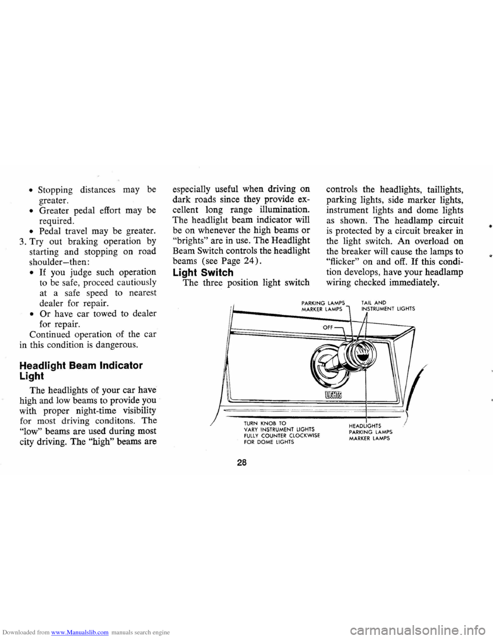
Light Switch
The three position light switch controls
the headlights, taillights,
parking lights, side marker lights,
instrument lights and dome lights
as shown. The headlamp circuit
is protected by a circuit breaker in
the light switch. An overload on
the breaker will cause the lamps to
"flicker" on and off. If this condi
tion develops, have your headlamp
wiring checked immediately.
PARKING LAMPS MARKER LAMPS TAIL AND INSTRUMENT LIGHTS
--,---.---~------ -- --------
TURN KNOB TO VARY INSTRUMENT LIGHTS fULLY COUNTER CLOCKWISE fOR DOME LIGHTS
28
HEADLIGHTS PARKING LAMPS MARKER LAMPS
•
Page 33 of 86
Downloaded from www.Manualslib.com manuals search engine Clock
Reset the clock , by pulling out
the knob and turning the hands
clockwise
if slow, counterclockwise
if fast. This will, if the clock error
is five minutes or more, automati
cally compensate for time gain or
lag . Several resettings, several days
apart, may be needed to propertly
adjust the clock mechanism. Have
your clock cleaned and oiled by a
competent clock serviceman at
least every two years.
Cigarette Lighter
The cigarette lighter is located
on the instrument panel face.
To
operate, push it in. When it be
comes heated, it automatically pops
out ready for use.
Windshield Wiper and
Washer
The windshield wiping system
operates at two speeds and
is de
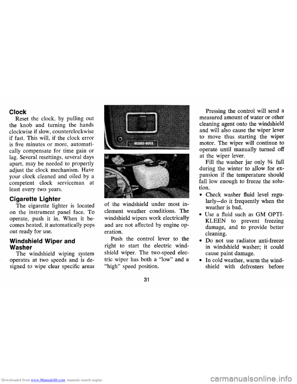
signed to wipe clear specific areas of
the windshield under most in
clement weather conditions . The
windshield wipers work electrically
and are not affected by engine op
eration. Push the control lever to the
right to start the electric wind
shield wiper. The two-speed elec
tric wiper has both a "low" and a
"high" speed position.
31
Pressing the control will send a
measured amount of water or other
cleaning agent onto the windshield
and will also cause the wiper lever
to move thus starting the wiper
motor. The wiper will continue to
operate until manually turned off
at the wiper lever.
Fill the washer jar only
% full
during the winter to allow for ex
pansion if the temperature should
fall low enough to freeze the solu
tion .
• Check washer fluid level regu
larly-do it frequently when the
weather is bad .
• Use a fluid such as GM OPTI
KLEEN to prevent freezing
damage, and to provide better
cleaning.
• Do not use radiator anti-freeze
in windshield washer; it could
cause paint damage.
• In cold weather, warm the wind
shield with defrosters before
Page 45 of 86
Downloaded from www.Manualslib.com manuals search engine or property damage. All General
Motors cars have negative-ground
electrical systems and can be used
to jump start one another.
If you
cannot determine how the other
vehicle
is grounded (by checking
specifications in the owner's man
ual, etc.) we recommend that you
attempt no jump starting with that
vehicle.
Jump Starting with
Auxiliary (Booster) Battery
Both booster and discharged
battery should be treated carefully
when using jumper cables. Follow
exactly the procedure outlined be
low, being careful not to cause
sparks:
1.
Set parking brake and place
automatic transmission in
"PARK" (neutral for manual
transmission).
Turn off lights,
heater and other electrical loads. 2.
Remove vent caps from both
the booster and the discharged
batteries. Lay a cloth over the
open vent wells of each battery.
These two actions help reduce
the explosion hazard always
present in either battery when
connecting
"live" booster bat
teries to
"dead" batteries.
3. Attach one end of one jumper
cable to the positive terminal of
the booster battery (identified
by a red color,
"+" or "P" on
the battery case, post or clamp)
and the other end of same cable
to positive terminal of discharged
battery. Do
NOT permit cars to
touch each other,
as this could
'establish a ground connection
and counteract the benefits of
this procedure.
4. Attach one end of the remaining
negative cable to the negative
terminal (black color,
"-" or
"N") of the booster battery, and
43
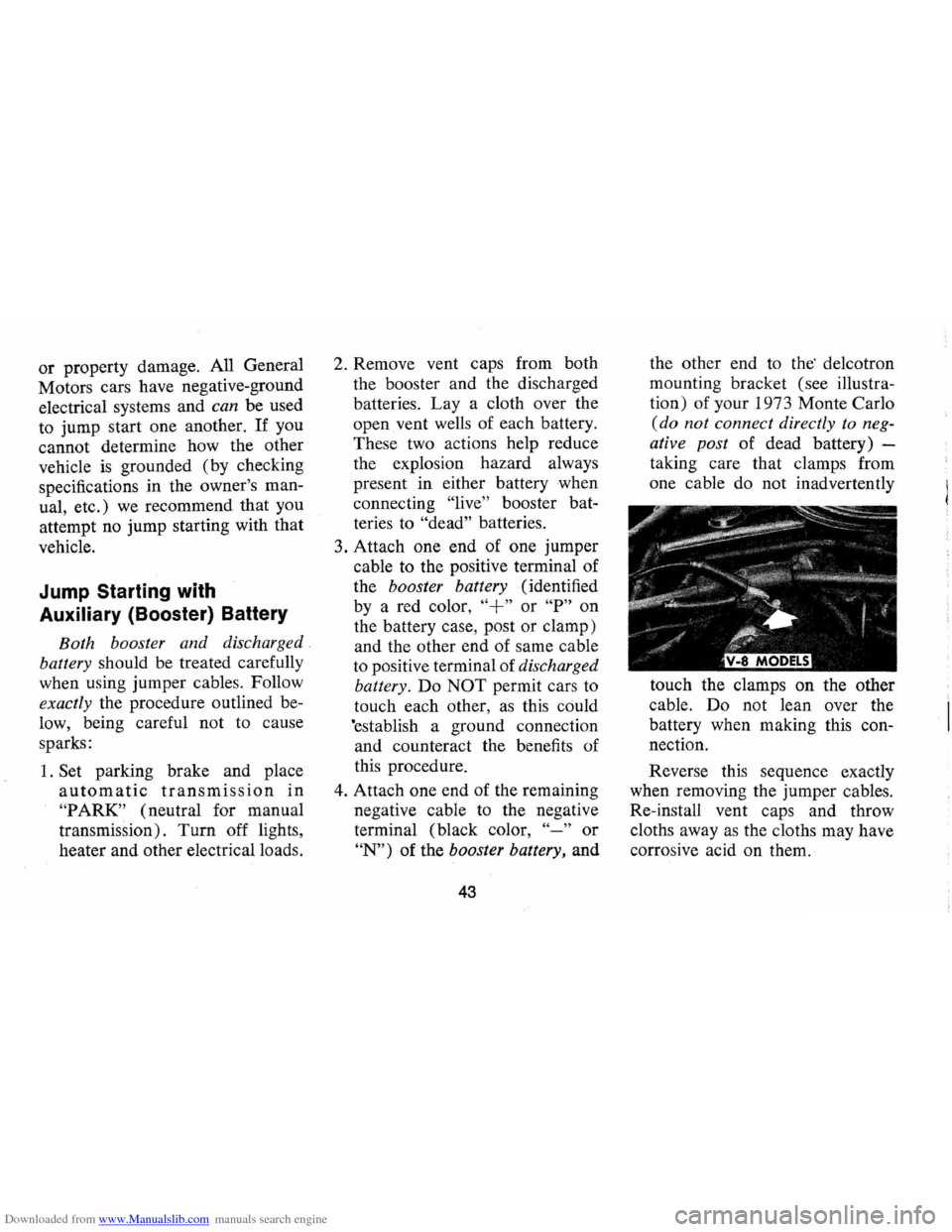
the other end to the' de1cotron
mounting bracket (see illustra
tion) of your 1973 Monte Carlo
(do not connect directly to neg
ative post of dead battery) -
taking care that clamps from
one cable do not inadvertently
touch the clamps on the other
cable. Do not lean over the
battery when making this con
nection.
Reverse this sequence exactly
when removing the jumper cables.
Re-install vent caps and throw
cloths away
as the cloths may have
corrosive acid on them.