heater CHEVROLET MONTE CARLO 1973 2.G Owners Manual
[x] Cancel search | Manufacturer: CHEVROLET, Model Year: 1973, Model line: MONTE CARLO, Model: CHEVROLET MONTE CARLO 1973 2.GPages: 86, PDF Size: 33.46 MB
Page 27 of 86
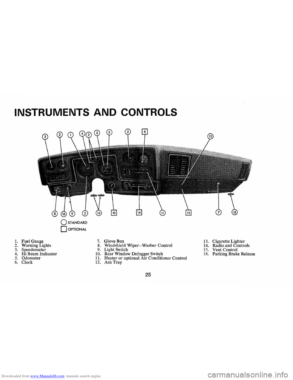
Downloaded from www.Manualslib.com manuals search engine INSTRUMENTS AND CONTROLS
o STANDARD
o OPTIONAL
1. Fuel Gauge 7. GloveBox 13. Cigarette Lighter
2. Warn ing Lights 8. Windshield Wiper-Washer Control
14. Radio and Controls 3. Speedometer 9. Light Switch 15. Vent Control 4. Hi Beam Indicator 10. Rear Window Defogger Switch 16. Parking Brake Release 5. Odometer 11. Heater or optional Air Conditioner Control 6. Clock 12. Ash Tray
25
Page 34 of 86
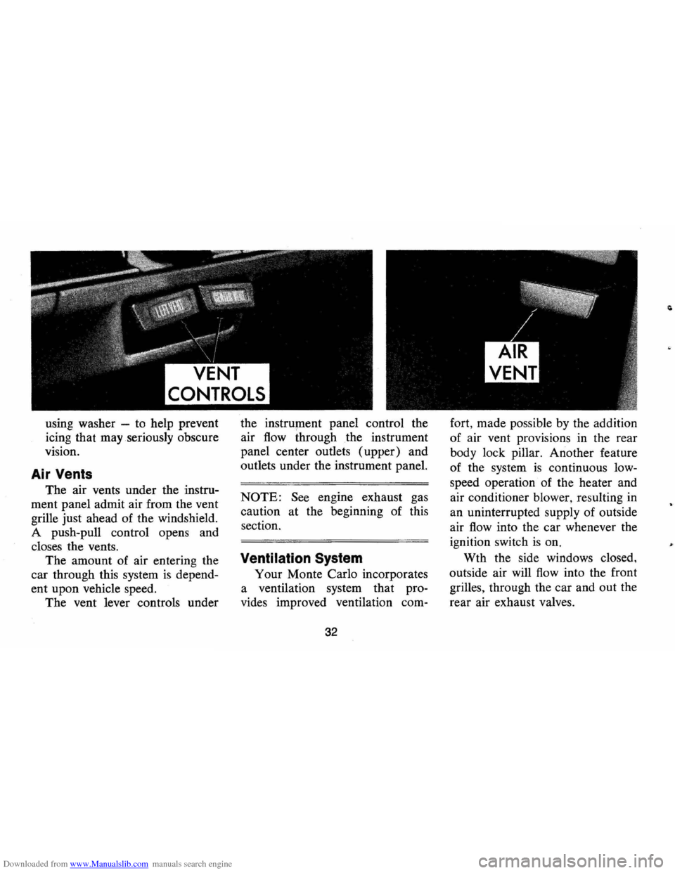
Downloaded from www.Manualslib.com manuals search engine VENT
CONTROLS
using washer -to help prevent
icing that may seriously obscure
vision.
Air Vents
The air vents under the instru
ment panel admit air from the vent
grille just ahead of the windshield.
A push-pull control opens and
closes the vents.
The amount of air entering the
car through this system
is depend
ent upon vehicle speed.
The vent lever controls under the
instrument panel control the
air
flow through the instrument
panel center outlets (upper) and
outlets under the instrument panel.
NOTE: See engine exhaust gas
caution at the beginning of this
section.
Ventilation System
Your Monte Carlo incorporates
a ventilation system that pro
vides improved ventilation com-
32
fort, made possible by the addition
of air vent provisions in the rear
body lock pillar. Another feature
of the system
is continuous low
speed operation of the heater and
air conditioner blower, resulting
in
an uninterrupted supply of outside
air
flow into the car whenever the
ignition switch
is on.
Wth the side windows closed,
outside air will
flow into the front
grilles, through the car and out the
rear air exhaust valves.
Page 36 of 86
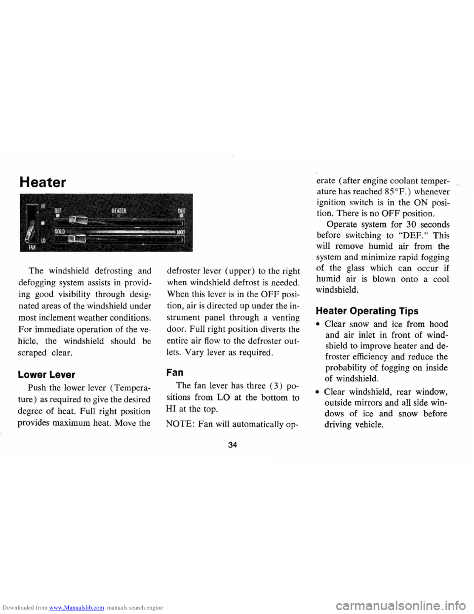
Downloaded from www.Manualslib.com manuals search engine Heater
The windshield defrosting and
defogging system assists in provid
ing good visibility through desig
nated areas of the windshield under
most inclement weather conditions.
For immediate operation of the ve
hicle , the windshield should be
scraped clear.
Lower Lever
Push the lower lever (Tempera
ture)
as required to give the desired
degree of heat. Full right position
provides maximum heat. Move the defroster
lever (upper) to the right
when windshield defrost
is needed.
When this lever
is in the OFF posi
tion , air
is directed up under the in
strument panel through a venting
door. Full right position diverts the
entire air
flow to the defroster out
lets. Vary lever
as required.
Fan
The fan lever has three (3) po
sitions from
LO at the bottom to
HI at the top.
NOTE: Fan will automatically op-
34
erate (after engine coolant temper- /,
ature has reached 85°
F.) whenever
ignition switch
is in the ON posi
tion. There
is no OFF position.
Operate system for
30 seconds
before switching to
"DEF." This
will remove humid air from the
system and minimize rapid fogging
of the glass which
can occur if
humid air
is blown onto a cool
windshield.
Heater Operating Tips
• Clear snow and ice from hood
and air inlet in front of wind
shield to improve heater and de
froster efficiency and reduce the
probability of fogging on inside
of windshield.
• Clear windshield, rear window,
outside mirrors and all side win
dows
of ice and snow before
driving vehicle.
Page 37 of 86
Downloaded from www.Manualslib.com manuals search engine • Operate blower on "HIGH" for
a
few seconds before moving the
vehicle, to clear the intake ducts
of snow.
• Keep all windows and vents
closed to reduce dust, road and
wind noise and uncomfortable
drafts.
• For most satisfactory heater op
eration and air circulation, op
erate fan on low
or medium
speeds for normal operation and
high speed for quick warm-up
and during extremely low temp
eratures.
• For adequate rear seat heating,
the area beneath the front seat
must not be blocked
by carpet
ing, rags, paper or other ma
terial and fan should operate on
high blower.
Rear Window Defroster
To ensure clear vision through
the rear window during inclement weather,
the Rear Window De
froster
is optionally available. This
unit draws
in air from the pas
senger compartment and directs it against
the back window to remove
frost or moisture. Its blower has a
two-speed control switch on the
instrument panel.
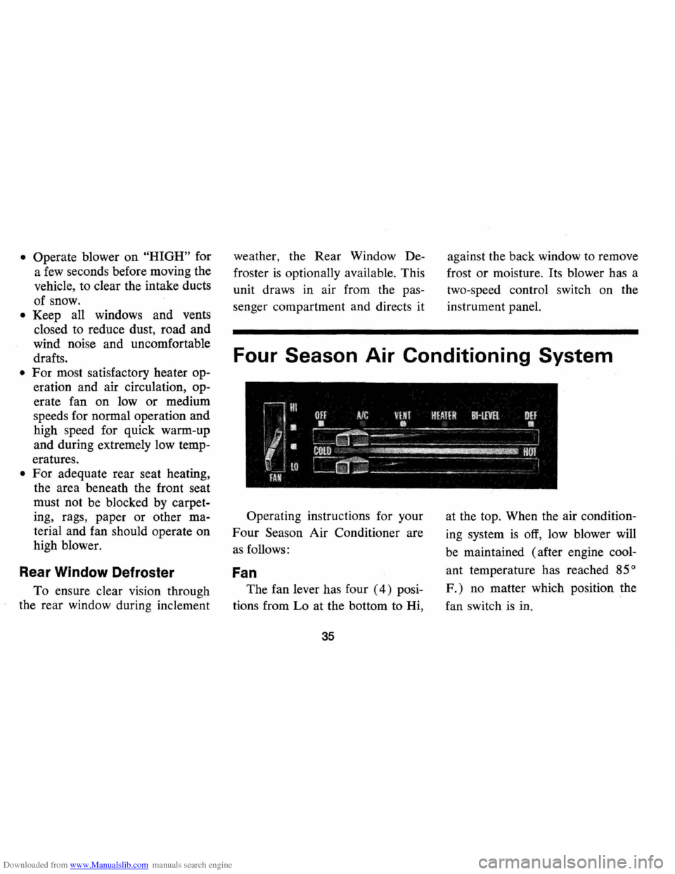
Four Season Air Conditioning System
Operating instructions for your
Four Season Air Conditioner are
as follows:
Fan
The fan lever has four (4) posi
tions from Lo at the bottom to Hi,
35
at the top. When the air condition
ing system
is off, low blower will
be maintained (after engine cool
ant temperature has reached
85°
F.) no matter which position the
fan switch
is in.
Page 38 of 86
Downloaded from www.Manualslib.com manuals search engine Temperature (Lower Lever)
The temperature lever allows a
selection of air temperature from
Cold at the far left to Hot
at the far
right. When the temperature lever
is in the COLD position the system
will provide the coldest air possible.
When the temperature lever
is
moved to the right (toward HOT) ,
the system will operate on outside
air.
Selector (Upper Lever)
This lever provides a selection of
systems available to handle various
heating and cooling requirements
throughout the year. The Selector
lever has four
(4) major opera
tional
positions-"Off," "Air Condi
tioning," "Vent" and "Heating."
The "Air Conditioning" and "Heat
ing"
groups have several positions
which improve the effectiveness of the
system for various demands.
OFF-The system operates on low
blower regardless of fan switch po
sition with air discharged into
ve
hicle through heater outlet.
A/C-Air from the passenger com
partment
is recirculated through
the system with some outside air
and discharged from the upper out
lets when the temperature lever
is
in Full COLD or extreme left. If
the Temperature lever is moved
right to the first stop or further, the
system will automatically go on
outside air. The
AIC position, with
Temp. lever in Full
COLD, is used
when maximum cooling
is required
under conditions of high tempera
ture and humidity. High fan speed
is automatically attained in this
position .
36
A/C (with Temp lever right to first
stop) -Outside air
is passed
through the system and discharged
through the upper outlets. This po
sition
is recommended for most air
conditioning situations because of
reduced blower noise and reduction
of cigarette smdke within the
ve
hicle. Fan speed may be varied as
required.
VENT -Outside air is passed
through the system and discharged
from the upper and lower outlets.
This position
is provided for cool
to moderate weather when refrig
eration
is not required.
HEATER-Outside air
is delivered
through the heater outlet and with
some air through the defroster out
lets. Temperature may be adjusted
as required. This position is recom-
Page 39 of 86
Downloaded from www.Manualslib.com manuals search engine mended for most winter driving.
BI-LEVEL -Outside air is deliv
ered from the heater lower outlet
and the defroster duct and upper
outlets to provide comfort and keep
the windshield and side glass clear
under low fogging conditions.
DEF -Outside air is delivered
through the defroster outlets only.
Temperature and blower speeds
may be adjusted
as required. This
position
is recommended for condi
tions of severe fogging and icing
only.
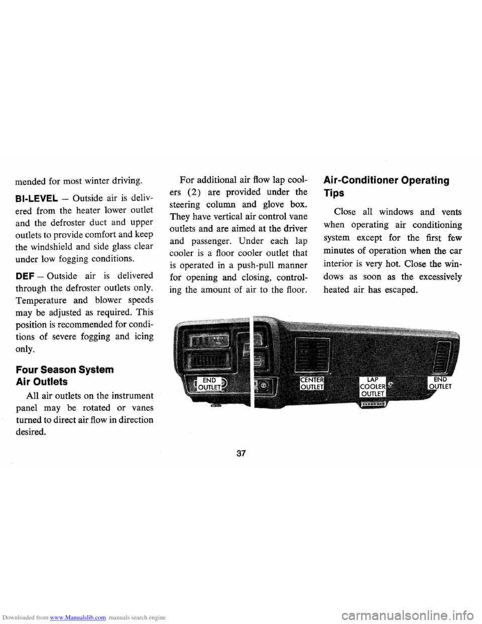
Four Season System
Air
Outlets
All air outlets on the instrument
panel may be rotated
or vanes
turned to direct air
flow in direction
desired.
For additional air flow lap cool
ers
(2) are provided under the
steering column and glove box.
They have vertical air control vane
outlets and are aimed at the driver
and passenger. Under each lap
cooler
is a floor cooler outlet that
is operated in a push-pull manner
for opening and closing, control
ing the amount of air to the floor.
37
Air-Conditioner Operating
Tips
Close all windows and vents
when operating air conditioning
system except for the first
few
minutes of operation when the car
interior
is very hot. Close the win
dows
as soon as the excessively
heated air has escaped.
Page 45 of 86
Downloaded from www.Manualslib.com manuals search engine or property damage. All General
Motors cars have negative-ground
electrical systems and can be used
to jump start one another.
If you
cannot determine how the other
vehicle
is grounded (by checking
specifications in the owner's man
ual, etc.) we recommend that you
attempt no jump starting with that
vehicle.
Jump Starting with
Auxiliary (Booster) Battery
Both booster and discharged
battery should be treated carefully
when using jumper cables. Follow
exactly the procedure outlined be
low, being careful not to cause
sparks:
1.
Set parking brake and place
automatic transmission in
"PARK" (neutral for manual
transmission).
Turn off lights,
heater and other electrical loads. 2.
Remove vent caps from both
the booster and the discharged
batteries. Lay a cloth over the
open vent wells of each battery.
These two actions help reduce
the explosion hazard always
present in either battery when
connecting
"live" booster bat
teries to
"dead" batteries.
3. Attach one end of one jumper
cable to the positive terminal of
the booster battery (identified
by a red color,
"+" or "P" on
the battery case, post or clamp)
and the other end of same cable
to positive terminal of discharged
battery. Do
NOT permit cars to
touch each other,
as this could
'establish a ground connection
and counteract the benefits of
this procedure.
4. Attach one end of the remaining
negative cable to the negative
terminal (black color,
"-" or
"N") of the booster battery, and
43
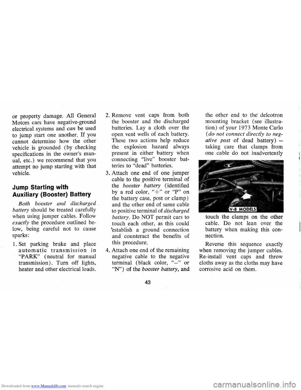
the other end to the' de1cotron
mounting bracket (see illustra
tion) of your 1973 Monte Carlo
(do not connect directly to neg
ative post of dead battery) -
taking care that clamps from
one cable do not inadvertently
touch the clamps on the other
cable. Do not lean over the
battery when making this con
nection.
Reverse this sequence exactly
when removing the jumper cables.
Re-install vent caps and throw
cloths away
as the cloths may have
corrosive acid on them.
Page 76 of 86
Downloaded from www.Manualslib.com manuals search engine FUSES AND CIRCUIT BREAKER:
The headlamp circuit is protected by a circuit breaker in the light switch. An electrical overload on the breaker will cause the lamps to go on and
off, or in some cases to remain off. If this condition develops, have your
wiring circuits checked immediately. Also, a circuit breaker, mounted on the firewall, protects the power window and power seat circuits if vehicle is so equipped. Where current load is too heavy, the circuit breaker
intermittently opens and closes, protecting the circuit until the cause is found and eliminated.
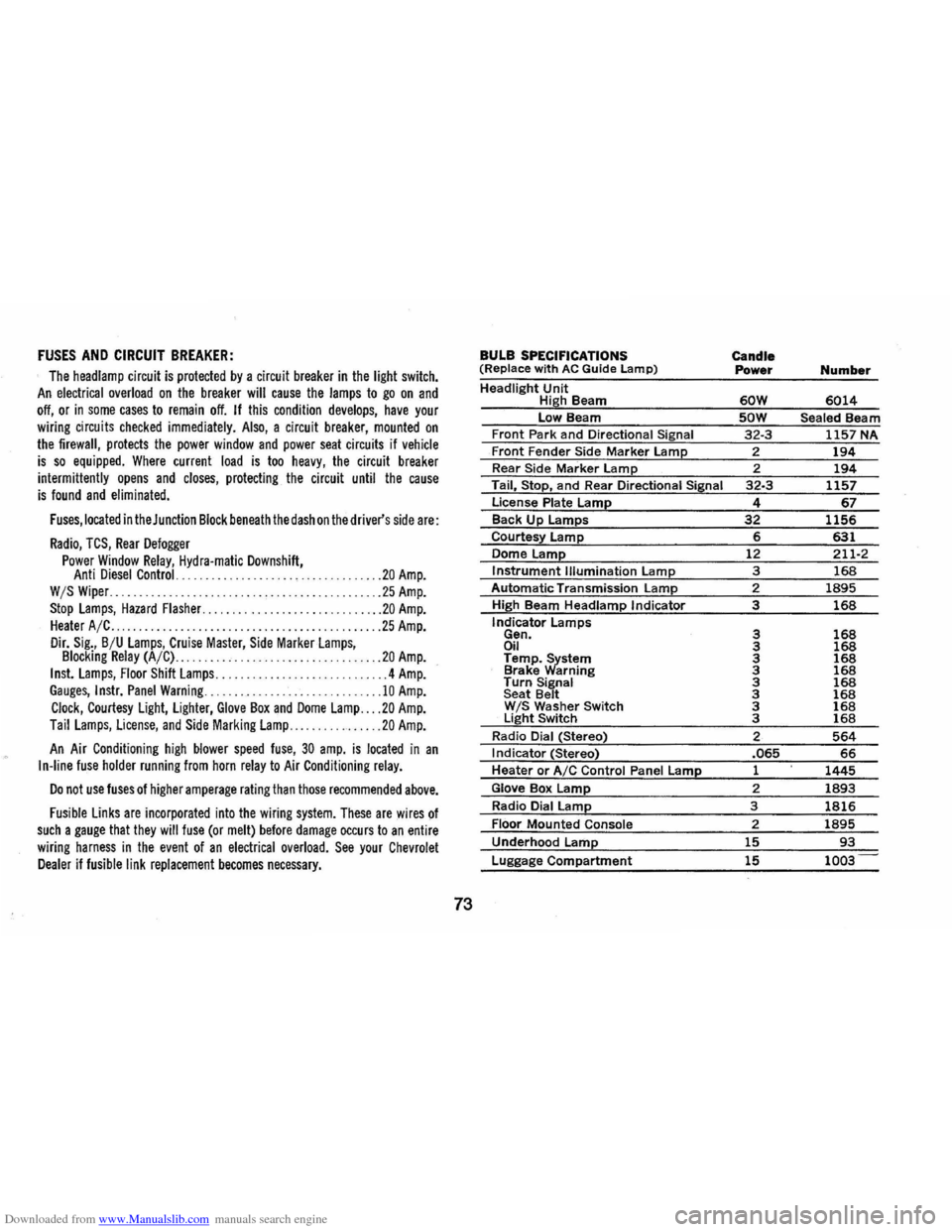
Fuses, located in the Junction Block beneath the dash on the driver's side are:
Radio, TCS, Rear Defogger
Power Window Relay, Hydra-matic Downshift, Anti Diesel Control. .... .. ................ ... ... .... .. 20 Amp. W /S Wiper. ... .......................................... 25 Amp.
Stop Lamps, Hazard Flasher .............................. 20 Amp. Heater A/C . . . . . . . . . .. . ..... ............................ 25 Amp.
Dir. Sig., B /U Lamps, Cruise Master, Side MarkerLamps, Blocking Relay (A/C) ............... .. .. .............. .. 20 Amp.
Inst. Lamps, Floor Shift Lamps ....... .... .. .... ............ 4 Amp. Gauges, Instr. Panel Warning .............................. 10 Amp.
Clock, Courtesy Light, Lighter, Glove Box and Dome Lamp ... . 20 Amp.
Tail Lamps, License, and Side Marking Lamp .............. .. 20 Amp.
An Air Conditioning high blower speed fuse, 30 amp. is located in an I n-line fuse holder running from horn relay to Air Conditioning relay.
Do not use fuses of higher amperage rating than those recommended above.
Fusible Links are incorporated into the wiring system. These are wires of such a gauge that they will fuse (or melt) before damage occurs to an entire
wiring harness in the event of an electrical overload. See your Chevrolet Dealer if fusible link replacement becomes necessary.
73
BULB SPECIFICATIONS
(Replace w ith AC Guide Lamp)
Headlight Unit High Beam
low Beam Front Park and Directional Signal
Front Fender Side Marker lamp Rear Side Marker lamp
Tail, Stop, and Rear Directional Siinal
License Plate Lame Back Up lamps
Courtes~ lamp
Dome Lame Instrument Illumination lamp
Automatic Transmission Lamp
High Beam Headlamp Indicator
Indicator
lamps Gen. Oil Temp.~stem Brake arning Turn Signal
Seat Belt W IS Washer Switch light Switch
Radio Dial (Stereo)
I ndicator (Stereo)
Heater or AIC Control Panel lame
Glove Box lamp
Radio Dial lamp
Floor Mounted Console
Underhood lame
Luggage Compartment
Candle
Power Number
60W 6014
SOW Sealed Beam 32-3 1157 NA
2
194 2 194 32-3 1157
4 67 32 1156 6 631 12 211-2
3 168 2 1895
3 168
3 168 3 168 3 168 3 168 3 168 3 168 3 168 3 168
2 564 .065 66 1 1445
2 1893
3 1816
2 1895
15 93
15 1003
Page 83 of 86
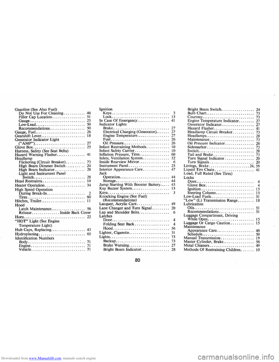
Downloaded from www.Manualslib.com manuals search engine Gasoline (See Also Fuel) Do Not Use For Cleaning ........... 46 Filler Cap Location. .. .. .. . . . .. .. ... 51 Gauge ............................. 25 Low-Lead .......................... 50 Recommendations. . . . . . . . . . . . . . . . .. 50 Gauge, Fuel.. . . . . . . . . . . . . . . . . . . . . . . .. 26 Gearshift Lever. . . . . . . . . . . . . . . . . . . . . .. 18 Generator Indicator Light ("AMP") .......................... 27 Glove Box. . . . . . . . . . . . . . . . . . . . . . . . . .. 25 Harness, Safety (See Seat Belts)
Hazard Warning Flasher. .............. 41 Headlamp
Flickering (Circuit Breaker). . . . . . . . .. 73 High Beam Dimmer Switch .......... 24 High Beam Indicator ........... ; . . .. 28 Light and Instrument Panel
Switch ........................... 28 Head Restraints . . . . . . . . . . . . . . . . . . . . .. 10 Heater Operation. . . . . . . . . . . . . . . . . . . .. 34 High Speed Operation
During Break-In.. .... .. .. .. .... .... 2
Tires .............................. 60 Hitches, Trailer... . . . . . . . . . . . . . . . . . . .. II
Hood Latch Maintenance
.................. 56 Release .............. Inside Back Cover
Horn ................................ 22 "HOT" Light (See Engine
Temperature Light)
Hub Caps, Replacing.. . . . . . . . . . . . . . . .. 43 Hydroplaning. . . . . . . . . . . . . . . . . . . . . . .. 65 Identification Numbers
Body ........................... : .. 71 Engine ............................ 71 Vehicle ............................ 71
Ignition Keys.................. ............ 3
Lock ..... ......................... 15 In Case Of Emergency. . . . . . . . . . . . . . . .. 41 Indicator Lights
Brake ................ ............. 27 Electrical Charging (Generator) ....... 27 Engine Temperature. . . . . . . . . . . . . . . .. 27 Fuel .............................. 26 Oil Pressure. . . . . . . . . . . . . . . . . . . . . . .. 26 Infant Restraining Methods. . . . . . . . . . .. 10 Infant Safety Carrier. . . . . . . . . . . . . . . . .. 10 Inflation Pressure, Tires. . . . . . . . . . . . . . .. 60 InIets, Ventilation System .............. 32 Inside Rearview Mirror. . . . . . . . . . . . . . . . 6
Instrument Panel. . . . . . . . . . . . . . . . . . . .. 25 Interior Appearance Care .............. 47 Jack
Operation .......................... 44 Storage .............. ............. , 44 Jump Starting With Booster Battery. . . .. 43 Key Buzzer System ....... , ............ 15 Keys................................ 3
Knocking Engine (See Fuel)
(Recommendations)
Lacquer, Acrylic Care .
................ 49 Lane Changer and Turn Signal. . . . . . . .. 20 Lap and Shoulder Belts... . . . . . . . . . . . . . 6
Latches
Door............. ................. 4
Folding Seat Back. . . . . . . . . . . . . . . . .. 4
Hood ................. ............ 56 Lighter, Cigarette ......... ............ 31 Lights ...................... , ........ 73 Backup ............................ 73 Brake Warning . . . . . . . . . . . . . . . . . . . .. 27 Bright Beam Indicator ............... 28
80
Bright Beam Switch .............. , .. 24 Bulb Chart. . . . . . . . . . . . . . . . . . . . . . . .. 73 Courtesy. . . . . . . . . . . . . . . . . . . . . . . . . .. 73 Engine Temperature Indicator. . . . . . .. 27 Generator Indicator. . . . . . . . . . . . . . . .. 27 Hazard Flasher. . . . . . . . . . . . . . . . . . . .. 41 Headlamp Circuit Breaker. . . . . . . . . .. 73 Headlamps. . . . . . . . . . . . . . . . . . . . . . . .. 28 Maintenance . . . . . . . . . . . . . . . . . . . . . .. 73 Oil Pressure Indicator. . . . . . . . . . . . . .. 26 Sidemarker. . . . . . . . . . . . . . . . . . . . . . .. 73 Switch ............................. 28 Tail and Brake. . . . . . . . . . . . . . . . . . . .. 73 Turn Signal Indicator. . . . . . . . . . . . . .. 20 Turn Signals. . . . . . . . . . . . . . . . . . . . . .. 20 Linings, Brake ..................... 24, 56 Liquid Tire Chain .................... 41 Load, Full Rated (See Tires)
Locks
Door......................... .. ... 4
Glove Box....... .................. 4
Ignition. . . . . . . . . . . . . . . . . . . . . . . . . .. 15 Steering Column .................... 15 Low-Lead Fuels ...................... 51 "Low" (L) Transmission Range ........ 18 Lubrication Oils ............................... 51 Recommendations. . . . . . . . . . . . . . . . .. 51 Luggage Compartment, Driving
While Open ........................ 15 Luggage Or Cargo Caution. . . . . . . . . . .. 15 Maintenance
Appearance Care. . . . . . . . . . . . . . . . . .. 46 Schedule. . . . . . . . . . . . . . . . . . . . . . . . . .. 50 Manual Transmission ................. 19 Master Cylinder, Brake. . . . . . . . . . . . . . .. 56 Metal Cleaners. . . . . . . . . . . . . . . . . . . . . .. 49 Methods Of Restraining Children ....... 10