CHEVROLET PLYMOUTH ACCLAIM 1993 Service Manual
Manufacturer: CHEVROLET, Model Year: 1993, Model line: PLYMOUTH ACCLAIM, Model: CHEVROLET PLYMOUTH ACCLAIM 1993Pages: 2438, PDF Size: 74.98 MB
Page 1601 of 2438
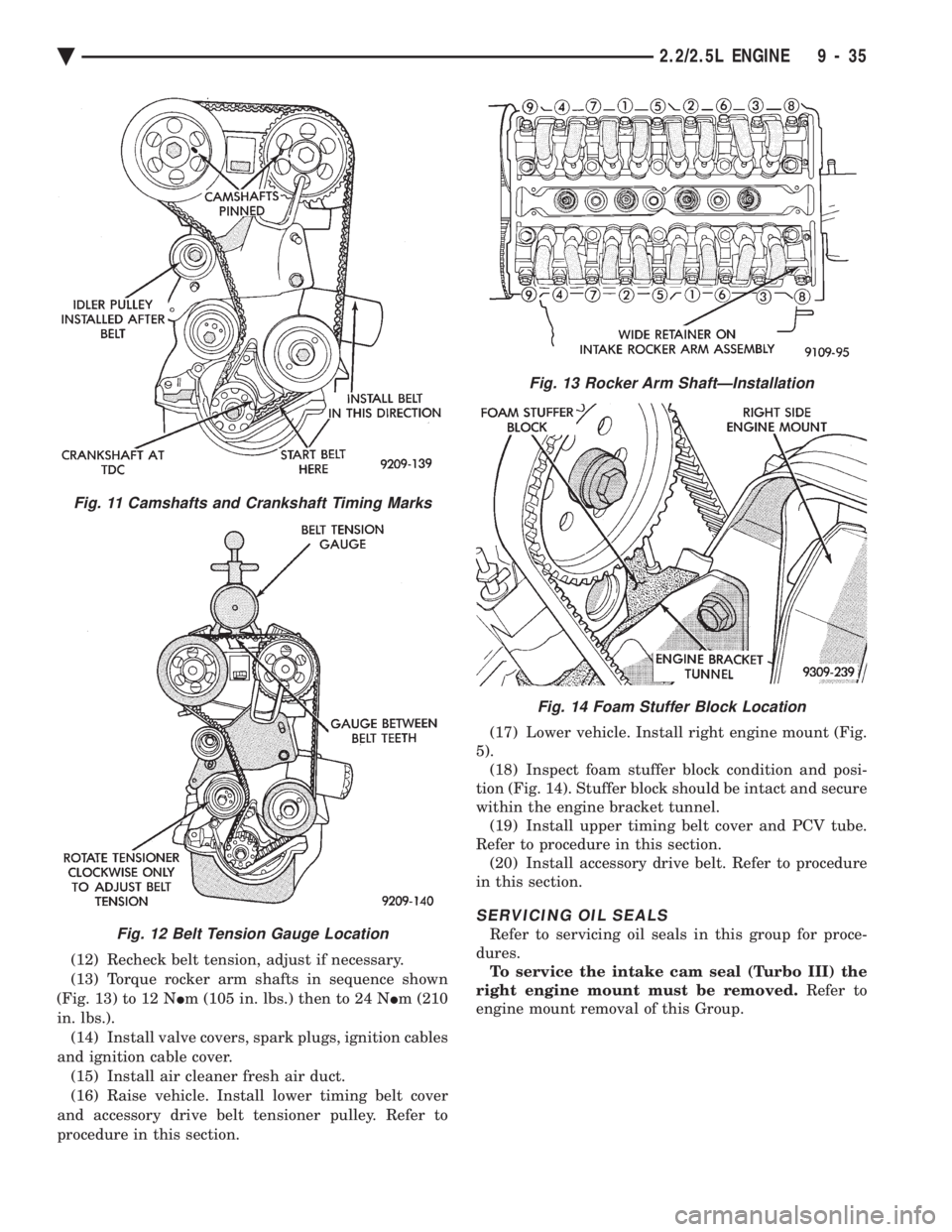
(12) Recheck belt tension, adjust if necessary.
(13) Torque rocker arm shafts in sequence shown
(Fig. 13) to 12 N Im (105 in. lbs.) then to 24 N Im (210
in. lbs.). (14) Install valve covers, spark plugs, ignition cables
and ignition cable cover. (15) Install air cleaner fresh air duct.
(16) Raise vehicle. Install lower timing belt cover
and accessory drive belt tensioner pulley. Refer to
procedure in this section. (17) Lower vehicle. Install right engine mount (Fig.
5). (18) Inspect foam stuffer block condition and posi-
tion (Fig. 14). Stuffer block should be intact and secure
within the engine bracket tunnel. (19) Install upper timing belt cover and PCV tube.
Refer to procedure in this section. (20) Install accessory drive belt. Refer to procedure
in this section.
SERVICING OIL SEALS
Refer to servicing oil seals in this group for proce-
dures. To service the intake cam seal (Turbo III) the
right engine mount must be removed. Refer to
engine mount removal of this Group.
Fig. 13 Rocker Arm ShaftÐInstallation
Fig. 14 Foam Stuffer Block Location
Fig. 11 Camshafts and Crankshaft Timing Marks
Fig. 12 Belt Tension Gauge Location
Ä 2.2/2.5L ENGINE 9 - 35
Page 1602 of 2438
CAMSHAFTS SERVICE
Cylinder Head must be removed from vehicle. Re-
fer to cylinder head removal for procedure.
REMOVAL
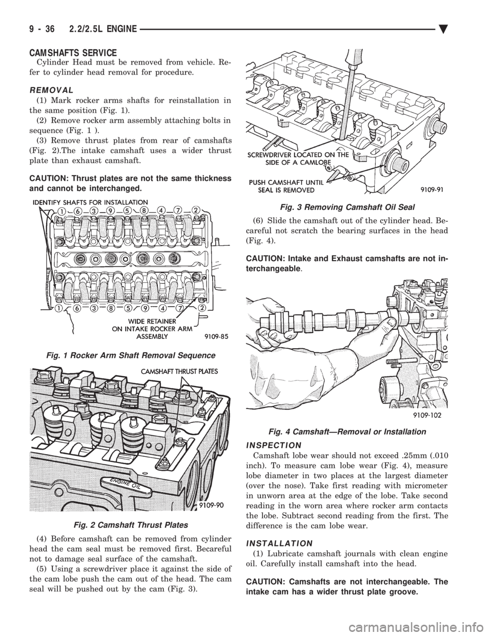
(1) Mark rocker arms shafts for reinstallation in
the same position (Fig. 1). (2) Remove rocker arm assembly attaching bolts in
sequence (Fig. 1 ). (3) Remove thrust plates from rear of camshafts
(Fig. 2).The intake camshaft uses a wider thrust
plate than exhaust camshaft.
CAUTION: Thrust plates are not the same thickness
and cannot be interchanged.
(4) Before camshaft can be removed from cylinder
head the cam seal must be removed first. Becareful
not to damage seal surface of the camshaft. (5) Using a screwdriver place it against the side of
the cam lobe push the cam out of the head. The cam
seal will be pushed out by the cam (Fig. 3). (6) Slide the camshaft out of the cylinder head. Be-
careful not scratch the bearing surfaces in the head
(Fig. 4).
CAUTION: Intake and Exhaust camshafts are not in-
terchangeable .
INSPECTION
Camshaft lobe wear should not exceed .25mm (.010
inch). To measure cam lobe wear (Fig. 4), measure
lobe diameter in two places at the largest diameter
(over the nose). Take first reading with micrometer
in unworn area at the edge of the lobe. Take second
reading in the worn area where rocker arm contacts
the lobe. Subtract second reading from the first. The
difference is the cam lobe wear.
INSTALLATION
(1) Lubricate camshaft journals with clean engine
oil. Carefully install camshaft into the head.
CAUTION: Camshafts are not interchangeable. The
intake cam has a wider thrust plate groove.
Fig. 3 Removing Camshaft Oil Seal
Fig. 1 Rocker Arm Shaft Removal Sequence
Fig. 2 Camshaft Thrust Plates
Fig. 4 CamshaftÐRemoval or Installation
9 - 36 2.2/2.5L ENGINE Ä
Page 1603 of 2438
(2) Install thrust plates and tighten retaining nuts
to6N Im (55 in. lbs.).
(3) Install new camshaft oil seals flush with cylin-
der head surface. Using seal installing special tool C-4680.
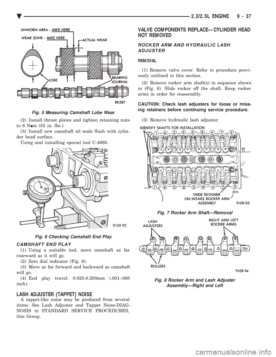
CAMSHAFT END PLAY
(1) Using a suitable tool, move camshaft as far
rearward as it will go. (2) Zero dial indicator (Fig. 6).
(3) Move as far forward and backward as camshaft
will go. (4) End play travel: 0.025-0.200mm (.001-.008
inch).
LASH ADJUSTER (TAPPET) NOISE
A tappet-like noise may be produced from several
items. See Lash Adjuster and Tappet Noise-DIAG-
NOSIS in STANDARD SERVICE PROCEDURES,
this Group.
VALVE COMPONENTS REPLACEÐCYLINDER HEAD
NOT REMOVED
ROCKER ARM AND HYDRAULIC LASH
ADJUSTER
REMOVAL
(1) Remove valve cover. Refer to procedure previ-
ously outlined in this section.
(2) Remove rocker arm shaft(s) in sequence shown
in (Fig. 6). Slide rocker off the shaft. Keep rocker
arms in order for reassembly.
CAUTION: Check lash adjusters for loose or miss-
ing retainers before continuing service procedure.
(3) Remove hydraulic lash adjuster.
Fig. 5 Measuring Camshaft Lobe Wear
Fig. 6 Checking Camshaft End Play
Fig. 7 Rocker Arm ShaftÐRemoval
Fig. 8 Rocker Arm and Lash Adjuster AssemblyÐRight and Left
Ä 2.2/2.5L ENGINE 9 - 37
Page 1604 of 2438
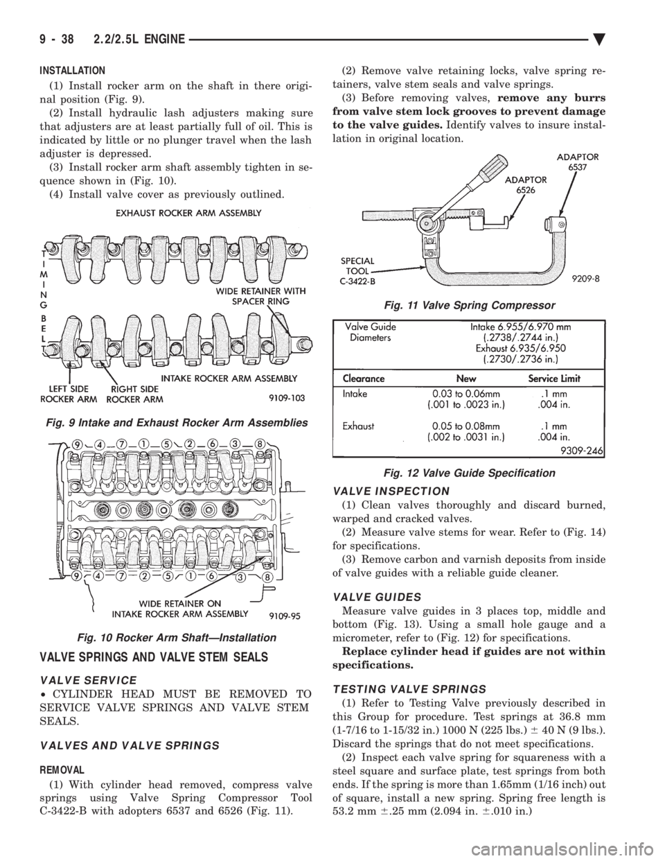
INSTALLATION (1) Install rocker arm on the shaft in there origi-
nal position (Fig. 9). (2) Install hydraulic lash adjusters making sure
that adjusters are at least partially full of oil. This is
indicated by little or no plunger travel when the lash
adjuster is depressed. (3) Install rocker arm shaft assembly tighten in se-
quence shown in (Fig. 10). (4) Install valve cover as previously outlined.
VALVE SPRINGS AND VALVE STEM SEALS
VALVE SERVICE
² CYLINDER HEAD MUST BE REMOVED TO
SERVICE VALVE SPRINGS AND VALVE STEM
SEALS.
VALVES AND VALVE SPRINGS
REMOVAL
(1) With cylinder head removed, compress valve
springs using Valve Spring Compressor Tool
C-3422-B with adopters 6537 and 6526 (Fig. 11). (2) Remove valve retaining locks, valve spring re-
tainers, valve stem seals and valve springs. (3) Before removing valves, remove any burrs
from valve stem lock grooves to prevent damage
to the valve guides. Identify valves to insure instal-
lation in original location.
VALVE INSPECTION
(1) Clean valves thoroughly and discard burned,
warped and cracked valves. (2) Measure valve stems for wear. Refer to (Fig. 14)
for specifications. (3) Remove carbon and varnish deposits from inside
of valve guides with a reliable guide cleaner.
VALVE GUIDES
Measure valve guides in 3 places top, middle and
bottom (Fig. 13). Using a small hole gauge and a
micrometer, refer to (Fig. 12) for specifications. Replace cylinder head if guides are not within
specifications.
TESTING VALVE SPRINGS
(1) Refer to Testing Valve previously described in
this Group for procedure. Test springs at 36.8 mm
(1-7/16 to 1-15/32 in.) 1000 N (225 lbs.) 640 N (9 lbs.).
Discard the springs that do not meet specifications. (2) Inspect each valve spring for squareness with a
steel square and surface plate, test springs from both
ends. If the spring is more than 1.65mm (1/16 inch) out
of square, install a new spring. Spring free length is
53.2 mm 6.25 mm (2.094 in. 6.010 in.)
Fig. 9 Intake and Exhaust Rocker Arm Assemblies
Fig. 10 Rocker Arm ShaftÐInstallation
Fig. 11 Valve Spring Compressor
Fig. 12 Valve Guide Specification
9 - 38 2.2/2.5L ENGINE Ä
Page 1605 of 2438
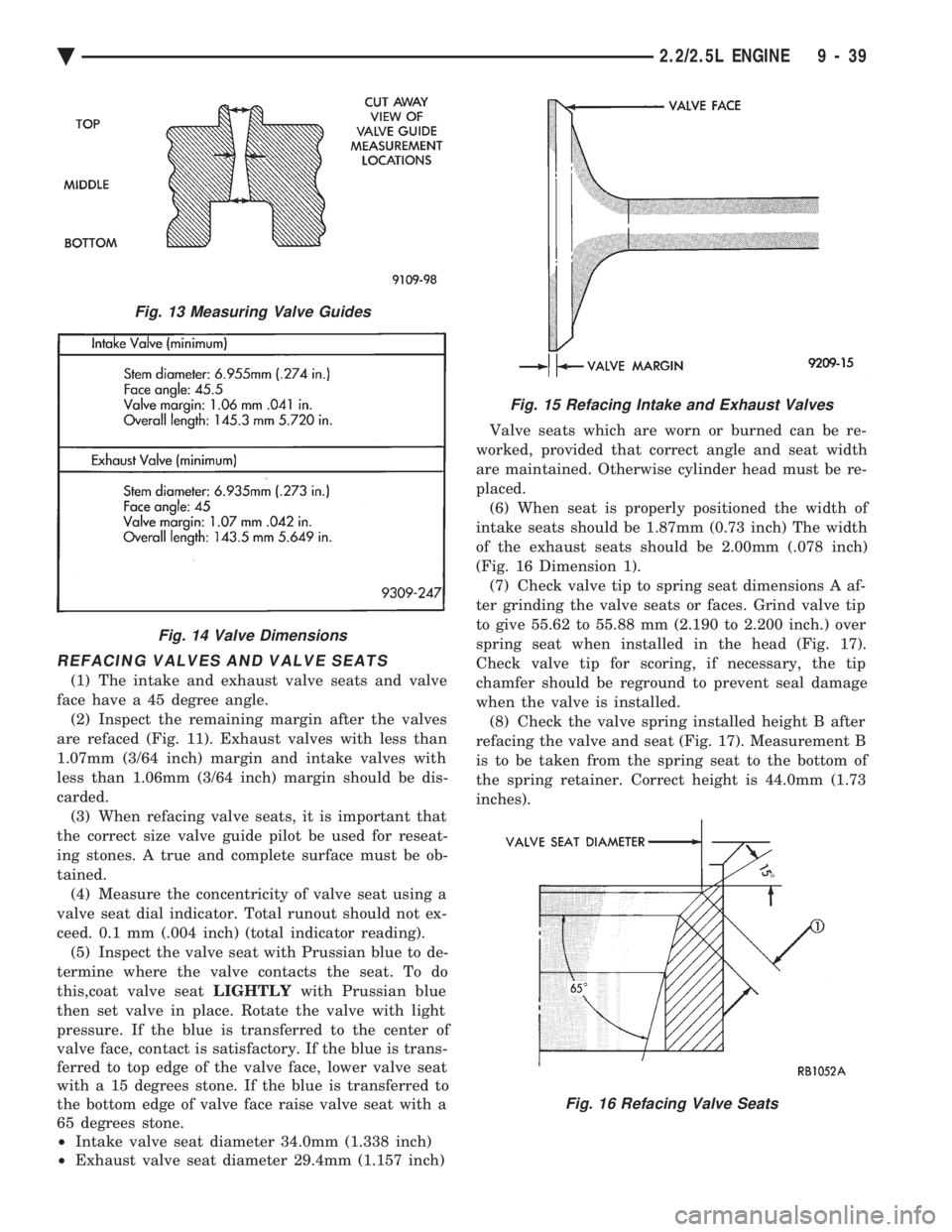
REFACING VALVES AND VALVE SEATS
(1) The intake and exhaust valve seats and valve
face have a 45 degree angle. (2) Inspect the remaining margin after the valves
are refaced (Fig. 11). Exhaust valves with less than
1.07mm (3/64 inch) margin and intake valves with
less than 1.06mm (3/64 inch) margin should be dis-
carded. (3) When refacing valve seats, it is important that
the correct size valve guide pilot be used for reseat-
ing stones. A true and complete surface must be ob-
tained. (4) Measure the concentricity of valve seat using a
valve seat dial indicator. Total runout should not ex-
ceed. 0.1 mm (.004 inch) (total indicator reading). (5) Inspect the valve seat with Prussian blue to de-
termine where the valve contacts the seat. To do
this,coat valve seat LIGHTLYwith Prussian blue
then set valve in place. Rotate the valve with light
pressure. If the blue is transferred to the center of
valve face, contact is satisfactory. If the blue is trans-
ferred to top edge of the valve face, lower valve seat
with a 15 degrees stone. If the blue is transferred to
the bottom edge of valve face raise valve seat with a
65 degrees stone.
² Intake valve seat diameter 34.0mm (1.338 inch)
² Exhaust valve seat diameter 29.4mm (1.157 inch) Valve seats which are worn or burned can be re-
worked, provided that correct angle and seat width
are maintained. Otherwise cylinder head must be re-
placed. (6) When seat is properly positioned the width of
intake seats should be 1.87mm (0.73 inch) The width
of the exhaust seats should be 2.00mm (.078 inch)
(Fig. 16 Dimension 1). (7) Check valve tip to spring seat dimensions A af-
ter grinding the valve seats or faces. Grind valve tip
to give 55.62 to 55.88 mm (2.190 to 2.200 inch.) over
spring seat when installed in the head (Fig. 17).
Check valve tip for scoring, if necessary, the tip
chamfer should be reground to prevent seal damage
when the valve is installed. (8) Check the valve spring installed height B after
refacing the valve and seat (Fig. 17). Measurement B
is to be taken from the spring seat to the bottom of
the spring retainer. Correct height is 44.0mm (1.73
inches).
Fig. 13 Measuring Valve Guides
Fig. 14 Valve Dimensions
Fig. 15 Refacing Intake and Exhaust Valves
Fig. 16 Refacing Valve Seats
Ä 2.2/2.5L ENGINE 9 - 39
Page 1606 of 2438
VALVE GEAR REASSEMBLY AFTER VALVE SERVICE
(1) Coat valve stems with lubrication oil and insert
in cylinder head. (2) Install new valve stem seals on all valves. The
valve stem seals should be pushed firmly and
squarely over valve guide. The lower edge of the seal
should be resting on the valve guide boss. (3) Install valve spring seats and springs and re-
tainers. Compress valve springs only enough to in-
stall locks, taking care not to misalign the direction
of compression. Nicked valve stems may result from
misalignment of the valve spring compressor.
CAUTION: When depressing the valve spring retain-
ers with Valve Spring Compressor Tool C-3422-B
with adopters 6537 and 6526 (Fig. 11) the locks can
become dislocated. Check to make sure both locks
are in their correct location after removing tool.
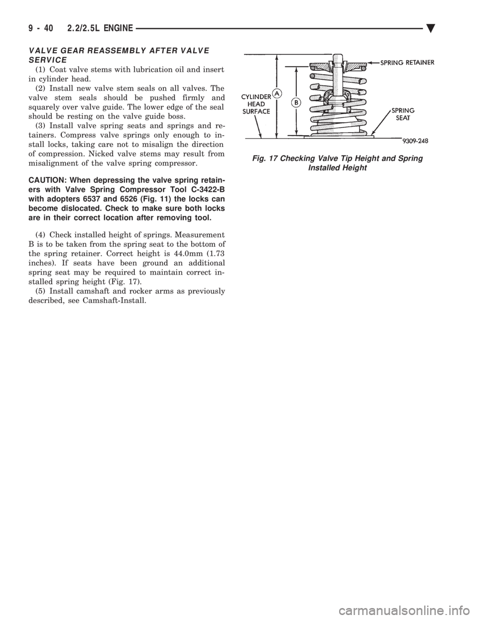
(4) Check installed height of springs. Measurement
B is to be taken from the spring seat to the bottom of
the spring retainer. Correct height is 44.0mm (1.73
inches). If seats have been ground an additional
spring seat may be required to maintain correct in-
stalled spring height (Fig. 17). (5) Install camshaft and rocker arms as previously
described, see Camshaft-Install.
Fig. 17 Checking Valve Tip Height and Spring Installed Height
9 - 40 2.2/2.5L ENGINE Ä
Page 1607 of 2438
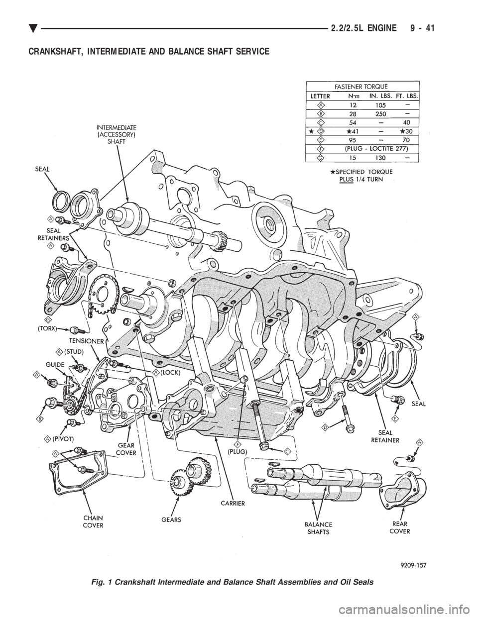
CRANKSHAFT, INTERMEDIATE AND BALANCE SHAFT SERVICE
Fig. 1 Crankshaft Intermediate and Balance Shaft Assemblies and Oil Seals
Ä 2.2/2.5L ENGINE 9 - 41
Page 1608 of 2438
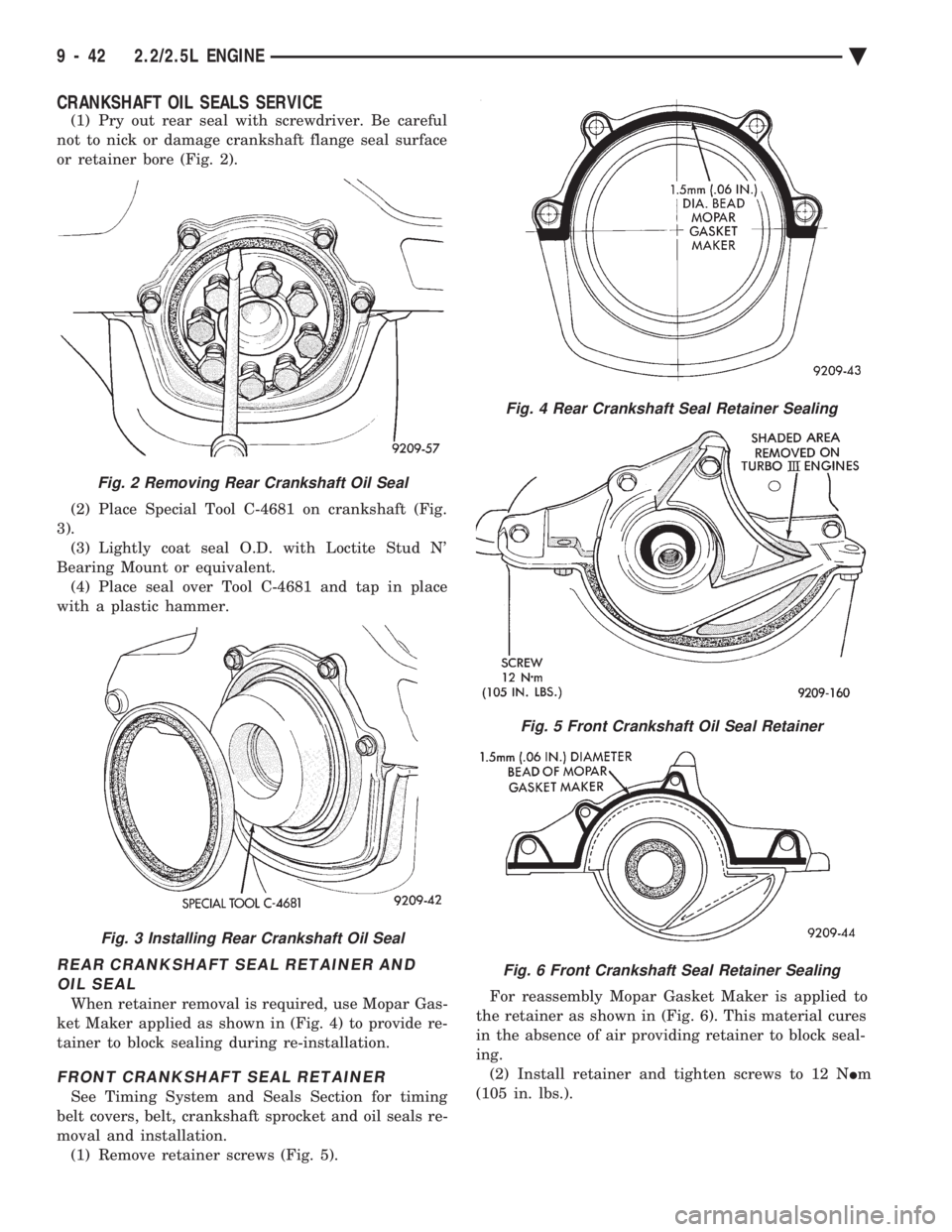
CRANKSHAFT OIL SEALS SERVICE
(1) Pry out rear seal with screwdriver. Be careful
not to nick or damage crankshaft flange seal surface
or retainer bore (Fig. 2).
(2) Place Special Tool C-4681 on crankshaft (Fig.
3). (3) Lightly coat seal O.D. with Loctite Stud N'
Bearing Mount or equivalent. (4) Place seal over Tool C-4681 and tap in place
with a plastic hammer.
REAR CRANKSHAFT SEAL RETAINER AND OIL SEAL
When retainer removal is required, use Mopar Gas-
ket Maker applied as shown in (Fig. 4) to provide re-
tainer to block sealing during re-installation.
FRONT CRANKSHAFT SEAL RETAINER
See Timing System and Seals Section for timing
belt covers, belt, crankshaft sprocket and oil seals re-
moval and installation. (1) Remove retainer screws (Fig. 5). For reassembly Mopar Gasket Maker is applied to
the retainer as shown in (Fig. 6). This material cures
in the absence of air providing retainer to block seal-
ing. (2) Install retainer and tighten screws to 12 N Im
(105 in. lbs.).
Fig. 2 Removing Rear Crankshaft Oil Seal
Fig. 3 Installing Rear Crankshaft Oil Seal
Fig. 4 Rear Crankshaft Seal Retainer Sealing
Fig. 5 Front Crankshaft Oil Seal Retainer
Fig. 6 Front Crankshaft Seal Retainer Sealing
9 - 42 2.2/2.5L ENGINE Ä
Page 1609 of 2438
CRANKSHAFT SERVICE
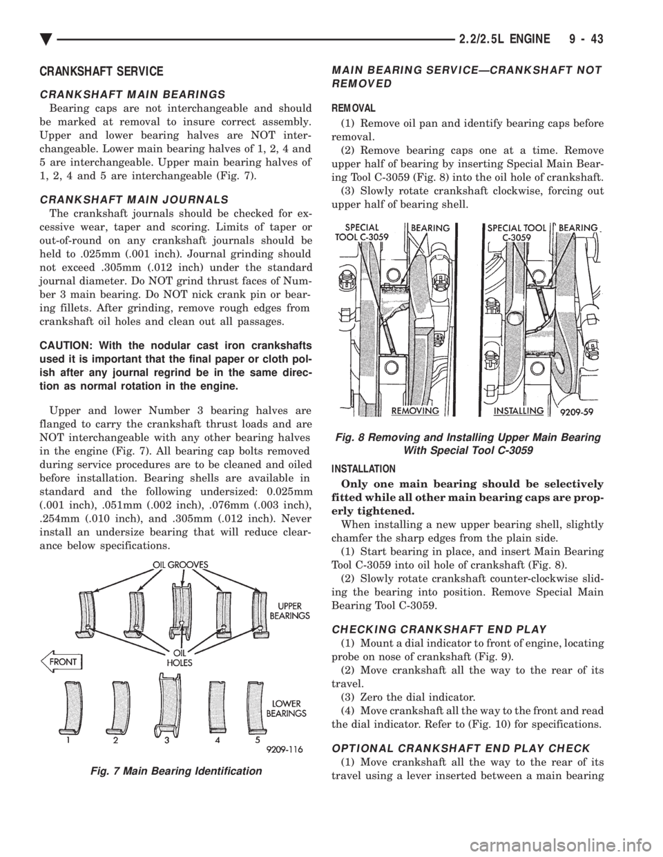
CRANKSHAFT MAIN BEARINGS
Bearing caps are not interchangeable and should
be marked at removal to insure correct assembly.
Upper and lower bearing halves are NOT inter-
changeable. Lower main bearing halves of 1, 2, 4 and
5 are interchangeable. Upper main bearing halves of
1, 2, 4 and 5 are interchangeable (Fig. 7).
CRANKSHAFT MAIN JOURNALS
The crankshaft journals should be checked for ex-
cessive wear, taper and scoring. Limits of taper or
out-of-round on any crankshaft journals should be
held to .025mm (.001 inch). Journal grinding should
not exceed .305mm (.012 inch) under the standard
journal diameter. Do NOT grind thrust faces of Num-
ber 3 main bearing. Do NOT nick crank pin or bear-
ing fillets. After grinding, remove rough edges from
crankshaft oil holes and clean out all passages.
CAUTION: With the nodular cast iron crankshafts
used it is important that the final paper or cloth pol-
ish after any journal regrind be in the same direc-
tion as normal rotation in the engine.
Upper and lower Number 3 bearing halves are
flanged to carry the crankshaft thrust loads and are
NOT interchangeable with any other bearing halves
in the engine (Fig. 7). All bearing cap bolts removed
during service procedures are to be cleaned and oiled
before installation. Bearing shells are available in
standard and the following undersized: 0.025mm
(.001 inch), .051mm (.002 inch), .076mm (.003 inch),
.254mm (.010 inch), and .305mm (.012 inch). Never
install an undersize bearing that will reduce clear-
ance below specifications.
MAIN BEARING SERVICEÐCRANKSHAFT NOT REMOVED
REMOVAL
(1) Remove oil pan and identify bearing caps before
removal. (2) Remove bearing caps one at a time. Remove
upper half of bearing by inserting Special Main Bear-
ing Tool C-3059 (Fig. 8) into the oil hole of crankshaft. (3) Slowly rotate crankshaft clockwise, forcing out
upper half of bearing shell.
INSTALLATION Only one main bearing should be selectively
fitted while all other main bearing caps are prop-
erly tightened. When installing a new upper bearing shell, slightly
chamfer the sharp edges from the plain side. (1) Start bearing in place, and insert Main Bearing
Tool C-3059 into oil hole of crankshaft (Fig. 8). (2) Slowly rotate crankshaft counter-clockwise slid-
ing the bearing into position. Remove Special Main
Bearing Tool C-3059.
CHECKING CRANKSHAFT END PLAY
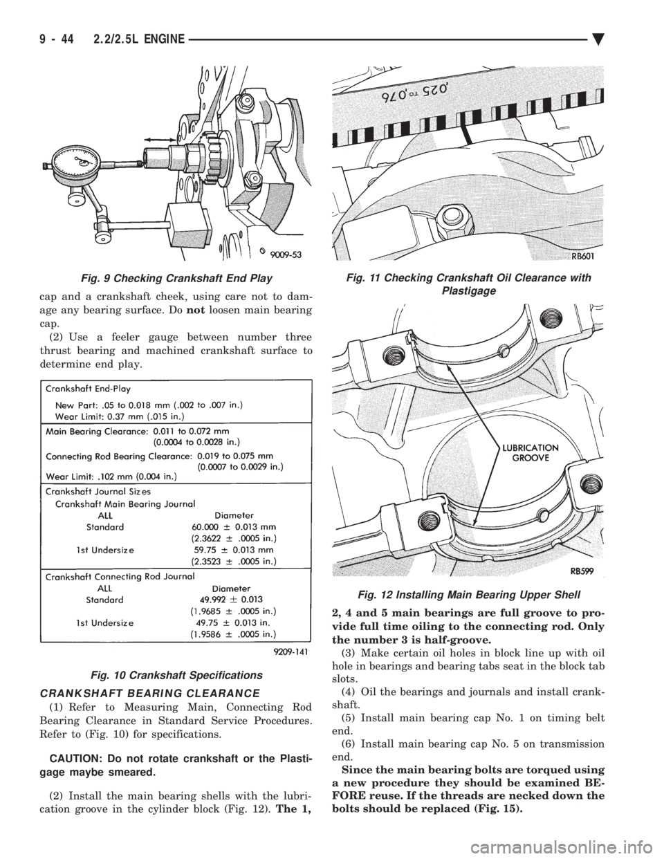
(1) Mount a dial indicator to front of engine, locating
probe on nose of crankshaft (Fig. 9). (2) Move crankshaft all the way to the rear of its
travel. (3) Zero the dial indicator.
(4) Move crankshaft all the way to the front and read
the dial indicator. Refer to (Fig. 10) for specifications.
OPTIONAL CRANKSHAFT END PLAY CHECK
(1) Move crankshaft all the way to the rear of its
travel using a lever inserted between a main bearingFig. 7 Main Bearing Identification
Fig. 8 Removing and Installing Upper Main Bearing With Special Tool C-3059
Ä 2.2/2.5L ENGINE 9 - 43
Page 1610 of 2438
cap and a crankshaft cheek, using care not to dam-
age any bearing surface. Do notloosen main bearing
cap. (2) Use a feeler gauge between number three
thrust bearing and machined crankshaft surface to
determine end play.
CRANKSHAFT BEARING CLEARANCE
(1) Refer to Measuring Main, Connecting Rod
Bearing Clearance in Standard Service Procedures.
Refer to (Fig. 10) for specifications.
CAUTION: Do not rotate crankshaft or the Plasti-
gage maybe smeared.
(2) Install the main bearing shells with the lubri-
cation groove in the cylinder block (Fig. 12). The 1, 2, 4 and 5 main bearings are full groove to pro-
vide full time oiling to the connecting rod. Only
the number 3 is half-groove.
(3) Make certain oil holes in block line up with oil
hole in bearings and bearing tabs seat in the block tab
slots. (4) Oil the bearings and journals and install crank-
shaft. (5) Install main bearing cap No. 1 on timing belt
end. (6) Install main bearing cap No. 5 on transmission
end. Since the main bearing bolts are torqued using
a new procedure they should be examined BE-
FORE reuse. If the threads are necked down the
bolts should be replaced (Fig. 15).
Fig. 9 Checking Crankshaft End Play
Fig. 10 Crankshaft Specifications
Fig. 11 Checking Crankshaft Oil Clearance with Plastigage
Fig. 12 Installing Main Bearing Upper Shell
9 - 44 2.2/2.5L ENGINE Ä