lock CHEVROLET PLYMOUTH ACCLAIM 1993 Service Manual
[x] Cancel search | Manufacturer: CHEVROLET, Model Year: 1993, Model line: PLYMOUTH ACCLAIM, Model: CHEVROLET PLYMOUTH ACCLAIM 1993Pages: 2438, PDF Size: 74.98 MB
Page 737 of 2438
POWER MIRRORS
CONTENTS
page page
AUTOMATIC DAY/NIGHT INSIDE MIRROR .... 7
AUTOMATIC DAY/NIGHT INSIDE MIRROR WITH ULTRALIGHT HEADLAMP CONTROL ....... 7
GENERAL INFORMATION .................. 1
HEATED MIRROR ........................ 2
INSIDE MIRROR/READING LAMPS BULB/LENS REPLACEMENT ........................ 6
INSIDE MIRROR/READING LAMPS REPLACEMENT ........................ 6
MIRROR ASSEMBLY REPLACEMENTÐAA BODY.5
MIRROR ASSEMBLY REPLACEMENTÐ AC AND AY BODIES .................... 5
MIRROR ASSEMBLY REPLACEMENTÐAG BODY.5
MIRROR ASSEMBLY REPLACEMENTÐAJ BODY.5
MIRROR ASSEMBLY REPLACEMENTÐAP BODY.5
MIRROR MOTOR TEST PROCEDURE ........ 2
MIRROR SWITCH REPLACEMENTÐAA BODY . 3
MIRROR SWITCH REPLACEMENTÐAC AND AY BODIES .............................. 4
MIRROR SWITCH REPLACEMENTÐAG AND AJ BODIES .............................. 3
MIRROR SWITCH REPLACEMENTÐAP BODY . 4
MIRROR SWITCH TEST PROCEDURE ....... 2
TEST PROCEDURES ...................... 2
GENERAL INFORMATION
Electrically operated power mirrors are available
on all car lines. The mirrors are controlled by a sin-
gle switch assembly located either on the driver's
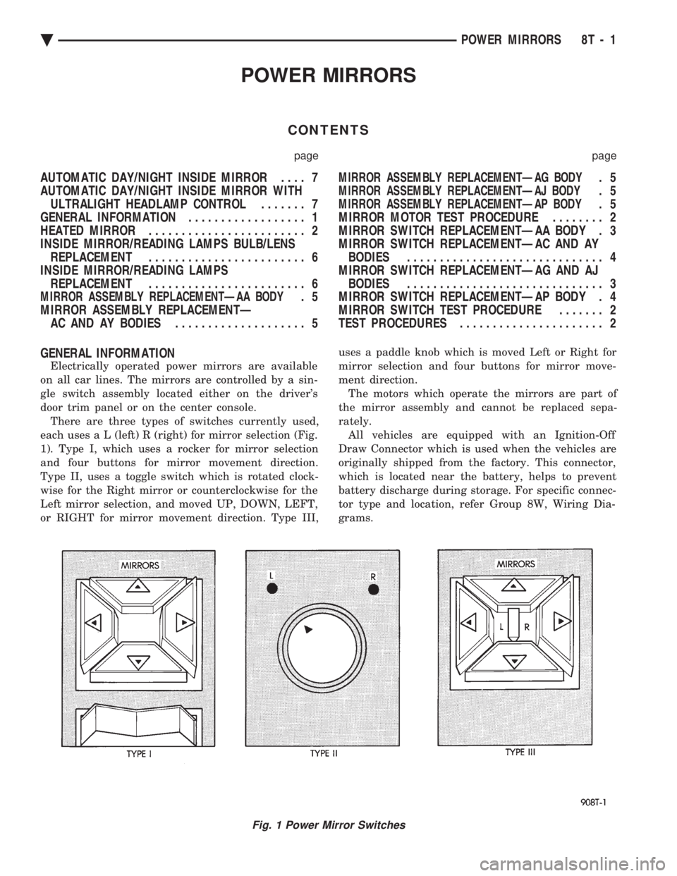
door trim panel or on the center console. There are three types of switches currently used,
each use s a L (left) R (right) for mirror selection (Fig.
1). Type I, which uses a rocker for mirror selection
and four buttons for mirror movement direction.
Type II, uses a toggle switch which is rotated clock-
wise for the Right mirror or counterclockwise for the
Left mirror selection, and moved UP, DOWN, LEFT,
or RIGHT for mirror movement direction. Type III, uses a paddle knob which is moved Left or Right for
mirror selection and four buttons for mirror move-
ment direction.
The motors which operate the mirrors are part of
the mirror assembly and cannot be replaced sepa-
rately. All vehicles are equipped with an Ignition-Off
Draw Connector which is used when the vehicles are
originally shipped from the factory. This connector,
which is located near the battery, helps to prevent
battery discharge during storage. For specific connec-
tor type and location, refer Group 8W, Wiring Dia-
grams.
Fig. 1 Power Mirror Switches
Ä POWER MIRRORS 8T - 1
Page 742 of 2438
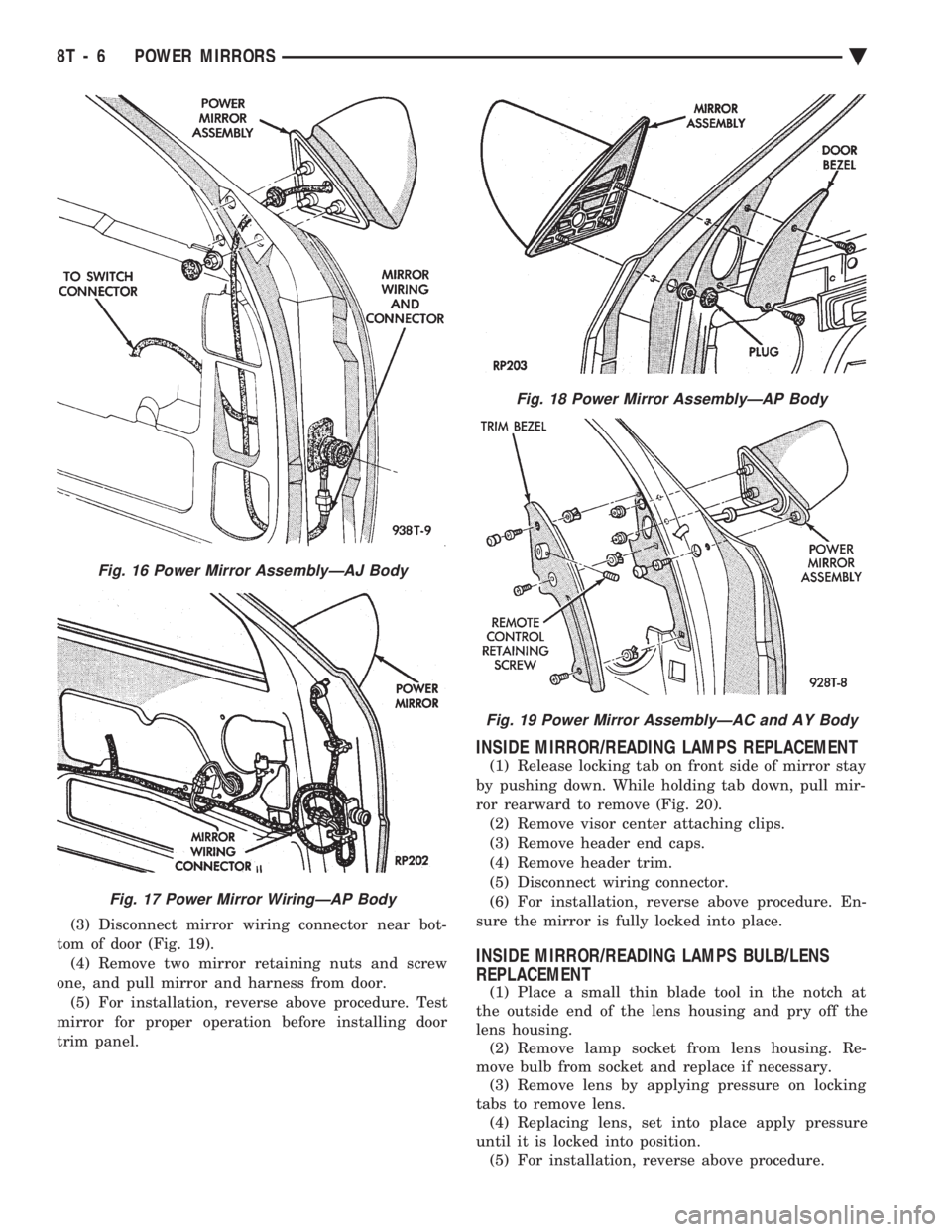
(3) Disconnect mirror wiring connector near bot-
tom of door (Fig. 19). (4) Remove two mirror retaining nuts and screw
one, and pull mirror and harness from door. (5) For installation, reverse above procedure. Test
mirror for proper operation before installing door
trim panel.
INSIDE MIRROR/READING LAMPS REPLACEMENT
(1) Release locking tab on front side of mirror stay
by pushing down. While holding tab down, pull mir-
ror rearward to remove (Fig. 20). (2) Remove visor center attaching clips.
(3) Remove header end caps.
(4) Remove header trim.
(5) Disconnect wiring connector.
(6) For installation, reverse above procedure. En-
sure the mirror is fully locked into place.
INSIDE MIRROR/READING LAMPS BULB/LENS
REPLACEMENT
(1) Place a small thin blade tool in the notch at
the outside end of the lens housing and pry off the
lens housing. (2) Remove lamp socket from lens housing. Re-
move bulb from socket and replace if necessary. (3) Remove lens by applying pressure on locking
tabs to remove lens. (4) Replacing lens, set into place apply pressure
until it is locked into position. (5) For installation, reverse above procedure.
Fig. 16 Power Mirror AssemblyÐAJ Body
Fig. 17 Power Mirror WiringÐAP Body
Fig. 18 Power Mirror AssemblyÐAP Body
Fig. 19 Power Mirror AssemblyÐAC and AY Body
8T - 6 POWER MIRRORS Ä
Page 755 of 2438
When a fusible link blows it is important to find
out what the problem is. They are placed in the sys-
tem for protection against shorts. Which can be
caused by a component failure or wiring failures. Do
not just replace the fusible link to correct the
problem. When diagnosing a faulty fusible link it is impor-
tant to check the wire carefully. In some instances
the link may be blown and it will not show through
the insulation, the wire should be checked over its
entire length for internal breaks. (1) Disconnect battery negative cable.
(2) Cut out the blown portion of the fusible link.
(3) Strip 1 inch of insulation from each end of the
existing fusible link. (4) Place a piece of heat shrink tubing over one
side of the fusible link. Make sure the tubing will be
long enough to cover and seal the entire repair area. (5) Cut a replacement piece of fusible link approx-
imately two inches longer than the piece removed. (6) Remove one inch of insulation from each end of
the replacement fusible link. (7) Spread the strands of wire apart on each of the
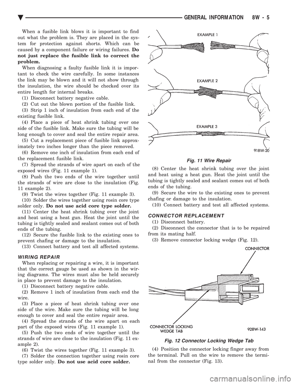
exposed wires (Fig. 11 example 1). (8) Push the two ends of the wire together until
the strands of wire are close to the insulation (Fig.
11 example 2). (9) Twist the wires together (Fig. 11 example 3).
(10) Solder the wires together using rosin core type
solder only. Do not use acid core type solder.
(11) Center the heat shrink tubing over the joint
and heat using a heat gun. Heat the joint until the
tubing is tightly sealed and sealant comes out of both
ends of the tubing. (12) Secure the fusible link to the existing ones to
prevent chafing or damage to the insulation. (13) Connect battery and test all affected systems.
WIRING REPAIR
When replacing or repairing a wire, it is important
that the correct gauge be used as shown in the wir-
ing diagrams. The wires must also be held securely
in place to prevent damage to the insulation. (1) Disconnect battery negative cable.
(2) Remove 1 inch of insulation from each end the
wire. (3) Place a piece of heat shrink tubing over one
side of the wire. Make sure the tubing will be long
enough to cover and seal the entire repair area. (4) Spread the strands of the wire apart on each
part of the exposed wires (Fig. 11 example 1). (5) Push the two ends of wire together until the
strands of wire are close to the insulation (Fig. 11 ex-
ample 2). (6) Twist the wires together (Fig. 11 example 3).
(7) Solder the connection together using rosin core
type solder only. Do not use acid core solder. (8) Center the heat shrink tubing over the joint
and heat using a heat gun. Heat the joint until the
tubing is tightly sealed and sealant comes out of both
ends of the tubing. (9) Secure the wire to the existing ones to prevent
chafing or damage to the insulation. (10) Connect battery and test all affected systems.
CONNECTOR REPLACEMENT
(1) Disconnect battery.
(2) Disconnect the connector that is to be repaired
from its mating half. (3) Remove connector locking wedge (Fig. 12).
(4) Position the connector locking finger away from
the terminal. Pull on the wire to remove the termi-
nal from the connector (Fig. 13).
Fig. 11 Wire Repair
Fig. 12 Connector Locking Wedge Tab
Ä GENERAL INFORMATION 8W - 5
Page 756 of 2438
(5) Reset the terminal locking tang, if it has one.
(6) Insert the removed wire in the same cavity on
the repair connector. (7) Repeat steps four thru six for each wire in the
connector. Check that all wires are inserted into the
proper cavities. For connector pin out identification
refer to the wiring diagrams. (8) Insert the connector locking wedge into the re-
paired connector. (9) Connect connector to its mating half.
(10) Connect battery and test all affected systems.
CONNECTOR AND TERMINAL ASSEMBLY REPLACEMENT
(1) Disconnect Battery.
(2) Disconnect the connector being repaired form
its mating half. (3) Cut off the existing wire connector directly be-
hind the insulator. Remove six inches of tape from
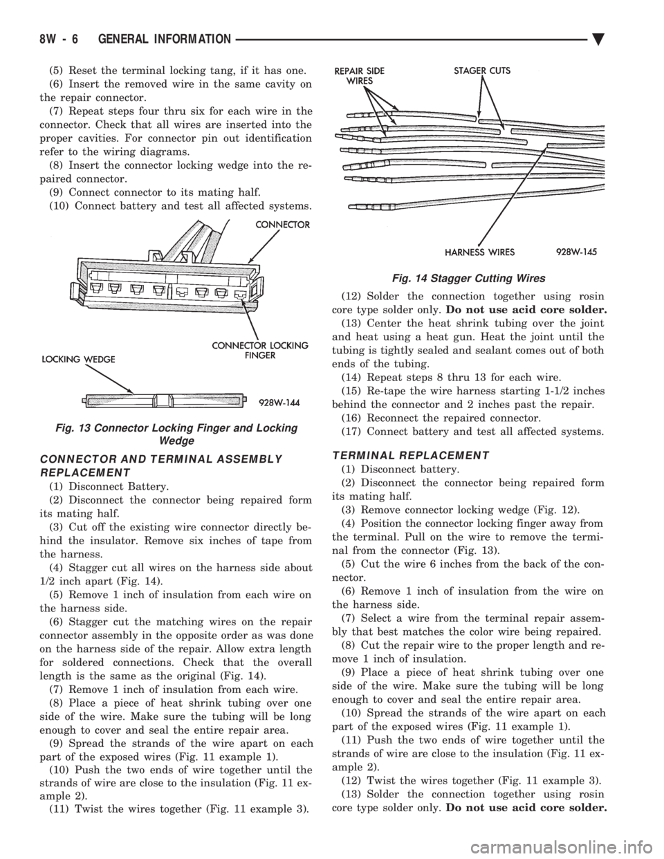
the harness. (4) Stagger cut all wires on the harness side about
1/2 inch apart (Fig. 14). (5) Remove 1 inch of insulation from each wire on
the harness side. (6) Stagger cut the matching wires on the repair
connector assembly in the opposite order as was done
on the harness side of the repair. Allow extra length
for soldered connections. Check that the overall
length is the same as the original (Fig. 14). (7) Remove 1 inch of insulation from each wire.
(8) Place a piece of heat shrink tubing over one
side of the wire. Make sure the tubing will be long
enough to cover and seal the entire repair area. (9) Spread the strands of the wire apart on each
part of the exposed wires (Fig. 11 example 1). (10) Push the two ends of wire together until the
strands of wire are close to the insulation (Fig. 11 ex-
ample 2). (11) Twist the wires together (Fig. 11 example 3). (12) Solder the connection together using rosin
core type solder only. Do not use acid core solder.
(13) Center the heat shrink tubing over the joint
and heat using a heat gun. Heat the joint until the
tubing is tightly sealed and sealant comes out of both
ends of the tubing. (14) Repeat steps 8 thru 13 for each wire.
(15) Re-tape the wire harness starting 1-1/2 inches
behind the connector and 2 inches past the repair. (16) Reconnect the repaired connector.
(17) Connect battery and test all affected systems.
TERMINAL REPLACEMENT
(1) Disconnect battery.
(2) Disconnect the connector being repaired form
its mating half. (3) Remove connector locking wedge (Fig. 12).
(4) Position the connector locking finger away from
the terminal. Pull on the wire to remove the termi-
nal from the connector (Fig. 13). (5) Cut the wire 6 inches from the back of the con-
nector. (6) Remove 1 inch of insulation from the wire on
the harness side. (7) Select a wire from the terminal repair assem-
bly that best matches the color wire being repaired. (8) Cut the repair wire to the proper length and re-
move 1 inch of insulation. (9) Place a piece of heat shrink tubing over one
side of the wire. Make sure the tubing will be long
enough to cover and seal the entire repair area. (10) Spread the strands of the wire apart on each
part of the exposed wires (Fig. 11 example 1). (11) Push the two ends of wire together until the
strands of wire are close to the insulation (Fig. 11 ex-
ample 2). (12) Twist the wires together (Fig. 11 example 3).
(13) Solder the connection together using rosin
core type solder only. Do not use acid core solder.
Fig. 13 Connector Locking Finger and Locking
Wedge
Fig. 14 Stagger Cutting Wires
8W - 6 GENERAL INFORMATION Ä
Page 757 of 2438
(14) Center the heat shrink tubing over the joint
and heat using a heat gun. Heat the joint until the
tubing is tightly sealed and sealant comes out of both
ends of the tubing. (15) Insert the repaired wire into the connector.
(16) Install the connector locking wedge and recon-
nect the connector to its mating half. (17) Re-tape the wire harness starting 1-1/2 inches
behind the connector and 2 inches past the repair. (18) Connect battery and test all affected systems.
SYMBOLS, FUSES AND RELAYS
Various symbols are used throughout the wiring
diagrams. These symbols can be identified by refer-
ring to the symbol identification chart (Fig. 15). For fuse block, relay bank, or power distribution
center information refer to the fuse charts and relay
bank section.
CAUTION: When replacing a blown fuse it is impor-
tant to replace it with a fuse having the correct am-
perage rating. The use of a fuse with a rating other
than indicated may result in an electrical overload.
If a proper rated fuse continues to blow, it indicates
a problem that should be corrected.
Ä GENERAL INFORMATION 8W - 7
Page 759 of 2438
FUSE CHARTS AND RELAY BANKS
INDEX
Caption Fig.
Fuse Block and Relay Bank AA Body .................1
Fuse Block AC, AY Body .........................2
Fuse Block AG, AJ Body .........................3
Fuse Block and Relay Bank AP Body .................4Caption Fig.
Power Distribution Center AC, AY Body ................7
Power Distribution Center AG, AJ Body ................8
Relay Bank AC, AY Body .........................5
Relay Bank AG, AJ Body .........................6
Ä FUSE CHARTS AND RELAY BANKS 8W - 9
Page 760 of 2438
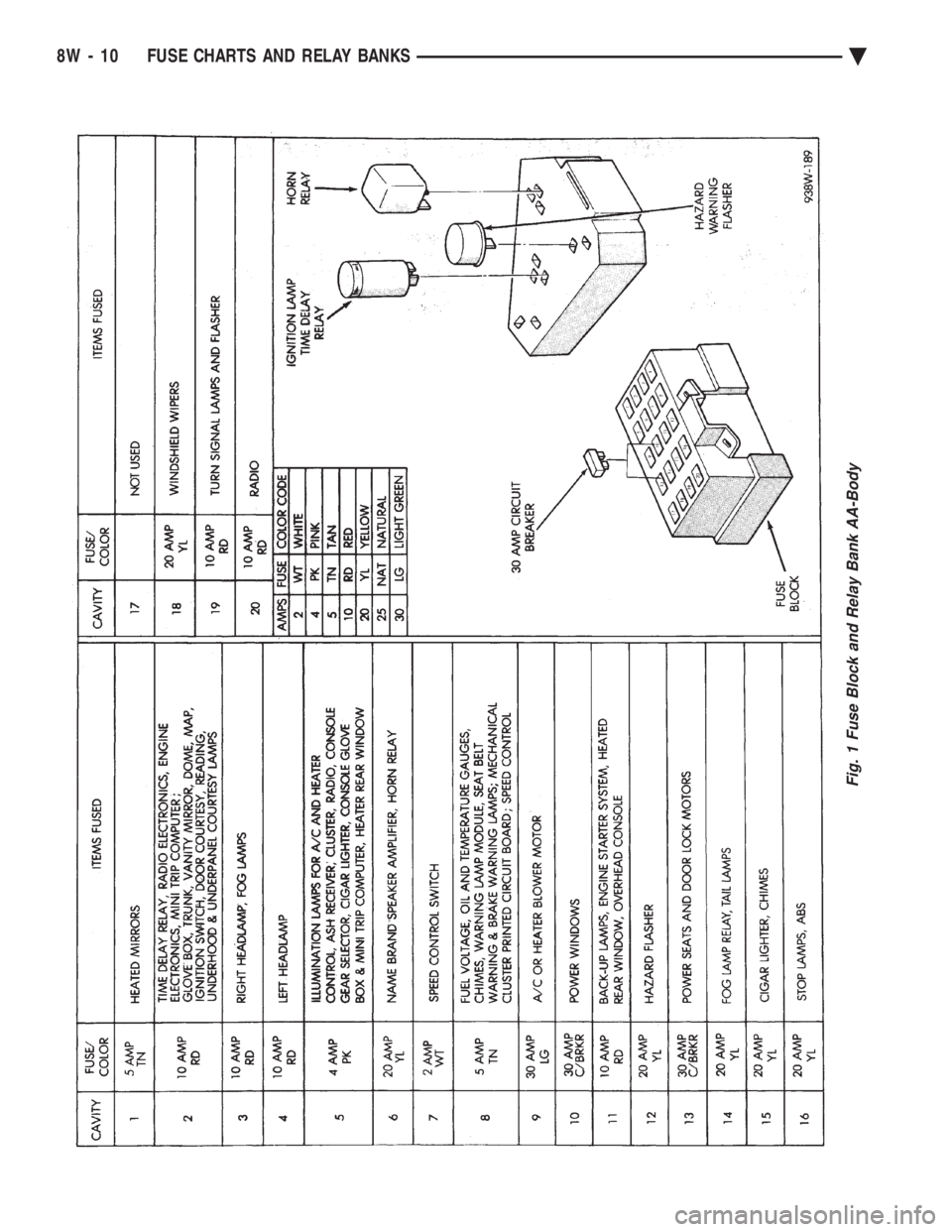
Fig. 1 Fuse Block and Relay Bank AA-Body
8W - 10 FUSE CHARTS AND RELAY BANKS Ä
Page 761 of 2438
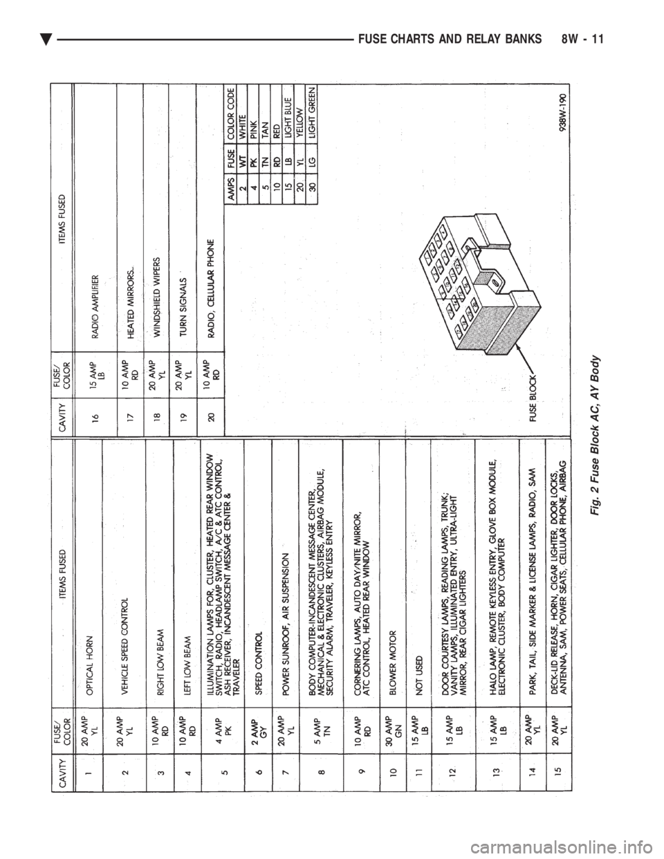
Fig. 2 Fuse Block AC, AY Body
Ä FUSE CHARTS AND RELAY BANKS 8W - 11
Page 762 of 2438
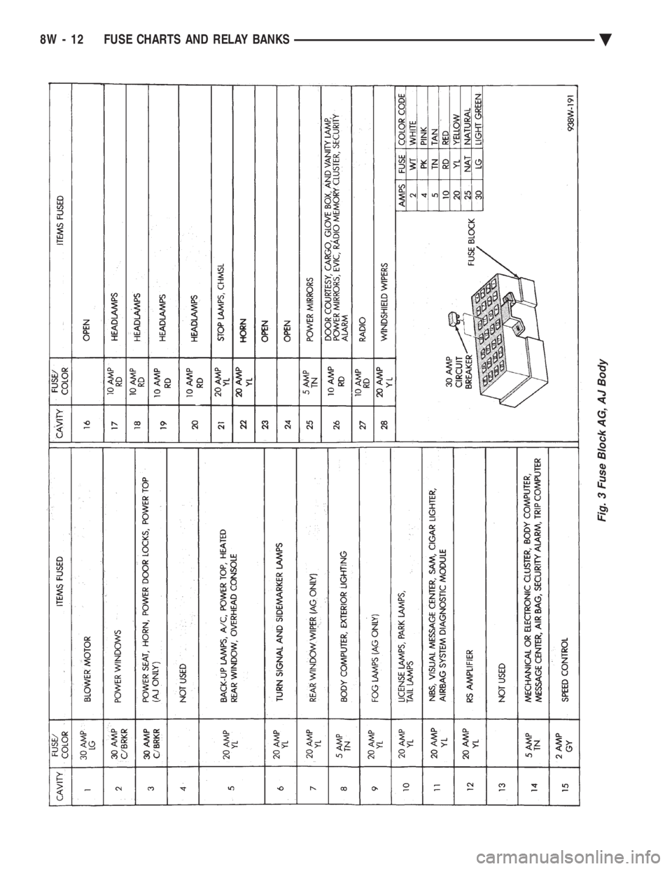
Fig. 3 Fuse Block AG, AJ Body
8W - 12 FUSE CHARTS AND RELAY BANKS Ä
Page 763 of 2438
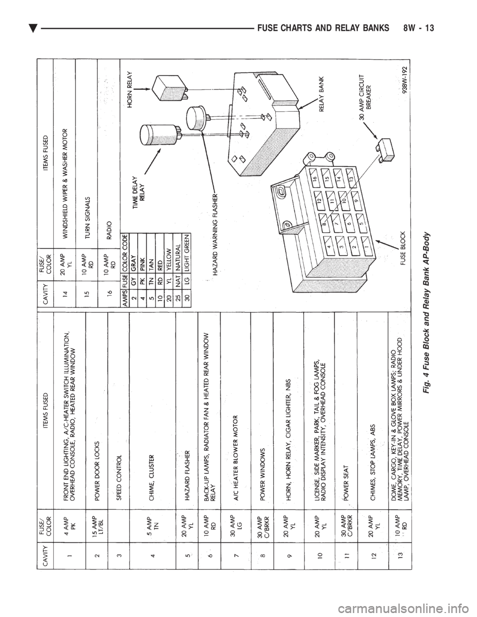
Fig. 4 Fuse Block and Relay Bank AP-Body
Ä FUSE CHARTS AND RELAY BANKS 8W - 13