battery capacity CHEVROLET PLYMOUTH ACCLAIM 1993 Service Manual
[x] Cancel search | Manufacturer: CHEVROLET, Model Year: 1993, Model line: PLYMOUTH ACCLAIM, Model: CHEVROLET PLYMOUTH ACCLAIM 1993Pages: 2438, PDF Size: 74.98 MB
Page 40 of 2438

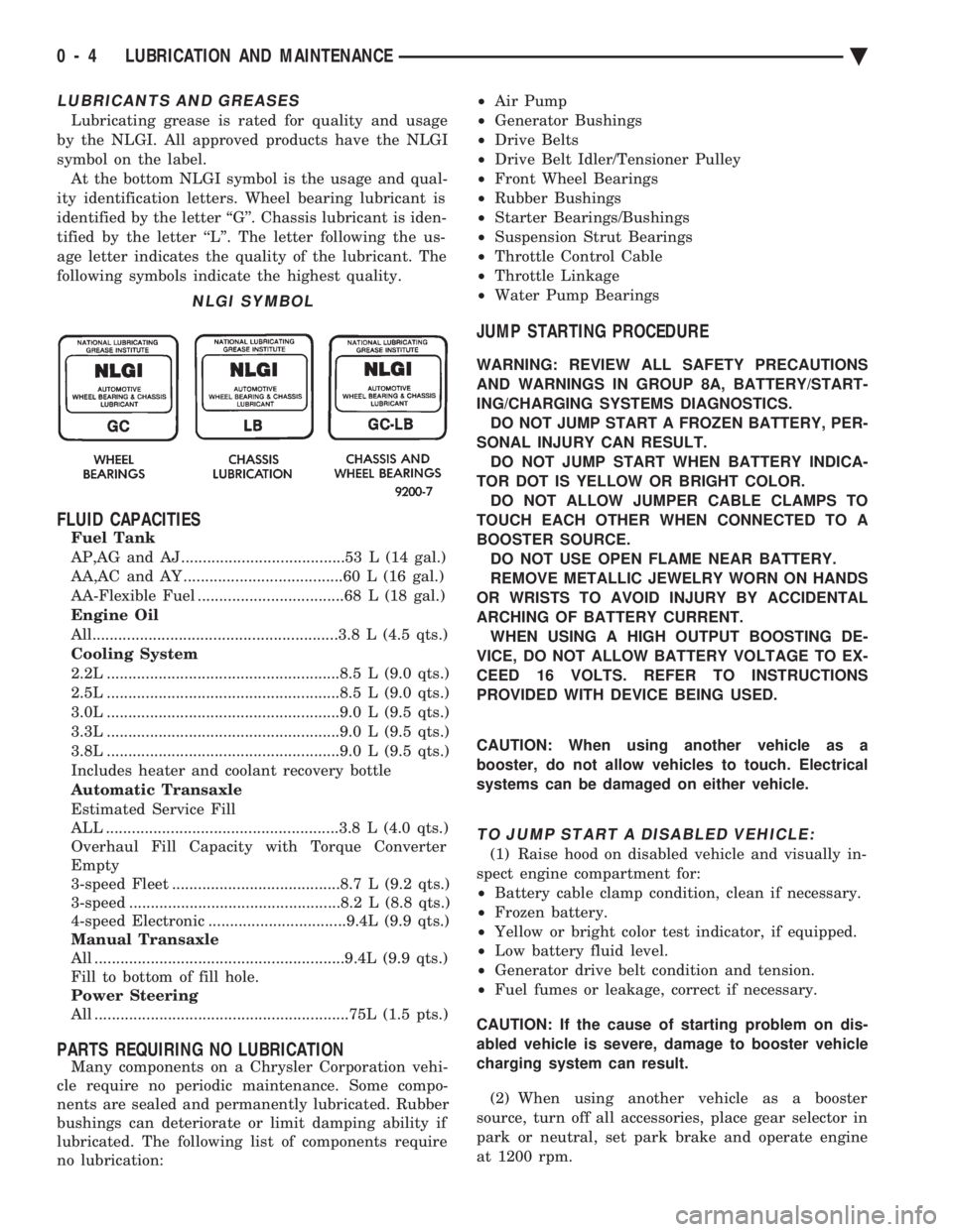
LUBRICANTS AND GREASES
Lubricating grease is rated for quality and usage
by the NLGI. All approved products have the NLGI
symbol on the label. At the bottom NLGI symbol is the usage and qual-
ity identification letters. Wheel bearing lubricant is
identified by the letter ``G''. Chassis lubricant is iden-
tified by the letter ``L''. The letter following the us-
age letter indicates the quality of the lubricant. The
following symbols indicate the highest quality.
FLUID CAPACITIES
Fuel Tank
AP,AG and AJ ......................................53 L (14 gal.)
AA,AC and AY .....................................60 L (16 gal.)
AA-Flexible Fuel ..................................68 L (18 gal.)
Engine Oil
All.........................................................3.8 L (4.5 qts.)
Cooling System
2.2L ......................................................8.5 L (9.0 qts.)
2.5L ......................................................8.5 L (9.0 qts.)
3.0L ......................................................9.0 L (9.5 qts.)
3.3L ......................................................9.0 L (9.5 qts.)
3.8L ......................................................9.0 L (9.5 qts.)
Includes heater and coolant recovery bottle
Automatic Transaxle
Estimated Service Fill
ALL ......................................................3.8 L (4.0 qts.)
Overhaul Fill Capacity with Torque Converter
Empty
3-speed Fleet .......................................8.7 L (9.2 qts.)
3-speed .................................................8.2 L (8.8 qts.)
4-speed Electronic ................................9.4L (9.9 qts.)
Manual Transaxle
All ..........................................................9.4L (9.9 qts.)
Fill to bottom of fill hole.
Power Steering
All ...........................................................75L (1.5 pts.)
PARTS REQUIRING NO LUBRICATION
Many components on a Chrysler Corporation vehi-
cle require no periodic maintenance. Some compo-
nents are sealed and permanently lubricated. Rubber
bushings can deteriorate or limit damping ability if
lubricated. The following list of components require
no lubrication: ²
Air Pump
² Generator Bushings
² Drive Belts
² Drive Belt Idler/Tensioner Pulley
² Front Wheel Bearings
² Rubber Bushings
² Starter Bearings/Bushings
² Suspension Strut Bearings
² Throttle Control Cable
² Throttle Linkage
² Water Pump Bearings
JUMP STARTING PROCEDURE
WARNING: REVIEW ALL SAFETY PRECAUTIONS
AND WARNINGS IN GROUP 8A, BATTERY/START-
ING/CHARGING SYSTEMS DIAGNOSTICS. DO NOT JUMP START A FROZEN BATTERY, PER-
SONAL INJURY CAN RESULT. DO NOT JUMP START WHEN BATTERY INDICA-
TOR DOT IS YELLOW OR BRIGHT COLOR. DO NOT ALLOW JUMPER CABLE CLAMPS TO
TOUCH EACH OTHER WHEN CONNECTED TO A
BOOSTER SOURCE. DO NOT USE OPEN FLAME NEAR BATTERY.
REMOVE METALLIC JEWELRY WORN ON HANDS
OR WRISTS TO AVOID INJURY BY ACCIDENTAL
ARCHING OF BATTERY CURRENT. WHEN USING A HIGH OUTPUT BOOSTING DE-
VICE, DO NOT ALLOW BATTERY VOLTAGE TO EX-
CEED 16 VOLTS. REFER TO INSTRUCTIONS
PROVIDED WITH DEVICE BEING USED.
CAUTION: When using another vehicle as a
booster, do not allow vehicles to touch. Electrical
systems can be damaged on either vehicle.
TO JUMP START A DISABLED VEHICLE:
(1) Raise hood on disabled vehicle and visually in-
spect engine compartment for:
² Battery cable clamp condition, clean if necessary.
² Frozen battery.
² Yellow or bright color test indicator, if equipped.
² Low battery fluid level.
² Generator drive belt condition and tension.
² Fuel fumes or leakage, correct if necessary.
CAUTION: If the cause of starting problem on dis-
abled vehicle is severe, damage to booster vehicle
charging system can result.
(2) When using another vehicle as a booster
source, turn off all accessories, place gear selector in
park or neutral, set park brake and operate engine
at 1200 rpm.
NLGI SYMBOL
0 - 4 LUBRICATION AND MAINTENANCE Ä
Page 376 of 2438

It is important when using the Test Indicator that
the battery be level and have a clean top to see the
correct indications. A light may be required to view
the Indicator.
WARNING: DO NOT USE OPEN FLAME NEAR BAT-
TERY BECAUSE OF EXPLOSIVE GASES AT FORM
ABOVE BATTERY.
STATE OF CHARGE TESTS
USING TEST INDICATOR
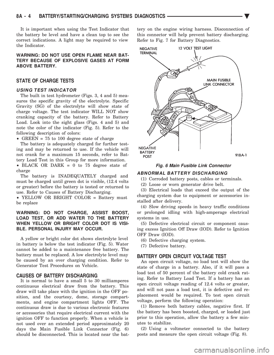
The built in test hydrometer (Figs. 3, 4 and 5) mea-
sures the specific gravity of the electrolyte. Specific
Gravity (SG) of the electrolyte will show state of
charge voltage. The test indicator WILL NOT show
cranking capacity of the battery. Refer to Battery
Load. Look into the sight glass (Figs. 4 and 5) and
note the color of the indicator (Fig. 5). Refer to the
following description of colors:
² GREEN = 75 to 100 degree state of charge
The battery is adequately charged for further test-
ing and may be returned to use. If the vehicle will
not crank for a maximum 15 seconds, refer to Bat-
tery Load Test in this Group for more information.
² BLACK OR DAR K=0to75degree state of
charge The battery is INADEQUATELY charged and
must be charged until green dot is visible, (12.4 volts
or greater) before the battery is tested or returned to
use. Refer to Causes of Battery Discharging.
² YELLOW OR BRIGHT COLOR = Battery must
be replace
WARNING: DO NOT CHARGE, ASSIST BOOST,
LOAD TEST, OR ADD WATER TO THE BATTERY
WHEN YELLOW OR BRIGHT COLOR DOT IS VISI-
BLE. PERSONAL INJURY MAY OCCUR.
A yellow or bright color dot shows electrolyte level
in battery is below the test indicator (Fig. 5). Water
cannot be added to a maintenance free battery. The
battery must be replaced. A low electrolyte level may
be caused by an over charging condition. Refer to
Generator Test Procedures on Vehicle.
CAUSES OF BATTERY DISCHARGING
It is normal to have a small 5 to 30 milliamperes
continuous electrical draw from the battery. This
draw will take place with the ignition in the OFF po-
sition, and the courtesy, dome, storage compart-
ments, and engine compartment lights OFF. The
continuous draw is due to various electronic features
or accessories that require electrical current with the
ignition OFF to function properly. When a vehicle is
not used over an extended period approximately 20
days the Main Fusible Link Connector (Fig. 6)
should be disconnected. This is located near the bat- tery on the engine wiring harness. Disconnection of
this connector will help prevent battery discharging.
Refer to Fig. 7 for Battery Diagnostics.
ABNORMAL BATTERY DISCHARGING
(1) Corroded battery posts, cables or terminals.
(2) Loose or worn generator drive belt.
(3) Electrical loads that exceed the output of the
charging system due to equipment or accessories in-
stalled after delivery. (4) Slow driving speeds in heavy traffic conditions
or prolonged idling with high-amperage electrical
systems in use. (5) Defective electrical circuit or component caus-
ing excess Ignition Off Draw (IOD). Refer to Ignition
OFF Draw (IOD). (6) Defective charging system.
(7) Defective battery.
BATTERY OPEN CIRCUIT VOLTAGE TEST
An open circuit voltage, no load test will show the
state of charge in a battery. Also, if it will pass a
load test of 50 percent of the battery cold crank rat-
ing. Refer to Battery Load Test. If a battery has an
open circuit voltage reading of 12.4 volts or greater,
and will not pass a load test, it is defective and re-
placement would be required. To test open circuit
voltage, perform the following operation: (1) Remove both battery cables, negative first. If
the battery has been boosted, charged, or loaded just
prior to this operation, allow the battery a few min-
utes to stabilize. (2) Using a voltmeter connected to the battery
posts and measure the open circuit voltage (Fig. 8).
Fig. 6 Main Fusible Link Connector
8A - 4 BATTERY/STARTING/CHARGING SYSTEMS DIAGNOSTICS Ä
Page 378 of 2438

This voltage reading will show the battery state of
charge. It will not reveal battery cranking capacity
(Fig. 8).
BATTERY LOAD TEST
A fully charged battery must have reserve crank-
ing capacity. This will enable the starter motor and
ignition system enough power to start the engine
over a broad range of ambient temperatures. A bat-
tery load test will verify the actual cranking perfor-
mance based on the cold crank rating of the battery.
WARNING: IF BATTERY SHOWS SIGNS OF FREEZ-
ING, LEAKING, LOOSE POSTS, OR EXCESSIVELY
LOW ELECTROLYTE LEVEL, DO NOT TEST. ACID
BURNS OR AN EXPLOSIVE CONDITION MAY RE-
SULT. (1) Remove both battery cables, negative first. Bat-
tery top, cables and posts should be clean. If green
dot is not visible in indicator, charge the battery. Re-
fer to Battery Charging Procedures. (2) Use a suitable Volt Ammeter Load tester (Fig.
10) connected to the battery posts (Fig. 11). Check
the open circuit voltage of the battery. Voltage should be equal to or greater than 12.4
volts with the green dot visible in test indicator. (3) Rotate the load control knob Carbon pile rheo-
stat to apply a 300 amp load. Apply this load for 15 seconds to remove the surface charge from the bat-
tery, and return the control knob to off (Fig. 12).
(4) Allow the battery to stabilize for 15 seconds,
and then verify open circuit voltage. (5) Rotate the load control knob on the tester to
maintain 50 percent of the battery cold crank rating
for a minimum 15 seconds (Fig. 13).
Fig. 8 Testing Open Circuit Voltage
Fig. 9 Battery Open Circuit Voltage
Fig. 10 Volt-Ammeter-Load Tester
Fig. 11 Volt-Ammeter-Load Tester Connections
Fig. 12 Remove Surface Charge from Battery
8A - 6 BATTERY/STARTING/CHARGING SYSTEMS DIAGNOSTICS Ä
Page 380 of 2438

ity. Refer to Battery Load Test. If the battery will
endure a load test, return the battery to use. If bat-
tery will not endure a load test, it must be replaced.
Properly clean and inspect battery hold downs, tray,
terminals, cables, posts, and top before completing
service. Also refer to Group 8B, Battery/Starter/Gen-
erator Service.
CHARGING TIME REQUIRED
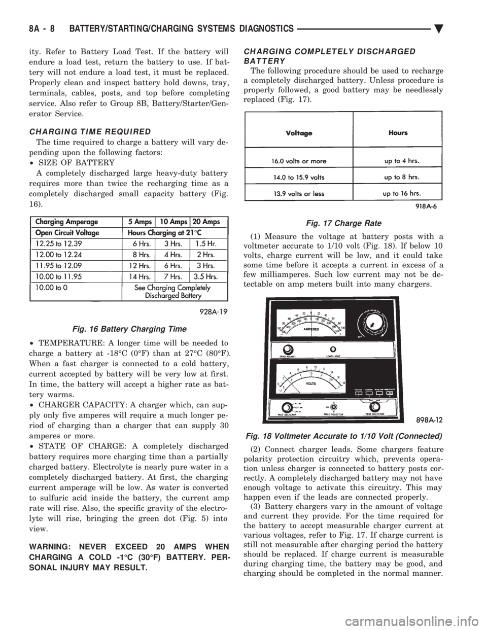
The time required to charge a battery will vary de-
pending upon the following factors:
² SIZE OF BATTERY
A completely discharged large heavy-duty battery
requires more than twice the recharging time as a
completely discharged small capacity battery (Fig.
16).
² TEMPERATURE: A longer time will be needed to
charge a battery at -18ÉC (0ÉF) than at 27ÉC (80ÉF).
When a fast charger is connected to a cold battery,
current accepted by battery will be very low at first.
In time, the battery will accept a higher rate as bat-
tery warms.
² CHARGER CAPACITY: A charger which, can sup-
ply only five amperes will require a much longer pe-
riod of charging than a charger that can supply 30
amperes or more.
² STATE OF CHARGE: A completely discharged
battery requires more charging time than a partially
charged battery. Electrolyte is nearly pure water in a
completely discharged battery. At first, the charging
current amperage will be low. As water is converted
to sulfuric acid inside the battery, the current amp
rate will rise. Also, the specific gravity of the electro-
lyte will rise, bringing the green dot (Fig. 5) into
view.
WARNING: NEVER EXCEED 20 AMPS WHEN
CHARGING A COLD -1ÉC (30ÉF) BATTERY. PER-
SONAL INJURY MAY RESULT.
CHARGING COMPLETELY DISCHARGED BATTERY
The following procedure should be used to recharge
a completely discharged battery. Unless procedure is
properly followed, a good battery may be needlessly
replaced (Fig. 17).
(1) Measure the voltage at battery posts with a
voltmeter accurate to 1/10 volt (Fig. 18). If below 10
volts, charge current will be low, and it could take
some time before it accepts a current in excess of a
few milliamperes. Such low current may not be de-
tectable on amp meters built into many chargers.
(2) Connect charger leads. Some chargers feature
polarity protection circuitry which, prevents opera-
tion unless charger is connected to battery posts cor-
rectly. A completely discharged battery may not have
enough voltage to activate this circuitry. This may
happen even if the leads are connected properly. (3) Battery chargers vary in the amount of voltage
and current they provide. For the time required for
the battery to accept measurable charger current at
various voltages, refer to Fig. 17. If charge current is
still not measurable after charging period the battery
should be replaced. If charge current is measurable
during charging time, the battery may be good, and
charging should be completed in the normal manner.
Fig. 16 Battery Charging Time
Fig. 17 Charge Rate
Fig. 18 Voltmeter Accurate to 1/10 Volt (Connected)
8A - 8 BATTERY/STARTING/CHARGING SYSTEMS DIAGNOSTICS Ä
Page 2317 of 2438

VARIABLE DISPLACEMENT COMPRESSORÐMODEL 6C17 INDEX
page page
Clutch Coil Tests ......................... 17
Compressor ............................. 17
Compressor Clutch Inoperative .............. 13
Compressor Clutch/Coil Assembly ............ 19
Compressor Diagnosis ..................... 13
Compressor Front Shaft Seal ............... 20 Compressor High Pressure Cut-Out Switch
..... 21
Compressor High Pressure Relief Valve (HPR) . . 22
Compressor Identification ................... 13
Compressor Main or Sub Control Valves ....... 22
Compressor Noise ........................ 13
General Information ....................... 13
GENERAL INFORMATION
The Variable Displacement Compressor (VDC) pro-
vides maximum A/C performance under most condi-
tions. It is designed to operate continuously without
any cycling of the compressor clutch. The compressor
has a variable angle wobble plate with six axially
oriented cylinders. During vehicle A/C system operation, the compres-
sor will change its displacement to match the vehi-
cles A/C cooling demands. When the A/C system
needs more cooling capacity, the compressor will in-
crease its pumping capacity. This is done by increas-
ing the wobble plate angle to increase the piston
stroke. When the A/C system cooling demand is low,
the compressor will decrease its pumping capacity by
reducing the piston pumping stroke. The low cooling
capacity will prevent evaporator from freezing.
COMPRESSOR IDENTIFICATION
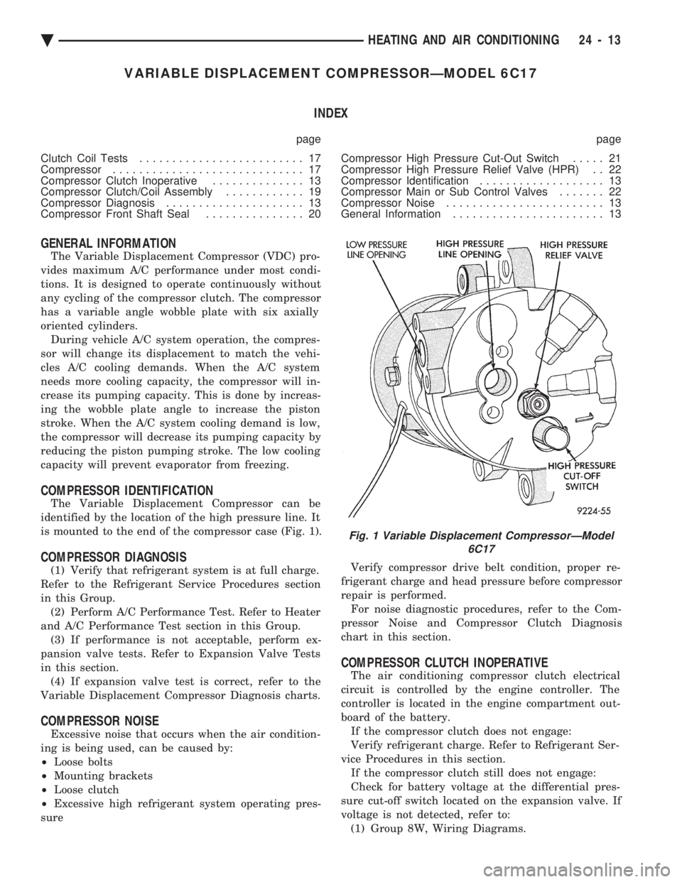
The Variable Displacement Compressor can be
identified by the location of the high pressure line. It
is mounted to the end of the compressor case (Fig. 1).
COMPRESSOR DIAGNOSIS
(1) Verify that refrigerant system is at full charge.
Refer to the Refrigerant Service Procedures section
in this Group. (2) Perform A/C Performance Test. Refer to Heater
and A/C Performance Test section in this Group. (3) If performance is not acceptable, perform ex-
pansion valve tests. Refer to Expansion Valve Tests
in this section. (4) If expansion valve test is correct, refer to the
Variable Displacement Compressor Diagnosis charts.
COMPRESSOR NOISE
Excessive noise that occurs when the air condition-
ing is being used, can be caused by:
² Loose bolts
² Mounting brackets
² Loose clutch
² Excessive high refrigerant system operating pres-
sure Verify compressor drive belt condition, proper re-
frigerant charge and head pressure before compressor
repair is performed. For noise diagnostic procedures, refer to the Com-
pressor Noise and Compressor Clutch Diagnosis
chart in this section.
COMPRESSOR CLUTCH INOPERATIVE
The air conditioning compressor clutch electrical
circuit is controlled by the engine controller. The
controller is located in the engine compartment out-
board of the battery. If the compressor clutch does not engage:
Verify refrigerant charge. Refer to Refrigerant Ser-
vice Procedures in this section. If the compressor clutch still does not engage:
Check for battery voltage at the differential pres-
sure cut-off switch located on the expansion valve. If
voltage is not detected, refer to: (1) Group 8W, Wiring Diagrams.
Fig. 1 Variable Displacement CompressorÐModel 6C17
Ä HEATING AND AIR CONDITIONING 24 - 13