check engine light CHEVROLET VEGA 1976 1.G Owners Manual
[x] Cancel search | Manufacturer: CHEVROLET, Model Year: 1976, Model line: VEGA, Model: CHEVROLET VEGA 1976 1.GPages: 87, PDF Size: 32.36 MB
Page 6 of 87
Downloaded from www.Manualslib.com manuals search engine BEFORE DRIVING YOUR VEGA
DRIVER CHECKLIST
Before Entering Car
1. See that windows , mirrors and
lights are clean.
2. Visually note inflation condition
of tires.
3. Check that area to rear
is clear
if about
to back up.
Before Driving Off
1. Lock all doors.
2. Position seat.
3. Adjust inside and outside
mirrors.
4. Fasten belt restraints.
5. Check that warning bulbs light
when key
is turned to start posi
tion.
6. Release parking brake (and see
that brake warning light turns
off).
7. Be sure you understand your
car and how to operate it safely.
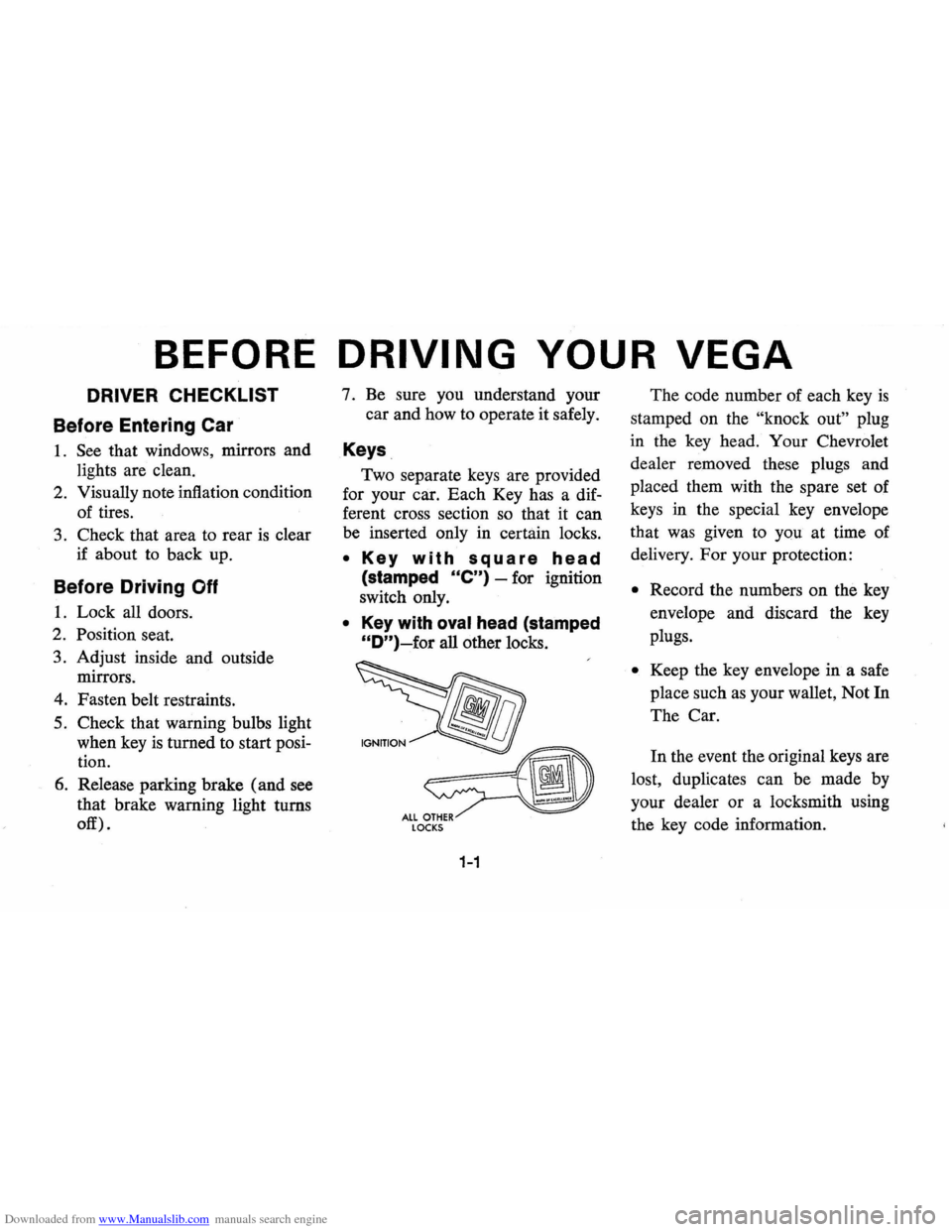
Keys
Two separate keys are provided
for your car. Each Key has a dif
ferent cross section so that it can
be inserted only in certain locks.
• Key with square head
(stamped Ole") -for ignition
switch only.
• Key with oval head (stamped
"D")~for all other locks.
LOCKS
1-1
The code number of each key is
stamped on the "knock out" plug
in the key head. Your Chevrolet
dealer removed these plugs and
placed them with the spare set of
keys in the special key envelope
that was given to you at time of
delivery.
For your protection:
• Record the numbers on the key
envelope and discard the key
plugs.
• Keep the key envelope in a safe
place such
as your wallet, Not In
The Car.
In the event the original keys are
lost, duplicates can be made by
your dealer or a locksmith using
the key code information.
Page 25 of 87
Downloaded from www.Manualslib.com manuals search engine cluster flashes to indicate proper
operation of the front and rear turn
signal lamps.
If the indicator lamp
remains on and does not flash,
check for a defective lamp bulb.
If
the indicator fails to light when the
lever
is moved, check the fuse and
indicator bulb.
NOTE: For operation of hazard
flasher, see page 3-1, in
Section "In
Case of Emergency."
Horn
The horn on your car is actuated
by firmly pressing on the pad in the
center of the steering wheel.
As a good motorist,
~se of the
horn should be kept at a minimum.
However, acquaint yourself
as soon
as possible with this function of
your car, should it ever become
necessary to give a warning to a
pedestrian
or another motorist.
Power Steering
If the steering system power as
sist fails due to some malfunction,
or because the engine has stalled,
the vehicle can still be steered.
However, much greater effort
is re
quired, particularly in sharp turns.
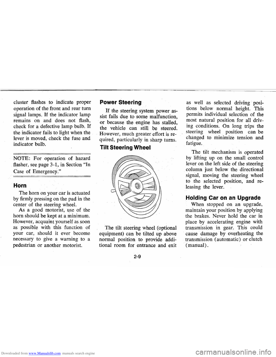
Tilt Steering Wheel
The tilt steering wheel (optional
equipment) can be tilted up above
normal position to provide addi
tional room for entrance and exit
2-9
as well as selected driving· posi
tions below normal height. This
permits individual selection of the
most natural position for
all driv
ing conditions.
On long trips the
steering wheel position can be
changed to minimize tension and
fatigue.
The tilt mechanism
is operated
by lifting up on the small control
lever on the left side of the steering
column just below the directional
signal, moving the steering wheel
to the selected position, and re
leasing the lever.
Holding Car on an Upgrade
When stopped on an upgrade,
maintain your position by applying
the brakes. Never hold the car
in
place by accelerating engine with
transmission in gear. This could
cause damage by overheating
the
. transmission (automatic) or clutch
(manual) .
Page 27 of 87
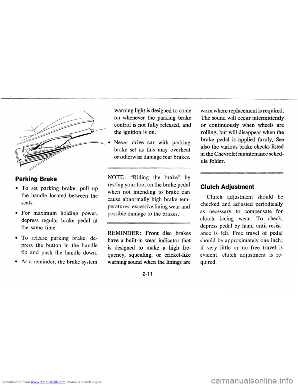
Downloaded from www.Manualslib.com manuals search engine Parking Brake
• To set parking brake, pull up
the handle located between the
seats.
• For maximum holding power,
depress regular brake pedal at
the same time.
• To release parking brake, de
press the button in the handle
tip and push the handle down.
• As a reminder, the brake system warning
light
is designed to come
on whenever the parking brake
control
is not fully released, and
the ignition ·
is on.
• Never drive car with parking
brake set
as this may overheat
or otherwise damage rear brakes.
NOTE: "Riding the brake" by
resting your foot on the brake pedal
when not intending to brake can
cause abnormally high brake tem
peratures, excessive lining wear and
possible damage to the brakes.
REMINDER:
Front disc brakes
have a built-in wear indicator that
is designed to make a high fre
quency, squealing,
or cricket-like
warning sound when the linings are
2-11
worn where replacement is required.
The sound will occur intermittently
or continuously when wheels are
rolling, but will disappear when the
brake pedal
is applied firmly. See
also the various brake checks listed
in the Chevrolet maintenance sched
ule folder.
Clutch Adjustment
Clutch adjustment should be
checked and adjusted periodically
as necessary to compensate for
clutch facing wear.
To check,
depress pedal by hand until resist
ance
is felt. Free travel of pedal
should be approximately one inch;
if very little
or no free travel is
evident , clutch adjustment is re
quired.
Page 31 of 87
Downloaded from www.Manualslib.com manuals search engine Generator Indicator Light
The red light will go on when
the ignition key
is in the "on" posi
tion, but before the engine
is started.
After the engine starts, the light
should go out and remain out.
If
the light remains on when engine
is running, have your Authorized
Chevrolet Dealer locate and correct
the trouble
as soon as possible.
Temp. Pressure Indicator
Light
This indicator light is provided
in the instrument cluster to quickly
warn of an overheated engine
and/or extreme low oil pressure
or oil supply. This light will be on
when the ignition switch is turned
"ON" and should go out after the
engine
is started. Occasionally the
light may be seen to flicker momen
tarily, but this will do no harm. Ex
treme low oil pressure or oil supply
will prevent the electric fuel pump from
operating and under this con
dition the engine will not run.
If the light comes on during ex
treme driving conditions, such
as an
extended idle, turn off the air con
ditioner (if used) and run the en
gine slightly faster than idle speed
with the transmission in
neutral
gear. If the light does not go off
within a short period of time (1-2
minutes), then turn the engine off
until the cause of
the overheating is
corrected. Glance at the instrument
cluster frequently
as you drive to
see if this light is on.
Add Coolant Indicator Light
This indicator light is provided to
warn of a low coolant condition in
the radiator.
If coolant level is low
the yellow
"Add Coolant" warning
light will glow. Coolant level in the
coolant recovery tank, and radiator,
should be checked at the first oppor
tunity.
If necessary add sufficient
2-15
coolant to both the radiator and
coolant recovery tank.
(See Service
and Maintenance, Section 5, for
proper procedure) .
If frequent
additions are required, see your
dealer for a complete cooling sys
tem check.
Brake System Warning
Light
The service brake system is a dual
system designed so that one part will
provide some braking action in the
event of loss of hydraulic pressure
in the other part of the system.
If the
warning light labeled
"Brake" lo
cated in the speedometer face comes
on and stays
on when the ignition is
on and after the brakes have been
firmly applied
it may indicate that
there
is a malfunction in one part of
the brake system.
• As a reminder, the light is de
signed to come
on with the park
ing brake applied and the igni
tion on.
Page 32 of 87
Downloaded from www.Manualslib.com manuals search engine • The light is also designed to come
on during engine starting to
verify that the bulb
is operating
properly.
• Have system repaired if light does
not come
on during check.
• This warning light is not a substi
tute for the visual check of brake
fluid level required
as part of
normal maintenance.
If the light comes on:
• The parking brake control is not
fully released, or,
• The service brake system is par
tially inoperative.
What to do:
1. Check that parking brake is re
leased.
If it is . . .
2.
Pull off the road and stop, care
fully-remembering that:
• Stopping distances may be
greater.
• Greater pedal effort may be re
quired.
• Pedal travel may be greater. 3.
Try out brake operation by start
ing and s,topping on road shoul
der-then:
• If you judge such operation to
be safe, proceed cautiously at
a safe speed to nearest dealer
for repair.
• Or have car towed to dealer for
repair.
Continued operation of the car in this
condition
is dangerous.
Headlight Beam Indicator
Light
The headlights of your car have
high and
low beams to provide you
with proper night-time visibility
for most driving conditions. The
"low" beams are used during most
city driving. The
"high" beams are
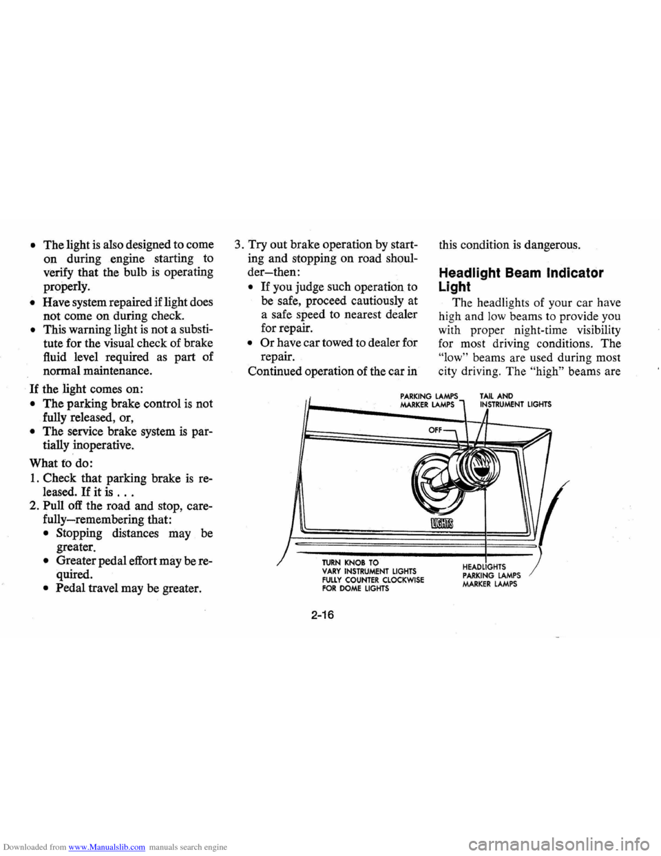
PARKING LAMPS MARKER LAMPS TAIL AND INSTRUMENT LIGHTS
TURN KNOB TO VARY INSTRUMENT LIGHTS FULLY COUNTER CLOCKWISE FOR DOME LIGHTS
2-16
HEADLIGHTS PARKING LAMPS MARKER LAMPS
Page 33 of 87
Downloaded from www.Manualslib.com manuals search engine especially useful when driving on
dark roads since they provide ex
cellent long range illumination. The
headlight beam indicator will be on
whenever the high beams or
"brights" are in use. The Headlight
Beam
Switch controls the headlight
beams (see Page
2-12).
Light Switch
The three position light switch
controls the headlights, taillights,
parking lights, side marker lights,
instrument lights and dome lights
as shown. The headlamp circuit
is protected by a circuit breaker in
the light switch.
An overload on
the breaker will cause the lamps to
"flicker" on and off. If this condi
tion develops, have your headlamp
wiring checked immediately.
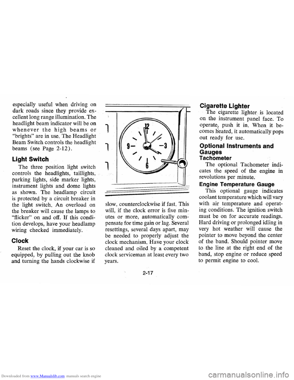
Clock
Reset the clock, if your car is so
equipped, by pulling out the knob
and turning the hands clockwise if
1
1
1
slow, counterclockwise if fast. This
will,
if the clock error is five min
utes
or more, automatically com
pensate for time gain or lag. Several
resettings, several days apart, may
be needed to properly adjust the
clock mechanism. Have your clock
cleaned and oiled by a competent
clock serviceman at least every two
years.
2-17
Cigarette Lighter
The cigarette lighter is located
on the instrument panel
face. To
operate . push it in. When it be
comes
Heated, it automatically pops
out ready for use.
Optional Instruments and
Gauges
Tachometer
The optional Tachometer indi
cates the speed of the engine in
revolutions
per minute.
Engine Temperature Gauge
This optional gauge indicates
coolant temperature which will vary
with air temperature and operat
ing conditions.
The ignition switch
must be on for accurate readings.
Hard driving
or prolonged idling in
very hot weather will cause the
pointer to move beyond the center
of the band. Should pointer move
to the line at the right end of the
band, stop engine or reduce speed
to permit engine to cool.
Page 50 of 87
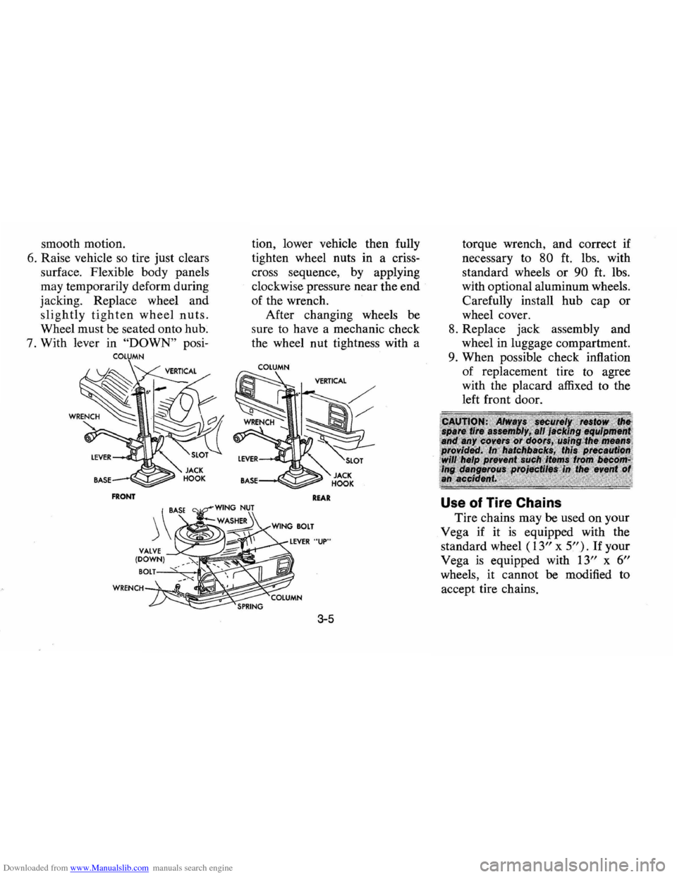
Downloaded from www.Manualslib.com manuals search engine smooth motion.
6. Raise vehicle so tire just clears
surface. Flexible body panels
may temporarily deform during
jacking. Replace wheel and
slightly tighten wheel nuts.
Wheel must be seated onto hub.
7. With lever in
"DOWN" posi
COLUMN
FRONT
tion, lower vehicle then fully
tighten wheel nuts in a criss
cross sequence, by applying
clockwise pressure near the
end
of the wrench.
After changing wheels
be
sure to have a mechanic check
the wheel nut tightness with a
COLUMN
REAR
3-5
torque wrench, and correct if
necessary to
80 ft. lbs. with
standard wheels
or 90 ft. lbs.
with optional aluminum wheels.
Carefully install
hub cap or
wheel cover.
8. Replace jack assembly and
wheel in luggage compartment.
9. When possible check inflation
of replacement tire to agree
with the placard affixed to the
left front door.
Use of Tire Chains
Tire chains may be used on your
Vega if it
is equipped with the
standard wheel
(13" x 5"). If your
Vega
is equipped with 13" x 6"
wheels, it cannot be modified to
accept tire chains.
Page 64 of 87
Downloaded from www.Manualslib.com manuals search engine • If it feels warm, the level should
be close to the
"ADD" mark
( either slightly above
or beloW).
• If it feels hot (cannot be held
comfortably) the level should
be
between the "ADD" and
"FULL" marks.
NOTE: DO NOT OVERFILL. It
takes only one pint to raise level
from
ADD to FULL with a hot
transmission.
Automatic Transmission
Drain
Intervals
The transmission operating tem
perature resulting from the type of
driving conditions under which
your vehicle
is used is the main
consideration in establishing the
proper frequency of transmission
fluid changes.
If you do not use your vehicle
under severe conditions, change the
fluid and filter every
60,000 miles.
Refer to section 6,
"Specifications",
for required fluid quantities.
If the vehicle is usually driven
under one
or more of the follow
ing conditions-considered severe
transmission
service-change the
transmission fluid and filter every
15,000 miles.
• In heavy city traffic.
• Where the outside temperature
regularly reaches
90° F. (32°
C.) for extended periods.
• In very hilly or mountainous
areas.
• Frequent trailer pUlling.
• Commercial uses, such as taxi,
police
car or delivery service.
Manual Transmissions
Lubricant
Level
Every 6 months or 7,500 miles,
whichever occurs first, check lubri
cant level and add lubricant, if nec
essary, to
fill to . level of filler plug
hole.
5-6
• 3-Speed and 4-Speed-Use SAE
80W or SAE 80W-90 GL-5
Gear Lubricant. (For those
vehicles normally operated in
Canada, use
SAE 80W GL5
Gear Lubricant. )
Transmission Shift Linkage
(Manual and Automatic)
Every 7,500 miles or 6 months
lubricate shift linkage and
on
manual transmission floor controls
lever contacting faces with water
resistant
EP chassis lubricant which
meets
GM specification 6031 M.
Clutch Cross -Shaft -Every
30,000 miles or sooner if necessary
-Remove the plug, install a lubri
cation fitting and lubricate with
water resistant
EP Chassis Lubri
cant which meets GM Specification
6031M.
Page 70 of 87
Downloaded from www.Manualslib.com manuals search engine Hood Latche$
Every 6 months or 7,500 miles,
whichever occurs first, lubricate
hood latch assembly and hood
hinge assembly
as follows:
1. Wipe off any accumulation of
dirt or contamination on latch
parts.
2 . Apply Lubriplate or equivalent
to latch pilot bolts and latch
locking plate.
.
3. Apply light engine oil to all pivot
points in release mechanism,
as
well as primary and secondary
latch mechanisms.
4. Lubricate hood hinges.
5. Make hood hinge and latch
mechanism functional check
to
assure the assembly is working
correctly .
Accelerator Linkage
Lubricate with engine oil every
15,000 miles.
Hinges
The following points should be
checked and lubricated every 6
months or
7,500 miles, whichever
occurs first:
hingeS on all doors,
fuel filler door, trunk lid, door lock
striker and door
jamb switches. '
5-12
Air Conditioning
Have your Authorized Dealer
check your Air Conditioning
sys
tem at some time during the winter
months to be sure there has been
no loss in cooling output. During
the summer , see your Authorized
Dealer immediately if you suspect
the system
is not performing as it
should.
NOTE: Your car's air condition
ing system will not operate below
ambient temperature of
300 F
( -1 0 C) , regardless of control
position.
Page 85 of 87
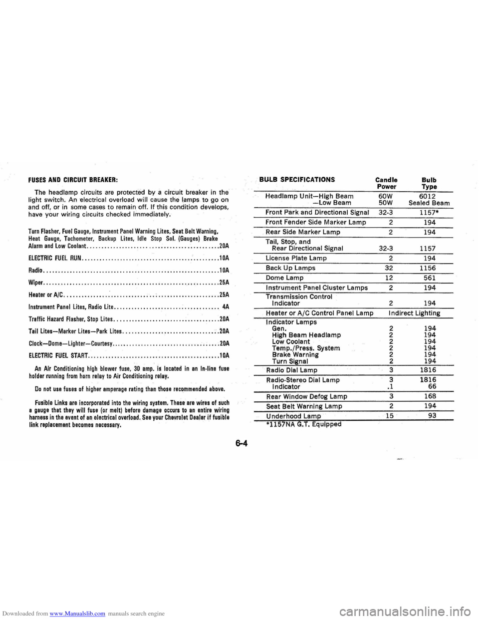
Downloaded from www.Manualslib.com manuals search engine FUSES AND CIRCUIT BREAKER:
The headlamp circuits are protected by a circuit breaker in the
light switch . An -electrical overload will cause the lamps to go on
and off. or in some cases to remain off. If this condition develops,
have your wiring circuits checked immediately.
Turn Flasher, Fuel Gauge,lnstrument Panel Warning Lites, Seat Belt Warning, Heat Gauge. Tachometer. Backup lites, Idle Stop Sol. (Gauges) Brake Alarm and Low Coolant. ............................................ 20A
ELECTRIC FUEL RUN ..................•........................•... 1 OA
Radio ............................................................ 10A
Wiper. ........................................................... 25A
Heater or A/C ............... .-............ ; .. ; ..................... 25A
Instrument Panel Lites, Radio Lite ...........•....... ................. 4A
Traffic Hazard Flasher, Stop Lites ...........•.•................•••... 20A
Tail Lites-Marker lites-Park Lites ...........•.............. .•..... 20A
Clock-Dome-Lighter-Courtesy ..... .......................... ; ..... 20A
ElECTRIC FUEL START ...•................•.•••.•......•.•.••...... 10A
An Air Conditioning high blower fuse, 30 amp. is located in an In-line fuse holder running from horn relay to Air Conditioning relay.
Do not use fuses of higher amperage rating than those recommended above.
Fusible Links are incorporated into the wiring system, These are wires of such a gauge that they will fuse (or melt) before damage occurs to an entire wiring harness in the event of an electrical overload. See your Chevrolet Dealer if fusible link replacement becomes necessary.
BULB SPECIFICATIONS
Headlamp Unit-High Beam -Low Beam
Front Park and Directional
Signal
Front Fender Side Marker Lamp
_ Rear Side Marker Lamp
Tail,
Stop, and
Rear Directional Signal
License Plate Lamp
Back
Up Lamps
Dome Lamp
Instrument Panel Cluster Lamps
Transmission Control
Indicator
Heater
or A/C Control Panel Lamp
I ndicator Lamps
Gen. High Beam Headlamp
Low Coolant
Temp./Press.
System Brake Warning
Turn Signal
Radio Dial Lamp
Radio-Stereo Dial Lamp
Indicator
Rear Window Defog Lamp
Seat Belt Warning Lamp
Underhood Lamp
*1l57NA G.T. Equipped
Candle
Bulb Power Type
60W 6012 SOW Sealed Beam
32-3
1157*
2 194
2 194
32-3 1157
2
194
32 1156
12 561
2
194
2 194
I ndirect Lighting
2
194 2 194 2 194 2 194 2 194 2 194
3 1816
3 1816 .1 66
3 168
2 194
15 93