ECU CHRYSLER 300 2015 2.G Owner's Manual
[x] Cancel search | Manufacturer: CHRYSLER, Model Year: 2015, Model line: 300, Model: CHRYSLER 300 2015 2.GPages: 180, PDF Size: 30.54 MB
Page 123 of 180
UNIVERSAL GARAGE DOOR OPENER
(HomeLink®)
• HomeLink® replaces up to three hand-held transmitters that operate devices such as garage
door openers, motorized gates, lighting or home security systems. The HomeLink® unit is
powered by your vehicles 12 Volt battery.
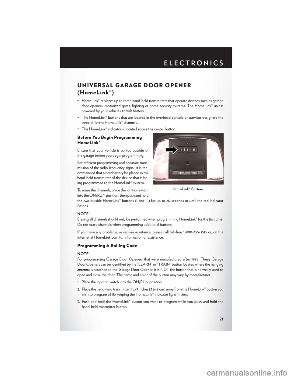
•TheHomeLink®buttonsthatarelocatedintheoverheadconsoleorsunvisordesignatethe
three different HomeLink® channels.
•TheHomeLink®indicatorislocatedabovethecenterbutton.
Before You Begin Programming
HomeLink®
Ensure that your vehicle is parked outside of
the garage before you begin programming.
For efficient programming and accurate trans-
mission of the radio-frequency signal, it is rec-
ommended that a new battery be placed in the
hand-held transmitter of the device that is be-
ing programmed to the HomeLink® system.
To erase the channels, place the ignition switch
into the ON/RUN position, then push and hold
the two outside HomeLink® buttons (I and III) for up to 20 seconds or until the red indicator
flashes.
NOTE:
Erasing all channels should only be performed when programming HomeLink® for the first time.
Do not erase channels when programming additional buttons.
If you have any problems, or require assistance, please call toll-free 1-800-355-3515 or, on the
Internet at HomeLink.com for information or assistance.
Programming A Rolling Code
NOTE:
For programming Garage Door Openers that were manufactured after 1995. These Garage
Door Openers can be identified by the “LEARN” or “TRAIN” button located where the hanging
antenna is attached to the Garage Door Opener. It is NOT the button that is normally used to
open and close the door. The name and color of the button may vary by manufacturer.
1. Place the ignition switch into the ON/RUN position.
2. Place the hand-held transmitter 1 to 3 inches (3 to 8 cm) away from the HomeLink® button you
wish to program while keeping the HomeLink® indicator light in view.
3. Push and hold the HomeLink® button you want to program while you push and hold the
hand-held transmitter button.
HomeLink® Buttons
ELECTRONICS
121
Page 124 of 180
4. Continue to hold both buttons and observe the indicator light. The HomeLink® indicator will
flash slowly and then rapidly after HomeLink® has received the frequency signal from the
hand-held transmitter. Release both buttons after the indicator light changes from slow to
rapid.
5. At the garage door opener motor (in the garage), locate the “LEARN” or “TRAINING”
button. This can usually be found where the hanging antenna wire is attached to the garage
door opener motor. Firmly push and release the “LEARN” or “TRAINING” button.
NOTE:
Yo u h a v e 3 0 s e c o n d s i n w h i c h t o i n i t i a t e t h e n e x t s t e p a f t e r t h e L E A R N b u t t o n h a s b e e n p u s h e d .
6. Return to the vehicle and push the programmed HomeLink® button twice (holding the button
for two seconds each time). If the device is plugged in and activates, programming is
complete.
NOTE:
If the device does not activate, push the button a third time (for two seconds) to complete the
training.
7. To program the remaining two HomeLink® buttons, repeat each step for each remaining
button. DO NOT erase the channels.
Programming A Non-Rolling Code
NOTE:
For programming Garage Door Openers manufactured before 1995.
1. Turn the ignition switch to the ON/RUN position.
2. Place the hand-held transmitter 1 to 3 inches (3 to 8 cm) away from the HomeLink® button you
wish to program while keeping the HomeLink® indicator light in view.
3. Push and hold the HomeLink® button you want to program while you push and hold the
hand-held transmitter button.
4. Continue to hold both buttons and observe the indicator light. The HomeLink® indicator will
flash slowly and then rapidly after HomeLink® has received the frequency signal from the
hand-held transmitter. Release both buttons after the indicator light changes from slow to
rapid.
5. Push and hold the programmed HomeLink® button and observe the indicator light. If the
indicator light stays on constantly, programming is complete and the garage door (or device)
should activate when the HomeLink® button is pushed.
6. To program the two remaining HomeLink® buttons, repeat each step for each remaining
button. DO NOT erase the channels.
Using HomeLink®
To o p e r a t e , p u s h a n d r e l e a s e t h e p r o g r a m m e d H o m e L i n k ® b u t t o n . A c t i v a t i o n w i l l n o w o c c u r f o r
the programmed device (e.g., garage door opener, gate operator, security system, entry door
lock, home/office lighting, etc.). The hand-held transmitter of the device may also be used at any
time.
ELECTRONICS
122
Page 132 of 180
INSTRUMENT CLUSTER INDICATOR LIGHTS
–TurnSignalIndicator
The arrows will flash with the exterior turn signals when the turn signal lever is operated. A tone
will chime, and a DID message will appear if either turn signal is left on for more than 1 mile
(1.6 km).
NOTE:
If either indicator flashes at a rapid rate, check for a defective outside light bulb.
–HighBeamIndicator
Indicates that headlights are on high beam.
–FrontFogLightIndicator
This indicator will illuminate when the front fog lights are on.
–VehicleSecurityLight
This light will flash rapidly for approximately 15 seconds when the vehicle security alarm is arming.
The light will flash at a slower speed continuously after the alarm is set. The security light will also
come on for about three seconds when the ignition is first turned on.
Electronic Speed Control Set
Indicates that the Electronic Speed Control has been set.
-AdaptiveCruiseControl(ACC)ONIndicator
•Ifyourvehicleisequippedwithadaptivecruisecontrol,thecontrolsoperateexactlythesame
as the normal (fixed speed) cruise control with one difference. You can set a specified distance
you would like to maintain between you and the vehicle in front of you.
• If the ACC sensor detects a vehicle ahead, ACC will apply limited braking or acceleration
automatically to maintain a preset following distance, while matching the speed of the vehicle
ahead.
•Ifthesensordoesnotdetectavehicleaheadofyou,ACCwillmaintainafixedsetspeed.
•Referto“SpeedControl”in“OperatingYourVehicle”forfurtherinformationonAdaptive
Cruise Control (ACC) ON operation and proper use.
NOTE:
Adaptive Cruise Control (ACC) increases the driving convenience provided by cruise control
while traveling on highways and major roadways. However, it is not a safety system and not
designed to prevent collisions.
WHAT TO DO IN EMERGENCIES
130
Page 135 of 180

2. Lift the access cover using the pull strap. To hold the cover up and into place, hang the hook
that is located on the end of the strap over the trunk upper weather strip located in the channel
below the rear window.
1—JackBeneathSpareTire2 — Spare Tire3 — Pull Strap
3. Remove the fastener securing the spare tire.
4. Remove the spare tire.
Spare Tire/Tools Location
Spare Tire Fastener
WHAT TO DO IN EMERGENCIES
133
Page 136 of 180
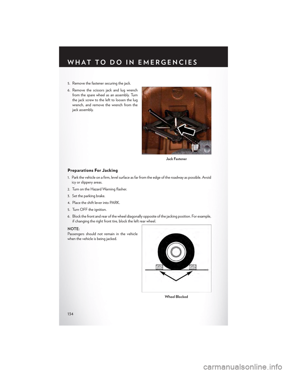
5. Remove the fastener securing the jack.
6. Remove the scissors jack and lug wrench
from the spare wheel as an assembly. Turn
the jack screw to the left to loosen the lug
wrench, and remove the wrench from the
jack assembly.
Preparations For Jacking
1. Park the vehicle on a firm, level surface as far from the edge of the roadway as possible. Avoid
icy or slippery areas.
2. Turn on the Hazard Warning flasher.
3. Set the parking brake.
4. Place the shift lever into PARK.
5. Turn OFF the ignition.
6. Block the front and rear of the wheel diagonally opposite of the jacking position. For example,
if changing the right front tire, block the left rear wheel.
NOTE:
Passengers should not remain in the vehicle
when the vehicle is being jacked.
Jack Fastener
Wheel Blocked
WHAT TO DO IN EMERGENCIES
134
Page 143 of 180

WARNING!
•Whentemperaturesarebelowthefreezingpoint,electrolyteinadischargedbatterymay
freeze. Do not attempt jump-starting because the battery could rupture or explode and
cause personal injury. Battery temperature must be brought above freezing point before
attempting a jump-start.
•Takecaretoavoidtheradiatorcoolingfanwheneverthehoodisraised.Itcanstartanytime
the ignition switch is on. You can be injured by moving fan blades.
•Removeanymetaljewelry,suchaswatchbandsorbracelets,thatmightmakean
inadvertent electrical contact. You could be severely injured.
•Batteriescontainsulfuricacidthatcanburnyourskinoreyesandgeneratehydrogengas
which is flammable and explosive. Keep open flames or sparks away from the battery.
•Donotallowvehiclestotoucheachotherasthiscouldestablishagroundconnectionand
personal injury could result.
• Failure to follow this procedure could result in personal injury or property damage due to
battery explosion.
•Donotconnectthecabletothenegativepost(-)of the discharged battery. The resulting
electrical spark could cause the battery to explode and could result in personal injury.
MANUAL PARK RELEASE
WARNING!
Always secure your vehicle by fully applying the parking brake, before activating the Manual
Park Release. Activating the Manual Park Release will allow your vehicle to roll away if it is not
secured by the parking brake or by proper connection to a tow vehicle. Activating the Manual
Park Release on an unsecured vehicle could lead to serious injury or death for those in or
around the vehicle.
In order to push or tow the vehicle in cases where the transmission will not shift out of PARK (such
as a dead battery), a Manual Park Release is available.
Follow these steps to use the Manual Park Release:
1. Firmly apply the parking brake.
2. Remove the console storage bin to access the Manual Park Release lever.
3. Using a small screwdriver or similar tool, fish the tether strap up through the opening in the
console base.
4. Insert the screwdriver into the slot in the center of the lever, and disengage the lever locking
tab by pushing it to the right.
5. While holding the locking tab in the disengaged position, pull the tether strap to rotate the
lever up and rearward, until it locks in place in the vertical position. The vehicle is now out of
PA R K a n d c a n b e t o w e d . Re l e a s e t h e p a r k i n g b ra ke o n l y w h e n t h e v e h i c l e i s s e c u re l y
connected to a tow vehicle.
WHAT TO DO IN EMERGENCIES
141
Page 144 of 180

To R e s e t T h e M a n u a l P a r k R e l e a s e :
1. Push the latch (at the base of the lever, on the rear side) rearward (away from the lever) to
unlatch the lever.
2. Rotate the Manual Park Release lever forward and down, to its original position, until the
locking tab snaps into place to secure the lever.
3. Pull up gently on the tether strap to confirm that the lever is locked in its stowed position.
4. Tuck the tether strap into the base of the console. Reinstall the console storage bin.
TOWING A DISABLED VEHICLE
This section describes procedures for towing a disabled vehicle using a commercial towing
service.
Towing ConditionWheels OFF TheGroundRWD MODELS AWD MODELS
Flat TowNONE
If transmission is op-erable:• Transmission inNEUTRAL• 30 mph (48 km/h)maxspeed• 30 miles (48 km)maxdistance
NOT ALLOWED
Wheel Lift or DollyTo w
Front
NOT RECOM-MENDED (but, ifused, same limita-tions as above)
NOT ALLOWED
RearNOT RECOM-MENDED
NOT RECOM-MENDED, but, if used:• Ignition in ON/RUN position• Transmission
inNEUTRAL
(NOT in Park)
FlatbedALLBEST METHOD BEST METHOD
Refer to your Owner’s Manual on the DVD for further information.
WHAT TO DO IN EMERGENCIES
142
Page 159 of 180

FUSES
Front Power Distribution Center (Fuses)
The Front Power Distribution Center is located in the engine compartment. This module
contains fuses and relays.
CAUTION!
•Wheninstallingthepowerdistributioncentercover,itisimportanttoensurethecoveris
properly positioned and fully latched. Failure to do so may allow water to get into the
power distribution center and possibly result in an electrical system failure.
• When replacing a blown fuse, it is important to use only a fuse having the correct
amperage rating. The use of a fuse with a rating other than indicated may result in a
dangerous electrical system overload. If a properly rated fuse continues to blow, it
indicates a problem in the circuit that must be corrected.
Cavity Cartridge Fuse Mini-FuseDescription
1––Fuse – Spare
2 40 Amp Green–Radiator Fan #1 – If Equipped
3 50 Amp Red–Power Steering #1 / Radiator Fan(6.2L Supercharged) – If Equipped
4 30 Amp Pink–Starter
5 40 Amp Green–Electronic Stability Control
6 30 Amp Pink–Electronic Stability Control
7––Fuse – Spare
8 20 Amp Blue–Police Ignition Run / ACC # 2
9–20 Amp Yellow All-Wheel Drive Module – If Equipped
10–10 Amp Red Security – If Equipped / Under hoodLamp – Police
11–20 Amp YellowHorns
12–10 Amp RedAir Conditioning Clutch
13––Fuse – Spare
14––Fuse – Spare
15–20 Amp YellowLeft HID – If Equipped
16–20 Amp Yellow Right HID – If Equipped
18 50 Amp Red–Radiator Fan #2 – If Equipped
19 50 Amp Red–Power Steering #2 / Radiator Fan(6.2L Supercharged)
20 30 Amp Pink–Wiper Motor
21 30 Amp Pink– Headlamp Washers – If Equipped / Po-lice Feed
MAINTAINING YOUR VEHICLE
157
Page 170 of 180

WARNING!
Engine exhaust, some of its constituents, and certain vehicle components contain, or emit,
chemicals known to the State of California to cause cancer and birth defects, or other
reproductive harm. In addition, certain fluids contained in vehicles and certain products of
component wear contain, or emit, chemicals known to the State of California to cause cancer
and birth defects, or other reproductive harm.
REPORTING SAFETY DEFECTS IN THE UNITED
STATES
If you believe that your vehicle has a defect that could cause a collision or cause injury or death,
you should immediately inform the National Highway Traffic Safety Administration (NHTSA) in
addition to notifying the manufacturer.
If NHTSA receives similar complaints, it may open an investigation, and if it finds that a safety
defect exists in a group of vehicles, it may order a recall and remedy campaign. However, NHTSA
cannot become involved in individual problems between you, your authorized dealer and the
manufacturer.
To contact NHTSA, you may either call the Auto Safety Hotline toll free at 1-888-327-4236
(TTY: 1-800-424-9153), or go to http://www.safercar.gov; or write to: Administrator, NHTSA,
1200 New Jersey Avenue, SE., West Building, Washington, D.C. 20590. You can also obtain
other information about motor vehicle safety from http://www.safercar.gov.
In Canada
If you believe that your vehicle has a safety defect, you should contact the Customer Service
Department immediately. Canadian customers who wish to report a safety defect to the
Canadian government should contact Transport Canada, Motor Vehicle Defect Investigations
and Recalls at 1-800-333-0510 or go to http://www.tc.gc.ca/roadsafety/.
French Canadian customers who wish to report a safety defect to the Canadian government
should contact Transport Canada, Motor Vehicle Defect Investigations and Recalls at
1-800-333-0510 or go to http://www.tc.gc.ca/securiteroutiere/.
CONSUMER ASSISTANCE
168
Page 173 of 180
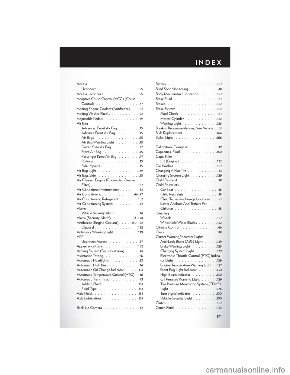
Access
Uconnect...............55
Access, Uconnect.............55
Adaptive Cruise Control (ACC) (Cruise
Control)................37
Adding Engine Coolant (Antifreeze) . . .152
Adding Washer Fluid...........152
Adjustable Pedals.............29Air BagAdvanced Front Air Bag........15Advance Front Air Bag.........15Air Bags . . . . . . . . . . . . . . . .15Air Bag Warning Light.........15Driver Knee Air Bag . . . . . . . . . .17Front Air Bag . . . . . . . . . . . . .15Passenger Knee Air Bag........17Rollover . . . . . . . . . . . . . . . .15Side Impacts..............15Air Bag Light . . . . . . . . . . . . . ..129Air Bag, Side . . . . . . . . . . . . . . . .15Air Cleaner, Engine (Engine Air CleanerFilter).................152Air Conditioner Maintenance.......152Air Conditioning............46, 47Air Conditioning Refrigerant.......152Air Conditioning System.........152AlarmVehicle Security Alarm.........14Alarm (Security Alarm)........14, 130Antifreeze (Engine Coolant).....150, 152Disposal................152Anti-Lock Warning Light.........129APPUconnect Access............57Appearance Care.............152Arming System (Security Alarm)......14Assistance Towing.............126Automatic Headlights...........33Automatic High Beams..........34Automatic Oil Change Indicator.....131Automatic Temperature Control (ATC) . .46Automatic Transmission..........43Adding Fluid.............151Fluid Type..............151Axle Fluid.................151Axle Lubrication..............151
Back-Up Camera . . . . . . . . . . . . .42
Battery..................152
Blind Spot Monitoring...........48
Body Mechanism Lubrication.......152
Brake Fluid................151
Brakes. . . . . . . . . . . . . . . . . ..152
BrakeSystem...............152
Fluid Check..............151
Master Cylinder...........152Warning Light............128Break-In Recommendations, New Vehicle. .31Bulb Replacement............166Bulbs, Light................166
Calibration, Compass...........119Capacities, Fluid.............150Caps, FillerOil (Engine).............152Car Washes................152Changing A Flat Tire...........132Charging System Light..........129Child Restraint...............18Child RestraintsCar Seat................18Child Restraints............18Child Tether Anchorage Locations . . .21Lower Anchors And Tethers ForChildren................18CleaningWheels................152Windshield Wiper Blades.......152Climate Control..............46Clock . . . . . . . . . . . . . . . . . ..118Cluster Warning/Indicator LightsAnti-Lock Brake (ABS) Light.....129Brake Warning Light..........128Charging System Light........129Electronic Throttle Control (ETC) Indica-tor Light...............129Engine Temperature Warning Light . .127Front Fog Light Indicator.......130High Beam Indicator.........130Oil Pressure Warning Light......129Ti re Pre s s u re M o n i t o r i n g S y s t e m ( T P M S )Light.................126Turn Signal Indicator.........130Vehicle Security Light.........130Clutch . . . . . . . . . . . . . . . . ..152Clutch Fluid................152
INDEX
171