CHRYSLER 300 2015 2.G Owner's Guide
Manufacturer: CHRYSLER, Model Year: 2015, Model line: 300, Model: CHRYSLER 300 2015 2.GPages: 180, PDF Size: 30.54 MB
Page 31 of 180
WARNING!
•Whenthe“Hot”symbolisselected,avoidcontactwiththeheatedportionofthecup-
holder in order to avoid burns.
•Personswhoareunabletofeelpaintotheskinbecauseofadvancedage,chronicillness,
diabetes, spinal cord injury, medication, alcohol use, exhaustion or other physical condi-
tions must exercise care when using the heated cup holders. It may cause burns even at low
temperatures, especially if used for long periods of time.
• Keep the cupholders free of debris such as anything that insulates against heat, for this
may cause the cup holders to overheat. Coming in contact with overheated cup holders
could cause serious burns due to the increased surface temperature.
ADJUSTABLE PEDALS
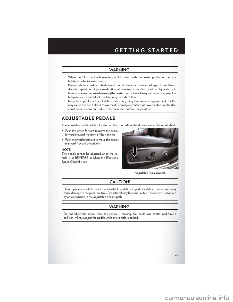
The adjustable pedal switch is located on the front side of the driver’s seat cushion side shield.
•Pushtheswitchforwardtomovethepedals
forward (toward the front of the vehicle).
•Pushtheswitchrearwardtomovethepedals
rearward (toward the driver).
NOTE:
The pedals cannot be adjusted when the ve-
hicle is in REVERSE or when the Electronic
Speed Control is set.
CAUTION!
Do not place any article under the adjustable pedals or impede its ability to move, as it may
cause damage to the pedal controls. Pedal travel may become limited if movement is stopped
by an obstruction in the adjustable pedal's path.
WARNING!
Do not adjust the pedals while the vehicle is moving. You could lose control and have a
collision. Always adjust the pedals while the vehicle is parked.
Adjustable Pedals Switch
GETTING STARTED
29
Page 32 of 180
TILT/TELESCOPING STEERING COLUMN
Manual Tilt/Telescoping Steering Column
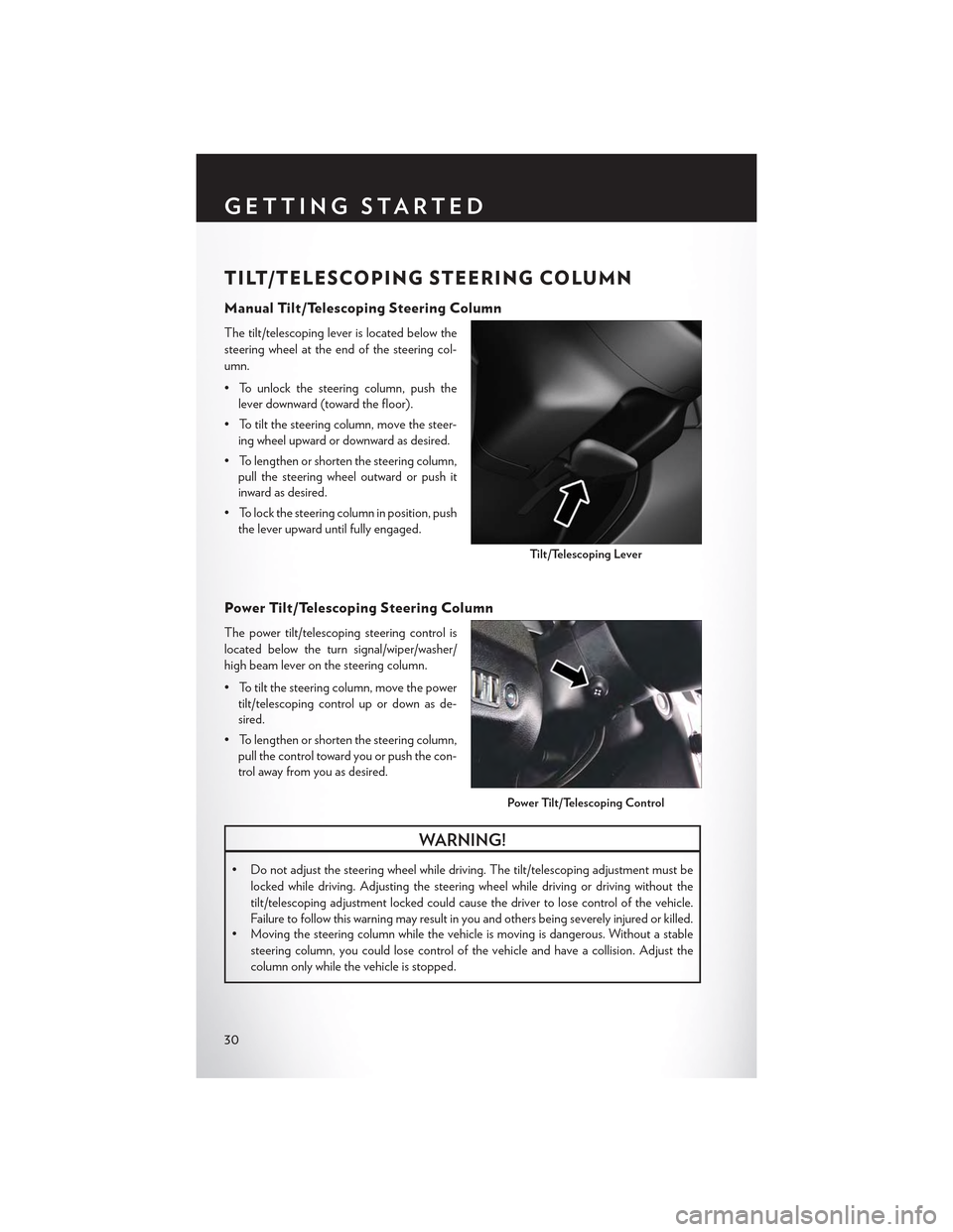
The tilt/telescoping lever is located below the
steering wheel at the end of the steering col-
umn.
• To unlock the steering column, push the
lever downward (toward the floor).
•Totiltthesteeringcolumn,movethesteer-
ing wheel upward or downward as desired.
• To lengthen or shorten the steering column,
pull the steering wheel outward or push it
inward as desired.
• To lock the steering column in position, push
the lever upward until fully engaged.
Power Tilt/Telescoping Steering Column
The power tilt/telescoping steering control is
located below the turn signal/wiper/washer/
high beam lever on the steering column.
•Totiltthesteeringcolumn,movethepower
tilt/telescoping control up or down as de-
sired.
• To lengthen or shorten the steering column,
pull the control toward you or push the con-
trol away from you as desired.
WARNING!
• Do not adjust the steering wheel while driving. The tilt/telescoping adjustment must be
locked while driving. Adjusting the steering wheel while driving or driving without the
tilt/telescoping adjustment locked could cause the driver to lose control of the vehicle.
Failure to follow this warning may result in you and others being severely injured or killed.•Movingthesteeringcolumnwhilethevehicleismovingisdangerous.Withoutastable
steering column, you could lose control of the vehicle and have a collision. Adjust the
column only while the vehicle is stopped.
Ti l t / Te l e s c o p i n g Le v e r
Power Tilt/Telescoping Control
GETTING STARTED
30
Page 33 of 180

ENGINE BREAK-IN RECOMMENDATIONS
Alongbreak-inperiodisnotrequiredfortheengineanddrivetrain(transmissionandaxle)inyour
vehicle.
Drive moderately during the first 300 miles (500 km). After the initial 60 miles (100 km), speeds
up to 50 or 55 mph (80 or 90 km/h) are desirable.
While cruising, brief full-throttle acceleration within the limits of local traffic laws contributes to a good
break-in. Wide-open throttle acceleration in low gear can be detrimental and should be avoided.
The engine oil installed in the engine at the factory is a high-quality energy conserving type
lubricant. Oil changes should be consistent with anticipated climate conditions under which
vehicle operations will occur. Refer to “Maintaining Your Vehicle,” for the recommended viscosity
and quality grades.
NOTE:
A new engine may consume some oil during its first few thousand miles (kilometers) of operation.
This should be considered a normal part of the break-in and not interpreted as an indication of an
engine problem or malfunction.
CAUTION!
Never use Non-Detergent Oil or Straight Mineral Oil in the engine or damage may result.
OPERATING YOUR VEHICLE
31
Page 34 of 180

TURN SIGNAL/WIPER/WASHER/HIGH BEAM
LEVER
Tu r n S i g n a l / L a n e C h a n g e A s s i s t
Ta p t h e l e v e r u p o r d o w n o n c e a n d t h e t u r n s i g n a l ( r i g h t o r l e f t ) w i l l f l a s h t h r e e t i m e s a n d
automatically turn off.
Front Wipers
Intermittent, Low And High Operation
Rotate the end of the lever to the first detent position for one of four intermittent settings, the
second detent for low wiper operation and the third detent for high wiper operation.
Mist
Rotate the end of the lever rearward when a single wipe is desired.
NOTE:
The mist feature does not activate the washer pump; therefore, no washer fluid will be sprayed on
the windshield. The wash function must be activated in order to spray the windshield with washer
fluid.
Washer Operation
Push the end of the lever inward and hold for as long as spray is desired.
Multifunction Lever
1 — Push For Washer2 — Rotate Downward For Mist3—PushLeverForHighBeams
OPERATING YOUR VEHICLE
32
Page 35 of 180

Rain Sensing Wipers
This feature senses moisture on the vehicle's windshield and automatically activates the wipers
for the driver when the switch is in the intermittent position. Rotate the end of the lever to one of
four settings to activate this feature and adjust sensitivity.
Rain Sensing can be turned on and off using the Uconnect® System, refer to the Owner's Manual
on the DVD for further details.
High Beam Operation
Push the lever forward to activate the high beams. Pull the lever toward you for flash to pass.
NOTE:
For safe driving, turn off the high beams when oncoming traffic is present to prevent headlight
glare and as a courtesy to other motorists.
HEADLIGHT SWITCH
Automatic Headlights/Parking Lights/Headlights
• Rotate the headlight switch, located on the
instrument panel to the left of the steering
wheel, to the first detent from the off posi-
tion for parking lightand to the sec-
ond detent for headlight.
•Withtheparkinglightsorlowbeamhead-
lights on, push the headlight switch for fog
lights. Pushing the switch a second time will
deactivate the front fog lights. Turning the
headlight switch off will also deactivate the
fog lights.
• Rotate the headlight switch to “AUTO” for
AUTO headlights.
•WhensettoAUTO,thesystemautomati-
cally turns the headlights on or off based on
ambient light levels.
Light Control Switches
1 — Auto2 — Push For Fog Lights3 — Rotate Headlight Switch4 — Rotate Dimmer5 — Rotate Ambient Light Control
OPERATING YOUR VEHICLE
33
Page 36 of 180
Automatic High Beams
The Automatic High Beams system provides increased forward lighting at night by automating
high beam control through the use of a digital camera mounted above the inside rearview mirror.
This camera detects vehicle specific light and automatically switches from high beams to low
beams until the approaching vehicle is out of view. This feature is programmable through the
Uconnect® system. Refer to “Uconnect® Settings” in “Understanding Your Instrument Panel” in
the Owner's Manual on the DVD for further details.
Instrument Panel Dimmer
•Rotatethedimmercontroltotheextremebottompositiontofullydimtheinstrumentpanel
lights and prevent the interior lights from illuminating when a door is opened.
•Rotatethedimmercontroluptoincreasethebrightnessoftheinstrumentpaneland
cupholders when the parking lights or headlights are on.
• Rotate the dimmer control up to the next detent position to fully brighten the odometer and
radio when the parking lights or headlights are on.
• Rotate the dimmer control up to the last detent position to turn on the interior lighting.
•Ifyourvehicleisequippedwithatouchscreen,thedimmingisprogrammablethroughthe
Uconnect® system. Refer to “Uconnect® Settings” in “Understanding Your Instrument Panel”
in the Owner's Manual on the DVD for further details.
Ambient Light Dimmer
• Rotate the ambient light control up or down to increase or decrease the brightness of the
release handle, map pocket (if equipped), overhead and floor lighting when the parking lights
or headlights are on.
• Rotate to extreme bottom position to turn off.
OPERATING YOUR VEHICLE
34
Page 37 of 180
ELECTRONIC SPEED CONTROL
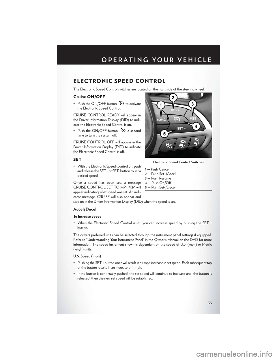
The Electronic Speed Control switches are located on the right side of the steering wheel.
Cruise ON/OFF
• Push the ON/OFF buttonto activate
the Electronic Speed Control.
CRUISE CONTROL READY will appear in
the Driver Information Display (DID) to indi-
cate the Electronic Speed Control is on.
• Push the ON/OFF buttona second
time to turn the system off.
CRUISE CONTROL OFF will appear in the
Driver Information Display (DID) to indicate
the Electronic Speed Control is off.
SET
• With the Electronic Speed Control on, push
and release the SET+ or SET- button to set a
desired speed.
Once a speed has been set, a message
CRUISE CONTROL SET TO MPH/KM will
appear indicating what speed was set. An indi-
cator message, CRUISE will also appear and
stay on in the Driver Information Display (DID) when the speed is set.
Accel/Decel
To Increase Speed
•WhentheElectronicSpeedControlisset,youcanincreasespeedbypushingtheSET+
button.
The drivers preferred units can be selected through the instrument panel settings if equipped.
Refer to “Understanding Your Instrument Panel” in the Owner’s Manual on the DVD for more
information. The speed increment shown is dependant on the speed of U.S. (mph) or Metric
(km/h) units:
U.S. Speed (mph)
• Pushing the SET+button once will result in a 1 mph increase in set speed. Each subsequent tap
of the button results in an increase of 1 mph.
• If the button is continually pushed, the set speed will continue to increase until the button is
released, then the new set speed will be established.
Electronic Speed Control Switches
1 — Push Cancel2—PushSet+/Accel3 — Push Resume4 — Push On/Off5 — Push Set-/Decel
OPERATING YOUR VEHICLE
35
Page 38 of 180

Metric Speed (km/h)
• Pushing the SET+button once will result in a 1 km/h increase in set speed. Each subsequent
tap of the button results in an increase of 1 km/h.
• If the button is continually pushed, the set speed will continue to increase until the button is
released, then the new set speed will be established.
To Decrease Speed
•WhentheElectronicSpeedControlisset,youcandecreasespeedbypushingtheSET-
button.
The drivers preferred units can be selected through the instrument panel settings if equipped.
Refer to “Understanding Your Instrument Panel” in the Owner’s Manual on the DVD for more
information. The speed decrement shown is dependant on the speed of U.S. (mph) or Metric
(km/h) units:
U.S. Speed (mph)
• Pushing the SET-button once will result in a 1 mph decrease in set speed. Each subsequent
tap of the button results in a decrease of 1 mph.
• If the button is continually pushed, the set speed will continue to decrease until the button is
released, then the new set speed will be established.
Metric Speed (km/h)
• Pushing the SET-button once will result in a 1 km/h decrease in set speed. Each subsequent
tap of the button results in a decrease of 1 km/h.
• If the button is continually pushed, the set speed will continue to decrease until the button is
released, then the new set speed will be established.
Resume
• To resume a previously selected set speed in memory, push the RES button and release.
Cancel
• Push the CANCEL button, or apply the brakes to cancel the set speed and maintain the set
speed memory.
•PushtheON/OFFbuttontoturnthesystemoffanderasethesetspeedmemory.
WARNING!
Leaving the Electronic Speed Control system on when not in use is dangerous. You could
accidentally set the system or cause it to go faster than you want. You could lose control and
have an accident. Always leave the system OFF when you are not using it.
OPERATING YOUR VEHICLE
36
Page 39 of 180
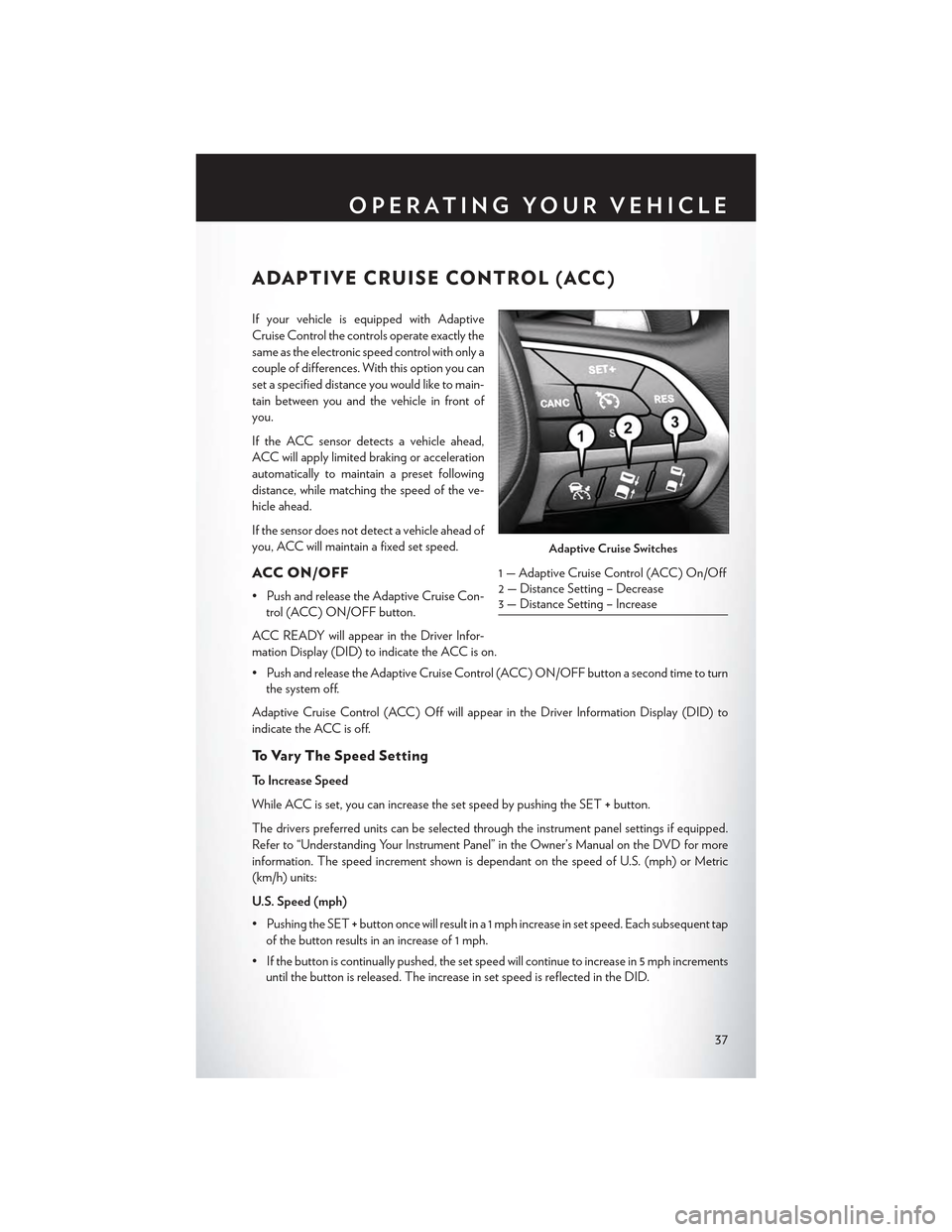
ADAPTIVE CRUISE CONTROL (ACC)
If your vehicle is equipped with Adaptive
Cruise Control the controls operate exactly the
same as the electronic speed control with only a
couple of differences. With this option you can
set a specified distance you would like to main-
tain between you and the vehicle in front of
you.
If the ACC sensor detects a vehicle ahead,
ACC will apply limited braking or acceleration
automatically to maintain a preset following
distance, while matching the speed of the ve-
hicle ahead.
If the sensor does not detect a vehicle ahead of
you, ACC will maintain a fixed set speed.
ACC ON/OFF
•PushandreleasetheAdaptiveCruiseCon-
trol (ACC) ON/OFF button.
ACC READY will appear in the Driver Infor-
mation Display (DID) to indicate the ACC is on.
•PushandreleasetheAdaptiveCruiseControl(ACC)ON/OFFbuttonasecondtimetoturn
the system off.
Adaptive Cruise Control (ACC) Off will appear in the Driver Information Display (DID) to
indicate the ACC is off.
To V a r y T h e S p e e d S e t t i n g
To Increase Speed
While ACC is set, you can increase the set speed by pushing the SET+button.
The drivers preferred units can be selected through the instrument panel settings if equipped.
Refer to “Understanding Your Instrument Panel” in the Owner’s Manual on the DVD for more
information. The speed increment shown is dependant on the speed of U.S. (mph) or Metric
(km/h) units:
U.S. Speed (mph)
• Pushing the SET+button once will result in a 1 mph increase in set speed. Each subsequent tap
of the button results in an increase of 1 mph.
• If the button is continually pushed, the set speed will continue to increase in 5 mph increments
until the button is released. The increase in set speed is reflected in the DID.
Adaptive Cruise Switches
1—AdaptiveCruiseControl(ACC)On/Off2 — Distance Setting – Decrease3 — Distance Setting – Increase
OPERATING YOUR VEHICLE
37
Page 40 of 180

Metric Speed (km/h)
• Pushing the SET+button once will result in a 1 km/h increase in set speed. Each subsequent
tap of the button results in an increase of 1 km/h.
• If the button is continually pushed, the set speed will continue to increase in 10 km/h
increments until the button is released. The increase in set speed is reflected in the DID.
To Decrease Speed
While ACC is set, the set speed can be decreased by pushing the SET-button.
The drivers preferred units can be selected through the instrument panel settings if equipped.
Refer to “Understanding Your Instrument Panel” in the Owner’s Manual on the DVD for more
information. The speed increment shown is dependant on the speed of U.S. (mph) or Metric
(km/h) units:
U.S. Speed (mph)
• Pushing the SET-button once will result in a 1 mph decrease in set speed. Each subsequent
tap of the button results in a decrease of 1 mph.
• If the button is continually pushed, the set speed will continue to decrease in 5 mph
decrements until the button is released. The decrease in set speed is reflected in the DID.
Metric Speed (km/h)
• Pushing the SET-button once will result in a 1 km/h decrease in set speed. Each subsequent
tap of the button results in a decrease of 1 km/h.
• If the button is continually pushed, the set speed will continue to decrease in 10 km/h
decrements until the button is released. The decrease in set speed is reflected in the DID.
NOTE:
•WhenyouoverrideandpushtheSET+button or SET-buttons, the new Set Speed will be the
current speed of the vehicle.
•WhenyouusetheSET-button to decelerate, if the engine’s braking power does not slow the
vehicle sufficiently to reach the set speed, the brake system will automatically slow the vehicle.
•TheACCsystemdeceleratesthevehicletoafullstopwhenfollowingatargetvehicle.Ifan
ACC host vehicle follows a target vehicle to a standstill, after two seconds the driver will either
have to push the RES (resume) button, or apply the accelerator pedal to reengage the ACC
to the existing Set Speed.
•TheACCsystemmaintainssetspeedwhendrivinguphillanddownhill.However,aslight
speed change on moderate hills is normal. In addition, downshifting may occur while climbing
uphill or descending downhill. This is normal operation and necessary to maintain set speed.
When driving up hill and down hill, the ACC system will cancel if the braking temperature
exceeds normal range (overheated).
OPERATING YOUR VEHICLE
38