stop start CHRYSLER ASPEN 2008 2.G User Guide
[x] Cancel search | Manufacturer: CHRYSLER, Model Year: 2008, Model line: ASPEN, Model: CHRYSLER ASPEN 2008 2.GPages: 479, PDF Size: 4.3 MB
Page 69 of 479
²When your child restraint is not in use, secure it in the
vehicle with the seat belt or remove it from the vehicle.
Do not leave it loose in the vehicle. In a sudden stop or
collision, it could strike the occupants or seatbacks and
cause serious personal injury.
LATCH - Child Seat Anchorage System (Lower
Anchors and Tether for CHildren)
Your vehicle's second row seat is equipped with the child
restraint anchorage system called LATCH. The LATCH
system provides for the installation of the child restraint
without using the vehicle's seat belts, instead securing
the child restraint using lower anchorages and upper
tether straps from the child restraint to the vehicle
structure. LATCH-compatible child restraint systems are
now available. However, because the lower anchorages
are to be introduced over a period of years, child restraint
systems having attachments for those anchorages will
continue to also have features for installation using the
vehicle's seat belts. Child restraints having tether strapsand hooks for connection to the top tether anchorages
have been available for some time. For some older child
restraints, many child restraint manufacturers offer
add-on tether strap kits or retro-fit kits. You are urged to
take advantage of all the available attachments provided
with your child restraint in any vehicle.
All three second row seating positions have lower an-
chorages that are capable of accommodating LATCH-
compatible child seats having flexible, webbing-mounted
lower attachments. Child seats with fixed lower attach-
ments must be installed in the outboard positions only.
Regardless of the specific type of lower attachment,
NEVERinstall LATCH-compatible child seats such that
two seats share a common lower anchorage. If you are
installing LATCH-compatible child restraints in adjacent
rear seating positions, you can use the LATCH anchors or
the vehicle's seat belt for the outboard position, but you
must use the vehicle's seat belt at the center position. If
your child restraints are not LATCH-compatible, you can
68 THINGS TO KNOW BEFORE STARTING YOUR VEHICLE
Page 204 of 479
INSTRUMENT CLUSTER DESCRIPTION
1. Fuel Gage
The fuel gage shows level of fuel in the tank when
ignition switch is in the ON position.
2. Temperature Gage
The temperature gage indicates engine coolant
temperature. Any reading within the normal
range indicates that the cooling system is operat-
ing satisfactorily. The gage needle in V6 and V8 engines
will likely indicate a high temperature when driving in
hot weather, up mountain grades, in heavy traffic, or
when towing a trailer. If the needle rises to the ªHº mark,
stop the vehicle, shift into NEUTRAL and increase engine
speed for two to three minutes. If the temperature
reading does not return to normal, see your authorized
dealer for service immediately..
CAUTION!
Do not leave your vehicle unattended with the en-
gine running as you would not be able to react to the
temperature indicator if the engine overheats.
The gage pointer will remain near its last reading when
the engine is turned off. It will return to a true reading
when the engine is restarted.
3. Turn Signal Indicators
When a turn signal is activated, a right-pointing or
left-pointing arrow lights up and flashes to indicate the
direction of the turn. These indicators also indicate
proper operation of the front and rear turn signal lights.
If either indicator flashes at a faster rate than normal,
check for a defective bulb. If either indicator fails to light
up when the lever is moved, check for a defective fuse or
turn signal LED. A single chime is activated when the
INSTRUMENT PANEL AND CONTROLS 203
4
Page 210 of 479
ESP/TCS indicator light starts to flash as soon as the tires
lose traction and the ESP system becomes active. The
ESP/TCS indicator light also flashes when TCS is active.
If the ESP/TCS indicator light begins to flash during
acceleration, ease up on the accelerator and apply as little
throttle as possible. Be sure to adapt your speed and
driving to the prevailing road conditions. The ESP/TCS
indicator light becomes illuminated when the ESP-OFF
button has been pressed or ESP is only partially available,
caused by lack of engine management or brake thermal
model.
19. Transmission Temperature Indicator
This light indicates that there is excessive trans-
mission fluid temperature that might occur
with severe usage, such as trailer towing. If this
light comes on, stop the vehicle and run the
engine at idle or faster, with the transmission in NEU-
TRAL until the light goes off.20. Electronic Throttle Control (ETC)
This light informs you of a problem with the
Electronic Throttle Control system. If a prob-
lem is detected, the light will come on while the
engine is running. If the light remains lit with
the engine running your vehicle will usually be drivable,
however, see your authorized dealer for service as soon
as possible. If the light is flashing when the engine is
running, immediate service is required and you may
experience reduced performance, an elevated/rough idle
or engine stall and your vehicle may require towing. The
light will come on when the ignition is first turned on
and remain on for 15 seconds as a bulb check. If the light
does not come on during starting, have the system
checked by your authorized dealer.
21. BRAKE System Warning Light
The red ªBRAKEº warning light will come on when the
ignition key is first turned on, and stay on briefly as a
bulb check. If the bulb does not come on during starting,
INSTRUMENT PANEL AND CONTROLS 209
4
Page 213 of 479
by the vehicle manufacturer on the vehicle placard or tire
inflation pressure label. (If your vehicle has tires of a
different size than the size indicated on the vehicle
placard or tire inflation pressure label, you should deter-
mine the proper tire inflation pressure for those tires.)
As an added safety feature, your vehicle has been
equipped with a Tire Pressure Monitoring System
(TPMS) that illuminates a low tire pressure telltale when
one or more of your tires is significantly under-inflated.
Accordingly, when the low tire pressure telltale illumi-
nates, you should stop and check your tires as soon as
possible, and inflate them to the proper pressure. Driving
on a significantly under-inflated tire causes the tire to
overheat and can lead to tire failure. Under-inflation also
reduces fuel efficiency and tire tread life, and may affect
the vehicle's handling and stopping ability.
Please note that the TPMS is not a substitute for proper
tire maintenance, and it is the driver 's responsibility tomaintain correct tire pressure, even if under-inflation has
not reached the level to trigger illumination of the TPMS
low tire pressure telltale.
Your vehicle has also been equipped with a TPMS
malfunction indicator to indicate when the system is not
operating properly. The TPMS malfunction indicator is
combined with the low tire pressure telltale. When the
system detects a malfunction, the telltale will flash for
approximately one minute and then remain continuously
illuminated. This sequence will continue upon subse-
quent vehicle start-ups as long as the malfunction exists.
When the malfunction indicator is illuminated, the sys-
tem may not be able to detect or signal low tire pressure
as intended. TPMS malfunctions may occur for a variety
of reasons, including the installation of replacement or
alternate tires or wheels on the vehicle that prevent the
TPMS from functioning properly. Always check the
TPMS malfunction telltale after replacing one or more
212 INSTRUMENT PANEL AND CONTROLS
Page 245 of 479

SCAN Button
Pressing the SCAN button will play the first five seconds
of each track in the current list and then forward to the
next song. To stop the SCAN mode and start playing the
desired track, press the SCAN button again.
During the SCAN mode, you can also press the SEEK
button to the left or right to go to the previous or next
tracks.
RND (Random) Button (RES Radios Only)
Pressing the RND button will switch between the shuffle
on and shuffle off modes of the iPodt. If the RND icon is
showing on the radio display then the shuffle mode is on.
List or Browse Mode
During Play mode, pressing any of the following buttons
will take you to List mode. List mode enables you to
scroll through the list of menus and tracks on the iPodt
device.TUNE/SCROLL Knob
In the List mode, the TUNE/SCROLL knob functions in
a similar manner as the scroll wheel on the iPodt.
Turning the TUNE/SCROLL knob clockwise (forward)
and counterclockwise (backward) scrolls through lists,
displaying the track detail on the radio display. Once you
have the track to be played highlighted on the radio
display, press the TUNE/SCROLL knob to select and
start playing the track. By turning the TUNE/SCROLL
knob fast, you can jump through the list faster. During
fast scroll, you may notice a slight delay in updating the
information on the radio display.
During all List modes, the iPodtwill display all lists in
ªwrap-aroundº mode. So if the track you wish to select is
at the bottom of the list, you just turn the TUNE/
SCROLL knob backward (counterclockwise) to get to the
track faster.
244 INSTRUMENT PANEL AND CONTROLS
Page 277 of 479
WARNING!
It is dangerous to shift the gear shift lever out of
PARK or NEUTRAL if the engine speed is higher
than idle speed. If your foot is not firmly on the
brake pedal, the vehicle could accelerate quickly
forward or in reverse. You could lose control of the
vehicle and hit someone or something. Only shift
into gear when the engine is idling normally and
when your right foot is firmly on the brake pedal.
ªRº REVERSE
Use this range only after the vehicle has come to a
complete stop.ªNº NEUTRAL
Shift to NEUTRAL when the vehicle is standing for
prolonged periods with the engine running. The engine
may be started in this range. Set the parking brake if you
must leave the vehicle.
NOTE:Towing the vehicle (except as specified under
Towing A Disabled Vehicle), coasting, or otherwise driv-
ing the vehicle while in NEUTRAL can cause severe
transmission damage
ªDº DRIVE
For most city and highway driving.
ª2º 2nd
For driving slowly in heavy city traffic or on mountain
roads where more precise speed control is desirable. Use
it also when climbing long grades, and for engine brak-
ing when descending moderately steep grades. To pre-
vent excessive engine speed, do not exceed 45 mph (72
km/h) in this range.
276 STARTING AND OPERATING
Page 281 of 479
FOUR-WHEEL DRIVE OPERATION
NV 140 Transfer Case Operating
Information/Precautions ± If Equipped
The NV 140 is a single speed (4 HI range only) transfer
case which provides convenient full-time 4-wheel drive.
No driver interaction is required. This transfer case
divides engine torque almost evenly with 48 percent of
engine torque to the front axle and 52 percent of engine
torque to the rear axle.
Proper operation of 4-wheel drive vehicles depends on
tires of equal size, type and circumference on each wheel.
Any difference in tire size can cause damage to the
transfer case.
Because 4-wheel drive provides improved traction, there
is a tendency to exceed safe turning and stopping speeds.
Do not go faster than road conditions permit.4WD
Normal 4-Wheel Drive High Range - Employs inter-axle
differential. Allows front and rear wheels to rotate at
different speeds. All road surfaces.
NV 244 Generation II Transfer Case Operating
Information / Precautions
The NV 244 Generation II is an electric-shift transfer case
and is operated by the 4WD Control Switch, which is
located on the instrument panel.
The NV 244 Generation II transfer case provides four
mode positions - Normal 4-wheel drive (4WD) high
range, 4-wheel-drive lock (4WD LOCK), 4-wheel drive
low (4WD LOW) range, and NEUTRAL.
This transfer case is equipped with an inter-axle differ-
ential that allows driving the vehicle in the normal
all-wheel drive position (4WD) at all times on any given
road surface, including dry, hard-surfaced roads. The
4WD mode allows the front and rear wheels to rotate at
280 STARTING AND OPERATING
Page 283 of 479
WARNING!
Always engage the parking brake when powering
down the vehicle if the(SVC 4WD(light is illumi-
nated. Not engaging the parking brake may allow the
vehicle to roll, which may cause personal injury.
NOTE:Do not attempt to make a shift while only the
front or rear wheels are spinning. The NV 244 Generation
II transfer case is not equipped with a synchronizer and
therefore the front and rear driveshaft speeds must be
equal for the shift to take place. Shifting while only the
front or rear wheels are spinning can cause damage to the
transfer case.When operating your vehicle in 4WD LOW, the engine
speed is approximately three times that of the 4WD or
4WD LOCK positions at a given road speed. Take care
not to overspeed the engine and do not exceed 25 mph
(40 km/h).
Proper operation of 4-wheel drive vehicles depends on
tires of equal size, type and circumference on each wheel.
Any difference in tire size can cause damage to the
transfer case.
Because 4-wheel drive provides improved traction, there
is a tendency to exceed safe turning and stopping speeds.
Do not go faster than road conditions permit.
282 STARTING AND OPERATING
Page 285 of 479
4WD LOW
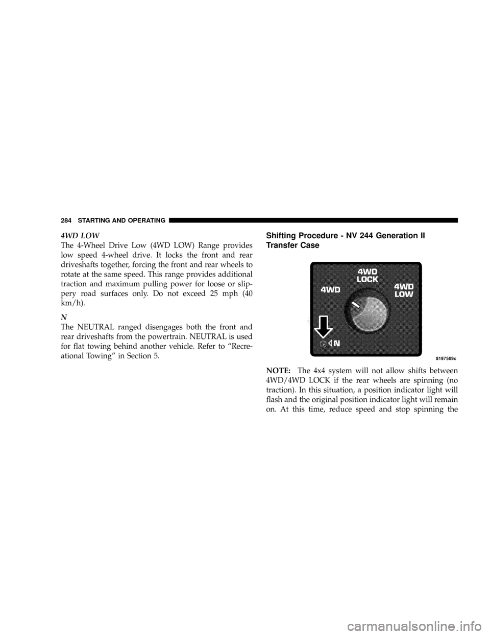
The 4-Wheel Drive Low (4WD LOW) Range provides
low speed 4-wheel drive. It locks the front and rear
driveshafts together, forcing the front and rear wheels to
rotate at the same speed. This range provides additional
traction and maximum pulling power for loose or slip-
pery road surfaces only. Do not exceed 25 mph (40
km/h).
N
The NEUTRAL ranged disengages both the front and
rear driveshafts from the powertrain. NEUTRAL is used
for flat towing behind another vehicle. Refer to ªRecre-
ational Towingº in Section 5.Shifting Procedure - NV 244 Generation II
Transfer Case
NOTE:The 4x4 system will not allow shifts between
4WD/4WD LOCK if the rear wheels are spinning (no
traction). In this situation, a position indicator light will
flash and the original position indicator light will remain
on. At this time, reduce speed and stop spinning the
284 STARTING AND OPERATING
Page 286 of 479

wheels to complete the shift. There may be a delay up to
13 seconds for the shift to complete after the wheels have
stopped spinning.
NOTE:Delayed shifting out of the 4WD LOCK position
may be experienced due to uneven tire wear, low tire
pressure, or excessive loading.
NOTE:When shifting into, or out of 4WD LOW, some
gear noise may be heard. This noise is normal and is not
detrimental to the vehicle or occupants.
Shifting can be performed with the vehicle rolling 2 to 3
mph (3 to 5 km/h) or completely stopped. USE EITHER
OF THE FOLLOWING PROCEDURES:
Preferred Procedure
1. With the engine running, slow the vehicle to 2 to 3
mph (3 to 5 km/h).
2. Shift the transmission into NEUTRAL.3. While still rolling, rotate the transfer case control
switch to the desired position.
4. After the position indicator light has stopped flashing,
shift the transmission back into gear.
Alternate Procedure
1. Bring the vehicle to a complete stop.
2. With the key ON and the engine either OFF or
running, shift the transmission into NEUTRAL.
3. Rotate the transfer case control switch to the desired
position.
4. After the position indicator light has stopped flashing,
shift the transmission back into gear.
NOTE:The ignition key must be ON for a shift to take
place and for the position indicator lights to be operable.
If the key is not ON then the shift will not take place and
no position indicator lights will be on or flashing.
STARTING AND OPERATING 285
5