stop start CHRYSLER ASPEN 2008 2.G Owner's Guide
[x] Cancel search | Manufacturer: CHRYSLER, Model Year: 2008, Model line: ASPEN, Model: CHRYSLER ASPEN 2008 2.GPages: 479, PDF Size: 4.3 MB
Page 313 of 479
WARNING!
Overloading of your tires is dangerous. Overloading
can cause tire failure, affect vehicle handling, and
increase your stopping distance. Use tires of the
recommended load capacity for your vehicle. Never
overload them.
TIRES Ð GENERAL INFORMATION
Tire Pressure
Proper tire inflation pressure is essential to the safe and
satisfactory operation of your vehicle. Three primary
areas are affected by improper tire pressure:1. SafetyÐ
WARNING!
²Improperly inflated tires are dangerous and can
cause accidents.
²Under-inflation increases tire flexing and can result
in tire failure.
²Over-inflation reduces a tire's ability to cushion
shock. Objects on the road and chuckholes can cause
damage that result in tire failure.
²Unequal tire pressures can cause steering problems.
You could lose control of your vehicle.
²Over-inflated or under-inflated tires can affect ve-
hicle handling and can fail suddenly, resulting in loss
of vehicle control.
²Unequal tire pressures from one side of the vehicle
to the other can cause the vehicle to drift to the right or
left.
²Always drive with each tire inflated to the recom-
mended cold tire inflation pressure.
312 STARTING AND OPERATING
Page 318 of 479

original equipped tire on the front or rear axle of your
vehicle, but it is not. Installation of this limited-use spare
tire affects vehicle handling. Since it is not the same tire,
replace (or repair) the original tire and reinstall on the
vehicle at the first opportunity.
WARNING!
The limited-use spare tires are for emergency use
only. Installation of this limited-use spare tire affects
vehicle handling. With this tire, do not drive more
than 50 mph (80 km/h). Keep inflated to the cold tire
inflation pressure listed on either your tire placard or
limited-use spare tire and wheel assembly. Replace
(or repair) the original tire at the first opportunity
and reinstall it on your vehicle. Failure to do so could
result in loss of vehicle control.
Tire Spinning
When stuck in mud, sand, snow, or ice conditions, do not
spin your vehicle's wheels faster than 30 mph (48 km/h)
or for longer than 30 seconds continuously without
stopping when you are stuck.
For additional information, refer to ªFreeing A Stuck
Vehicleº in Section 6.
WARNING!
Fast spinning tires can be dangerous. Forces gener-
ated by excessive wheel speeds may cause tire dam-
age or failure. A tire could explode and injure some-
one. Do not spin your vehicle's wheels faster than 30
mph (48 km/h) or for more than 30 seconds continu-
ously when you are stuck, and don't let anyone near
a spinning wheel, no matter what the speed.
STARTING AND OPERATING 317
5
Page 322 of 479

Improper alignment will not cause vehicle vibration.
Vibration may be a result of tire and wheel out-of-
balance. Proper balancing will reduce vibration and
avoid tire cupping and spotty wear.
SUPPLEMENTAL TIRE PRESSURE INFORMATION
Ð IF EQUIPPED
A light load vehicle condition is defined as two passen-
gers [150 lbs (68 kg) each] plus 200 lbs (91 kg) of cargo.
Cold tire inflation pressures for a lightly loaded vehicle
will be found on the face of the driver's door.
TIRE CHAINS
Use ªClass Sº chains on your vehicle, or other traction
aids that meet SAE Type ªSº specifications.
NOTE:Chains must be the proper size for the vehicle,
as recommended by the chain manufacturer.
CAUTION!
To avoid damage to your vehicle, tires or chains, observe the
following precautions:
²Because of limited chain clearance between tires and other
suspension components, it is important that only chains in
good condition are used. Broken chains can cause serious
vehicle damage. Stop the vehicle immediately if noise
occurs that could suggest chain breakage. Remove the
damaged parts of the chain before further use.
²Install chains as tightly as possible and then retighten
after driving about 1/2 mile (0.8 km).
²Do not exceed 45 mph (72 km/h).
²Drive cautiously and avoid severe turns and large bumps,
especially with a loaded vehicle.
²Do not install tire chains on front wheels of 4x2 vehicles.
²Do not drive for a prolonged period on dry pavement.
²Observe the tire chain manufacturer's instructions on
method of installation, operating speed, and conditions
for usage. Always use the lower suggested operating
speed of the chain manufacturer if different than the
speed recommended by the manufacturer.
STARTING AND OPERATING 321
5
Page 327 of 479
CAUTION!
After inspecting or adjusting the tire pressure always
reinstall the valve stem cap. This will prevent mois-
ture and dirt from entering the valve stem, which
could damage the tire pressure monitoring sensor.
NOTE:
²The TPMS is not intended to replace normal tire care
and maintenance, or to provide warning of a tire
failure or condition.
²The TPMS should not be used as a tire pressure gauge
while adjusting your tire pressure.
²Driving on a significantly under-inflated tire causes
the tire to overheat and can lead to tire failure.Under-inflation also reduces fuel efficiency and tire
tread life, and may affect the vehicle's handling and
stopping ability.
²The TPMS is not a substitute for proper tire mainte-
nance, and it is the driver 's responsibility to maintain
correct tire pressure using an accurate tire gauge, even
if under-inflation has not reached the level to trigger
illumination of the Tire Pressure Monitoring Telltale
Lamp.
²Seasonal temperature changes will affect tire pressure,
and the TPMS will monitor the actual tire pressure in
the tire.
Base System ± If Equipped
The Tire Pressure Monitor System (TPMS) uses wireless
technology with wheel rim mounted electronic sensors to
monitor tire pressure levels. Sensors, mounted to each
wheel as part of the valve stem, transmit tire pressure
readings to the receiver module.
326 STARTING AND OPERATING
Page 328 of 479
NOTE:It is particularly important for you to check the
tire pressure in all of your tires regularly and to maintain
the proper pressure.
The TPMS consists of the following components:
²Receiver module
²Four tire pressure monitoring sensors
²Tire Pressure Monitoring Telltale Lamp
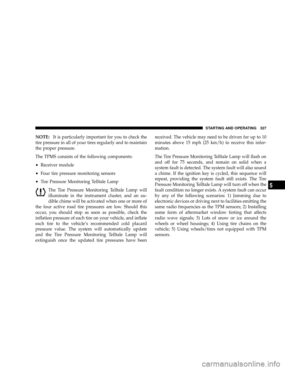
The Tire Pressure Monitoring Telltale Lamp will
illuminate in the instrument cluster, and an au-
dible chime will be activated when one or more of
the four active road tire pressures are low. Should this
occur, you should stop as soon as possible, check the
inflation pressure of each tire on your vehicle, and inflate
each tire to the vehicle's recommended cold placard
pressure value. The system will automatically update
and the Tire Pressure Monitoring Telltale Lamp will
extinguish once the updated tire pressures have beenreceived. The vehicle may need to be driven for up to 10
minutes above 15 mph (25 km/h) to receive this infor-
mation.
The Tire Pressure Monitoring Telltale Lamp will flash on
and off for 75 seconds, and remain on solid when a
system fault is detected. The system fault will also sound
a chime. If the ignition key is cycled, this sequence will
repeat, providing the system fault still exists. The Tire
Pressure Monitoring Telltale Lamp will turn off when the
fault condition no longer exists. A system fault can occur
by any of the following scenarios: 1) Jamming due to
electronic devices or driving next to facilities emitting the
same radio frequencies as the TPM sensors; 2) Installing
some form of aftermarket window tinting that affects
radio wave signals; 3) Lots of snow or ice around the
wheels or wheel housings; 4) Using tire chains on the
vehicle; 5) Using wheels/tires not equipped with TPM
sensors.
STARTING AND OPERATING 327
5
Page 330 of 479
The TPMS consists of the following components:
²Receiver module
²Four tire pressure monitoring sensors
²Three trigger modules (mounted in three of the four
wheel wells).
²Various TPMS messages, which display in the Elec-
tronic Vehicle Information Center (EVIC), and a
graphic displaying tire pressures.
²Yellow Tire Pressure Monitoring Telltale Light.
Tire Pressure Monitoring Low Pressure Warnings
The Tire Pressure Monitoring Telltale Light will illumi-
nate in the instrument cluster, and an audible chime will
be activated when one or more of the four active road tire
pressures are low. In addition, the EVIC will display a
graphic of the pressure value(s) with the low tire(s)
flashing.Should a low tire condition occur on any of the four
active road tire(s), you should stop as soon as possible,
and inflate the low tire(s) that is flashing on the graphic
display to the vehicle's recommended cold placard pres-
sure value. The system will automatically update, the
graphic display of the pressure value(s) will stop flash-
ing, and the Tire Pressure Monitoring Telltale Light will
extinguish once the updated tire pressure(s) have been
received. The vehicle may need to be driven for up to 10
minutes above 15 mph (25 km/h) to receive this infor-
mation.
Check TPMS Message
The Tire Pressure Monitoring Telltale Light will flash on
and off for 75 seconds, and remain on solid when a
system fault is detected. The system fault will also sound
a chime. The EVIC will display a ªCHECK TPM SYS-
TEMº message for three seconds. This text message is
then followed by a graphic display, with ª- - -ª in place of
STARTING AND OPERATING 329
5
Page 336 of 479

NOTE:Intentional tampering with emissions control
systems can result in civil penalties being assessed
against you.Carbon Monoxide Warnings
WARNING!
Carbon monoxide (CO) in exhaust gases is deadly. Follow the
precautions below to prevent carbon monoxide poisoning:
²Do not inhale exhaust gases. They contain carbon monox-
ide, a colorless and odorless gas which can kill. Never run
the engine in a closed area, such as a garage, and never sit
in a parked vehicle with the engine running for an
extended period. If the vehicle is stopped in an open area
with the engine running for more than a short period,
adjust the ventilation system to force fresh, outside air
into the vehicle.
²Guard against carbon monoxide with proper maintenance.
Have the exhaust system inspected every time the vehicle
is raised. Have any abnormal conditions repaired
promptly. Until repaired, drive with all side windows
fully open.
²Keep the liftgate closed when driving your vehicle to
prevent carbon monoxide and other poisonous exhaust
gases from entering the vehicle.
STARTING AND OPERATING 335
5
Page 348 of 479
Frontal Area
The maximum height and maximum width of the front of
a trailer.
TSC (Trailer Sway Control) ± If Equipped
²
Trailer Sway Control ± Electronic
TSC uses sensors in the vehicle to recognize a swaying
trailer and will take the appropriate actions to attempt to
stop the sway. The system will reduce engine power and
apply individual brakes that will counteract the sway of
the trailer. TSC will become active automatically once the
swaying trailer is recognized. No driver action is re-
quired. TSC cannot stop all trailers from swaying. Al-
ways use caution when towing a trailer and follow the
tongue weight recommendations. Even if your vehicle is
equipped with electronic TSC, mechanical sway control
is recommended when appropriate for the size of your
trailer.
²Trailer Sway Control ± Mechanical
The trailer sway control is a telescoping link that can be
installed between the hitch receiver and the trailer tongue
that typically provides adjustable friction associated with
the telescoping motion to dampen any unwanted trailer
swaying motions while traveling.
Weight-Carrying Hitch
A weight-carrying hitch supports the trailer tongue
weight, just as if it were luggage located at a hitch ball or
some other connecting point of the vehicle. These kind of
hitches are the most popular on the market today and
they're commonly used to tow small- and medium-sized
trailers.
Weight-Distributing Hitch
A weight-distributing system works by applying lever-
age through spring (load) bars. They are typically used
for heavier loads, to distribute trailer tongue weight to
the tow vehicle's front axle and the trailer axle(s). When
STARTING AND OPERATING 347
5
Page 356 of 479

þAn electronically actuated trailer brake controller is
required when towing a trailer with electronically
actuated brakes. When towing a trailer equipped with
a hydraulic surge actuated brake system, an electronic
brake controller is not required.
þTrailer brakes are recommended for trailers over 1,000
lbs (454 kg) and required for trailers in excess of 2,000
lbs (907 kg).
CAUTION!
If the trailer weighs more than 1,000 lbs (454 kg)
loaded, it should have its own brakes and they
should be of adequate capacity. Failure to do this
could lead to accelerated brake lining wear, higher
brake pedal effort, and longer stopping distances.
WARNING!
Do not connect trailer brakes to your vehicle's hy-
draulic brake lines. It can overload your brake sys-
tem and cause it to fail. You might not have brakes
when you need them and could have an accident.
Towing any trailer will increase your stopping dis-
tance. When towing you should allow for additional
space between your vehicle and the vehicle in front
of you. Failure to do so could result in an accident.
STARTING AND OPERATING 355
5
Page 357 of 479

Towing Requirements Ð Trailer Lights and Wiring
Whenever you pull a trailer, regardless of the trailer size,
stop lights and turn signals on the trailer are required for
motoring safety.
The Trailer Tow Package may include a 4- and 7-pin
wiring harness. Use a factory approved trailer harness
and connector.
NOTE:Do not cut or splice wiring into the vehicle's
wiring harness.
The electrical connections are all complete to the vehicle
but you must mate the harness to a trailer connector.
Refer to the following illustrations:
4-Pin Connector
356 STARTING AND OPERATING